1
!
!
!
!
!
Design and Implementation of a Low-Cost Mobile Robotic
Platform!
!
João Pedro Hilário Teixeira de Sousa!
!
!
Thesis to obtain the Master of Science Degree in!
Electrical and Computer Engineering!
!
Supervisor: ! Prof. Pedro Manuel Urbano de Almeida Lima!
!
Examination Committee!
Chairperson: Prof. João Manuel Torres Caldinhas Simões Vaz!
Supervisor: Prof. Pedro Manuel Urbano de Almeida Lima!
Members of the Committee: Prof. José Luís Costa Pinto de Azevedo!
!
!
April 2014
!
!
Abstract!
!
This dissertation encompasses the design, implementation and deployment of a software and
hardware low-cost mobile robotic development platform - Roio. A case study is then developed, where
a robotic arm based robot is built and used to demonstrate two different approaches to robot
development enabled by this framework.!
The development of the framework consists of two parts: hardware and software.!
Four different communication buses are analyzed as candidates for use, from which CAN is chosen as
the best fit for the framework. The messaging protocol is then developed on top of it, and Arduino
libraries supporting it are developed. A circuit for integration into existing PCB designs is developed,
with a budget of ~€5, as well as an Arduino shield. A USB - Roio bridge board is also designed.!
The software counterpart is built on top of a web development framework - Vert.x - and provides the
facilities to write both native software modules (running in the PC that is directly connected to the Roio
bus) as well as front-end modules, written in Javascript and running on a client’s browser (not only
allowing for client-side development, but also allowing easy development of real-time HTML-based
GUIs). The framework is easy to install and cross-platform compatible. Two software bridges are
developed: one to allow for software to hardware communication, and a second one to allow for backend to front-end communication.!
For the case study three PCBs are built: a 3 servo controller (for the robotic arm), a USB - Roio bridge
board and a sensor board. These are used for two approaches to robot development: one where the
robot’s software is developed natively (in Java) and a simple HTML based GUI shows the robot’s
status in real-time, and a second one where all logic is developed in Javascript, running on a client’s
browser, and the robot’s hardware is controlled directly from there.!
!
Keywords: Robot development, low-cost, mobile, development framework, HTML, web.!
!
i
!
ii
!
Resumo!
!
Esta dissertação engloba o desenho, implementação e utilização de uma plataforma de hardware e
software de baixo custo para desenvolvimento de projectos de robótica móvel - a plataforma Roio. A
dissertação inclui ainda a implementação de um robot baseado num braço robótico, que é construído
e utilizado para demonstrar duas diferentes abordagens à implementação de um robot baseado nesta
plataforma.!
O desenvolvimento da plataforma consiste em duas partes: hardware e software.!
Quatro protocolos de comunicação são analisados, dos quais o protocolo CAN é escolhido como
sendo o que melhor se ajusta aos objectivos do trabalho. É desenvolvido um protocolo de
transmissão de mensagens em cima desta tecnologia, bem como as bibliotecas Arduino que o
suportam. Um circuito para integração dos recursos necessários para esta rede é desenvolvido de
modo a poder ser integrado em desenho de placas já existentes, com um custo de aproximadamente
€5, assim como um Arduino shield a providenciar as mesmas capacidades. Por fim, uma ponte USB Roio é implementada.!
A componente de software é desenvolvida utilizando uma plataforma de desenvolvimento web Vert.x. É possível desenvolver módulos de software que são executados no PC que se encontra
ligado directamente ao hardware, bem como módulos remotos, escritos em Javascript e executados
remotamente num browser cliente (o que permite não só o desenvolvimento de software remoto,
como o desenvolvimento de interfaces gráficas em tempo real baseadas em HTML). A plataforma é
desenhada de modo a ser de fácil instalação e compatível com os principais sistemas operativos. Do
lado de software, duas pontes são desenvolvidas: uma que permite a transmissão de mensagens
entre a rede de hardware e os módulos de software nativos, e uma segunda que permite a
transmissão de mensagens para um cliente web.!
Por fim, três sistemas são construídos - um controlador de servomotores, utilizado para implementar o
braço robótico), uma ponte USB - Roio e uma placa de sensores. Estes são utilizados para
demonstrar duas abordagens diferentes ao desenvolvimento de um robot baseado na plataforma
implementada: o desenvolvimento de um robot autónomo baseado em módulos de software nativos
(escritos em Java), e o desenvolvimento de toda a lógica em Javascript, a ser executada num
browser cliente, que controla directamente o hardware (através das várias pontes).!
!
Palavras chave: Robótica, baixo custo, robótica móvel, desenvolvimento, HTML, web.
iii
!
!
!
iv
Table of Contents!
!
Chapter 1 - Introduction
1
1.1 Context
1
1.2 Work Outline
1
1.3 Motivation
ii
1.4 Work Structure
iii
Chapter 2 - Background
2.1 State of the Art
v
v
2.1.1 Hardware
v
2.1.2 Custom made robot: SocRob OMNI
vi
2.1.3 Generic robot: Turtlebot
vii
2.1.4 HuroEvolution AD
ix
2.1.5 Software
ix
Chapter 3 - Hardware: The Roio Network
xi
3.1 Robotics hardware architecture
xi
3.2 System Design
xii
3.2.1 I2C
xiv
3.2.2 SPI
17
3.2.3 CAN
20
3.2.4 RS-232
23
3.2.5 Comparison
24
3.3 Project Implementation
26
3.3.1 Physical implementation
26
3.3.2 Firmware Implementation
33
Chapter 4 - Software: The Roio Stack
43
!
v
4.1 System Design
43
4.2 Implementation
46
4.2.1 Serial Bridge
48
4.2.2 Front-End Bridge
49
Chapter 5 - Case Study: A Simple Robot
51
5.1 System and Hardware Design
51
5.2 Implementation
61
5.2.1 Low-Level Approach: Native Implementation with Informative GUI
61
5.2.2 High-Level Approach: Client side Implementation with Interactive GUI
66
Chapter 6 - Final Remarks
71
6.1 Conclusion
71
6.2 Future Work
71
References
75
Appendix
81
A - Printed Circuit Board Designs
81
A1 - PCB Block Schematic
81
A2 - PCB Block board design
82
A3 - Roio PCB block bill of materials (10 boards)
82
A4 - Arduino shield board design
84
B - Roio Firmware implementation
85
B1 - Roio.h
85
B2 - Roio.cpp
87
B3 - Serial echo
96
B4 - Roio echo
96
B5 - Roio bridge firmware
96
C - High Level Code
C1 - Roio Serial Bridge
C2 - Roio Serial Bridge documentation
98
98
102
vi
!
C3 - Roio Front-End Bridge - Server side implementation, roioServer.groovy
104
C4 - Roio Front-End Bridge - Client side implementation, roio.js
106
D - Robot Design
107
D1 - Servo controller board schematic
107
D2 - Servo controller board PCB
108
D3 - Servo controller board firmware
109
D4 - Sensor board firmware
110
D5 - Sensor board schematic
112
E - Robot Native Implementation
114
E1 - Front End code: HTML GUI: index.html
114
E2 - Front End Javascript modules: roioNative.js
114
E3 - Arm Control module: ArmControl.java
117
E4 - Arm Driver module: ArmDriver.java
119
F - Robot Client Side Implementation
F1 - Front End modules: roioOTT.js
121
121
vii
!
!
viii
!
List of Figures!
Figure 2.1 - Autonomous robot diagram!!
!
!
!
!
!
!
5!
Figure 2.2 - Human-operated robot diagram!
!
!
!
!
!
!
5!
Figure 2.3 - A SocRob OMNI Robot!
!
!
!
!
!
!
!
6!
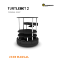
Figure 2.4 - The Turtlebot 2[7]!
!
!
!
!
!
!
!
8!
!
Figure 2.5 - HuroEvolution AD humanoid robot. Photo by RoboCup / Bart van Overbeeke!
9!
Figure 2.6 - Simplest middleware diagram!
!
!
!
!
!
!
10!
Figure 3.1 - IC to PC level communication diagram!
!
!
!
!
!
11!
Figure 3.2 - Proposed hardware architecture!
!
!
!
!
!
!
13!
Figure 3.3 - I2C bus electrical implementation!
!
!
!
!
!
!
14!
Figure 3.4 - Open drain line driver!
!
!
!
!
!
!
!
14!
Figure 3.5 - I2C arbitration example!
!
!
!
!
!
!
!
15!
Figure 3.6 - SPI bus electrical implementation! !
!
!
!
!
!
18!
Figure 3.7 - ATMega 328P PDIP package pin layout [21]!!
!
!
!
!
19!
Figure 3.8 - CAN bus electrical implementation! !
!
!
!
!
!
20!
Figure 3.9 - CAN bus line driver!!
!
!
!
!
!
!
!
21!
Figure 3.10 - CAN bus drive logic!
!
!
!
!
!
!
!
22!
Figure 3.11 - RS-232 electrical implementation! !
!
!
!
!
!
23!
Figure 3.12 - MCP2515 PDIP/SOIC pinout [40]! !
!
!
!
!
!
27!
Figure 3.13 - Timing diagram for CAN bit at 1 Mbps, using a 16 MHz clock source!
!
28!
Figure 3.14 - MCP2551 PDIP/SOIC pinout [33]! !
!
!
!
!
!
29!
Figure 3.15 - PCB Block schematic!
!
!
!
!
!
!
!
30!
Figure 3.16 - PCB Block board design! !
!
!
!
!
!
!
31!
!
!
!
!
32!
Figure 3.17 - An Arduino Uno board with an Ethernet shield!
!
ix
Figure 3.18 - Arduino shield board design!
!
!
!
!
!
!
33!
Figure 3.19 - CAN message structure! !
!
!
!
!
!
!
34!
Figure 3.20 - Roio header structure!
!
!
!
!
!
!
35!
Figure 3.21 - CAN buffers and protocol engine of the MCP2515 CAN controller [40]!
!
36!
Figure 3.22 - Roio message filtering flowchart! !
!
!
!
!
38!
Figure 4.1 - Diagram of a complete project using both Roio frameworks! !
!
!
45!
Figure 5.1 - The Hitec HS-311 servomotor [59]! !
!
!
!
!
!
52!
Figure 5.2 - Robotic arm diagram!
!
!
!
!
!
52!
Figures 5.3 and 5.4 - Inside view and lateral view of the robotic arm!
!
!
!
53!
Figure 5.5 - Servo arm static force diagram!
!
!
!
!
!
!
!
!
53!
Figure 5.6 - Servo arm geometrical representation!
!
!
!
!
!
54!
Figure 5.7 - Servo Control Board schematic!
!
!
!
!
!
!
56!
Figure 5.8 - Servo Control Board PCB! !
!
!
!
!
!
!
57!
Figure 5.9 - Adapted Servo Control Board!
!
!
!
!
!
!
57!
Figure 5.10 - Servomotor control signals!
!
!
!
!
!
!
58!
Figure 5.11 - USB bridge board!!
!
!
!
!
!
!
59!
Figure 5.12 - The sensor board, connected to the Roio prototype board! !
!
!
59!
Figure 5.13 - Sensor board firmware diagram!
!
!
!
!
!
!
!
!
60!
Figure 5.14 - Robot functional diagram - Native implementation! !
!
!
!
61!
Figure 5.15 - Native implementation GUI, running on Google Chrome 33.0!
!
!
62!
Figure 5.16 - Arm end position calculation!
!
!
64!
Figures 5.17 - 5.20 - Arm movement juxtaposed with its GUI representation !
!
!
65!
Figure 5.21 - Robot functional diagram - Client side implementation!
!
!
66!
Fig. 5.22 - Client side implementation GUI, running on Google Chrome 33.0!
!
!
67!
Figs. 5.23 - 5.28 - Robotic arm movement sequence!
!
!
68!
!
!
!
!
!
!
!
!
!
!
x
!
xi
!
List of Tables!
Table 3.1 - Truth table for collision arbitration in the CAN bus!
!
!
!
!
22!
Table 3.2 - Data transmission bus comparison! !
!
!
!
!
25!
Table 3.3 - CAN bit configuration for multiple bus bit rates!
!
!
!
!
40!
Table 3.4 - Overhead benchmark results!
!
!
!
!
42
!
!
!
xii
!
!
xiii
!
List of Acronyms!
BOM - Bill Of Materials!
CAN - Controller Area Network !
CRC - Cyclic Redundancy Check!
EIA - Electronics Industries Association!
GUI - Graphical User Interface!
HTML - HyperText Markup Language!
HTTP - HyperText Transfer Protocol!
I2C - IIC, Inter-Integrated Circuit !
IC - Integrated Circuit!
IDE - Integrated Development Environment!
JSON - JavaScript Object Notation!
PCB - Printed Circuit Board!
PDIP - Plastic Dual In-line Package!
PWM - Pulse Width Modulation!
QFN - Quad-Flat No-Lead!
SOIC - Small-Outline Integrated Circuit!
SPI - Serial Peripheral Interface !
TCP - Transmission Control Protocol!
USB - Universal Serial Bus!
!
!
xiv
!
Chapter 1 - Introduction!
1.1 Context!
The work that originated this dissertation started as part of the SocRob project and tem participating in
the RoboCup Middle Size League (part of Instituto de Sistemas e Robótica, Lisboa) hardware
development effort. The team has been participating in competitions since 1998, and the robots built
upon the current platform have endured several RoboCup[1] (a robotics competition with teams from all
around the world) and Festival Nacional de Robótica[2[ (a similar portuguese competition, with a
smaller scale) competitions, in which the robots suffer considerable damage.!
Although the team was producing significant developments as far as software was concerned, the
hardware efforts were hampered by general unreliability issues, resulting from wear and tear in parts
and circuit boards which were developed and updated over the years, usually with minimal
documentation. As expectable, the software development efforts also took a toll from this, resulting in
most of the testing being done in simulation environments, which then resulted in lackluster practical
results. !
Acquiring new robots was out of the question (due to the very high cost of new robots and the limited
budget the team had available), so it was decided to design of a new platform upon which the
development of new hardware could be made. Instead of a platform focused exclusively on robotic
football, a general purpose platform (adaptable for robotic football) would be the main goal. A
successful result would then provide not only a platform for the robotic football team, but also
platforms for other academic projects, which are almost always budget-constrained.!
1.2 Work Outline!
In order to produce a forward thinking, consistent, broadly applicable platform, the following objectives
were proposed:!
• Design of a robotics hardware framework, consisting of the hardware implementation of a low
level, distributed network for simple electronic systems, usable for both sensors and
actuators. This hardware should be inexpensive, simple to integrate into existing projects and
versatile enough to use for a broad set of applications.!
• Development of a software platform that abstracts the hardware implementation from the user
and takes care of all the scaffolding necessary to write code freely (middleware). This
middleware must allow a broad range of uses: from simple, quickly developed proofs-ofconcept where performance is mostly irrelevant, to extremely complex projects involving
considerable amounts of systems where performance and latency are critical.!
1
• Development of a simple robot, taking advantage of the strengths of the developed platform.
This consists of a 2 degree of freedom plus actuator robotic arm, where two different
approaches are demonstrated: one where the user relies on lower level code (targeted to a
developer capable of optimizing each part of the system), and one where the user relies on
higher level, more simple code (and can be mostly unaware of the complexity of the system).!
The framework should be given a name - from this point on, Roio will be used (chosen as an acronym
for RObotics I/O - although this does not describe all the capabilities of the framework).!
1.3 Motivation!
As will be shown in the next chapter, good robotics software development platforms exist, but they
aren’t paired with integrated hardware development platforms. Many robots already have packages to
allow for ROS integration, and some are developed with ROS integration in mind from the get-go, as
was the case with the Turtlebot. Those are good robotic software development platforms, but they are
very limited in terms of hardware development, as these robots are not hardware development
platforms themselves. The scaffolding ROS provides on the software side is not present on the
hardware side. This means that developing hardware on top of an existing robot consists of adding an
isolated system that uses a different architecture from the one present in the robot itself.!
Moreover, most robots hardware implementations are largely incompatible with each other. For
example, the three robots presented in the next chapter use very different communication protocols
and architectures on the hardware side. Even though it would be possible to transfer hardware from
one to the other, it would not be a simple adaptation, and would require architectural modifications.!
The leads to the first objective stated for this project:!
• Design of a robotics hardware framework, consisting of hardware implementation of a low
level, distributed network for simple electronic systems, usable for both sensors and
actuators. This hardware should be inexpensive, simple to integrate into existing projects and
versatile enough to use for a broad set of applications.!
The need for this is now clear, and this will be the focus of the third chapter of this dissertation.!
However, this work will also focus on developing a new software framework. This framework will have
a different approach to the modern robotics middleware described in the next chapter. First of all, while
ROS is extremely efficient for advanced robotics development projects, there is a quite steep learning
curve associated with it if the user isn’t already well versed in the field. The installation process alone
can be intimidating for an engineering student in the first years of college.!
Another feature that is often overlooked in most robotics frameworks is graphical user interface
development tools. Often, when in a pure investigation environment this is not strictly necessary. But it
2
does make many of the maintenance and development tasks easier, provides help when analyzing the
behavior of the robot and can enable complete new ways of interacting with the robot. Given that the
popularity of web-enabled devices has been rising continuously over the last years[13][14], it makes
sense that, if a GUI is enabled, it is web-based and mobile aware, in order to provide the maximum
compatibility with multiple devices with the least amount of development effort.!
1.4 Work Structure!
This work is composed of six chapters.!
The first chapter contains an introduction, including the context, motivation and work outline for this
thesis. !
The second chapter provides background and information useful for the reader to understand the
context in which this work was developed, as well as an analysis of the state of the art solutions
available at the time of writing.!
The third and fourth chapters cover the development of the hardware system supporting the robotic
platform, as well as its software counterpart.!
The fifth chapter covers the construction and deployment of a simple robot, consisting of a robotic 3axis robotic arm, using two different approaches that exemplify the different types of users that might
take advantage of the platform developed as part of this dissertation.!
A sixth chapter presents the conclusions and the possible future improvements that were identified in
the development of this project.
3
!
4
Chapter 2 - Background!
2.1 State of the Art!
2.1.1 Hardware!
All but the most simple robots shouldn’t be examined as a single unified entity. A robot is more akin to
a group of independent systems, each with its own purpose, controlled by one or more pieces of
software. The systems can be classified as either sensors (e.g.: a camera) or actuators (e.g.: a motor).
Depending on the type of robot, the software can fulfill two different purposes:!
• On an autonomous robot, the software obtains inputs from the sensors and converts those
inputs into instructions to the actuators. This may be as simple as an if / then clause (as in a
line-follower robot), or an extremely complex process involving decision taking and inter-robot
communication (as in a football player robot) - Fig. 2.1.!
User
Decision
Making
Sensor
Software
Actuator
Hardware
Fig. 2.1 - Autonomous robot diagram!
• On a human-operated robot, the software will obtain inputs from the sensors and relay them
to a human, which then instructs the actuators. The software may translate the sensor values
before presenting them, and translate the human inputs before relaying them to the actuators
(e.g.: converting the signals from a game pad into acceleration values suitable for a motor
controller) - Fig. 2.2.!
Decision
Making
User
Software
Sensor
Actuator
Hardware
5
Fig. 2.2 - Human-operated robot diagram!
!
Some robots may also be a hybrid, switching between autonomous and human-operated as
necessary, as is the case of the ISR Raposa[3], a search-and-rescue robot.!
As of the time of writing, the two approaches to developing a robot’s hardware consist of the DIY route
- building everything from scratch - or buying a pre-made robot. If the latter is chosen, a fullycustomized robot may be bought (as was the case with the SocRob OMNI robots used by our robotic
football team) or a simple robot may be bought and adapted to the needs of the project. A generic
robot benefits from mass market economics, and is thus much cheaper to acquire, but may require
extensive (and expensive) modifications for some projects. However, given the monetary constraints
most academic projects operate in as of lately, buying a robot (or, as necessary for a robotic football
competition, a team of highly advanced robots) is often unthinkable right from the beginning.!
2.1.2 Custom made robot: SocRob OMNI!
As mentioned earlier, the project that started this thesis consisted of finding a successor to the
SocRob OMNI platform (below), the robots that the ISR SocRob Robotic Football team used as
players.!
Camera assembly
Laptop
Kicker / Dribbler
Chassis
Wheel and Motor
Fig. 2.3 - A SocRob OMNI robot!
6
This platform consists of an omnidirectional (hence the name) autonomous robot, has been in
development since 2004, and in use since 2006[4]. Given its use, its hardware had been upgraded
over the years, as a result of student’s work (and necessity). This meant that the robot does not have
a driving architecture, parts are mounted as necessary. The main components labeled in Fig. 2.3 are:!
• Camera assembly: This structure is mounted on three poles, in order for the camera (inside
the enclosure at the top) is able to have an unobstructed view of the field. This camera has a
fisheye lens mounted, in order to cover as much of the field as possible. Given the
advantageous position this assembly offers in terms of electro-magnetic interference (no other
part of the robot is as far away from the motors and kickers) this enclosure was also used for
the installation of a compass.!
• Laptop: The laptop is used to run all the software that the robot needs to work. This includes
image processing, decision-taking, behaviors and interfacing with all sensors and actuators.
In this case, each hardware module is connected to the laptop directly, using USB or firewire.!
• Kicker and dribbler assembly: Each robot possesses an electromagnetic kicking system and a
dribbling system. The former uses a capacitor bank to store energy; this energy is then
discharge on a short burst through a solenoid with a ferromagnetic plunger inside. This
causes the plunger to accelerate rapidly and hit the ball, effectively kicking it. There are two
types of dribblers available: a passive dribbler (pictured), which consists of 4 metallic fingers
to keep the ball stable when the robot is moving, and an active dribbler, which uses a moving
rubber roller to control the ball much more accurately[5].!
• Wheel and motor assembly: The robot uses 3 omnidirectional wheels to propel itself, each
powered by a 90 W Maxon Brushed DC Motor.!
• Chassis: The base of the robot consists of a circular aluminium chassis, painted black, upon
which all components are assembled. Two 12 V NiMH 10 Ah batteries are contained inside,
as well as all the kicker and dribbler electronics, motors and motor controllers.!
This is a highly specialized robot, developed with a very specific purpose in mind. The software has
also been custom made (mostly out of students’ work, as well, with the same caveats mentioned
earlier) and will be further analyzed later in this work.!
2.1.3 Generic robot: Turtlebot!
The Turtlebot is a general-purpose robot developed by Willow Garage. Willow Garage is a team of
robotics experts focused in developing hardware and open-source software to be used for research
and development in the robotics field[6]. Among other things, they also developed ROS (Robot
Operating System), which is an open-source OS-like robotics framework, very widely adopted in the
field. The Turtlebot was conceived with ROS support from the beginning, and is widely available for
sale as a complete robot or a kit, so it is a extremely good example of the state of the art in off-theshelf generic robotic platforms. The last version of the robot itself is in Fig. 2.4.!
!
7
Kinect assembly
Laptop Assembly
Kobuki platform
Fig. 2.4 - The Turtlebot 2!
The robot consists of 3 main parts:!
• Kinect assembly: The Turtlebot ships with a Microsoft Kinect and the necessary assembly and
cables to mount it on top of the other components.!
• Laptop assembly: The Turtlebot was designed to be controlled by a laptop running ROS, so a
laptop tray is mounted right over the base platform. The laptop connects to the Kinect via a
custom USB cable (this “Y” cable is used to provide the Kinect with power from the base
platform but to route the data to the laptop) and to the base platform through a second USB
cable. When included in the package, the laptop is typically an ASUS EEE 1215N.!
• Kobuki base platform: All of the components assemble into this base platform. It is, in fact, a
Kobuki - a very simple mobile computing platform, that may be acquired separately[8] from the
Turtlebot itself. It uses two 9W 12V Brushed DC motors, with the wheels mounted in parallel
on opposite sides of the robot, to provide the ability to turn the robot using differential steering,
and has three bumpers in the front of the enclosure, used to detect collisions. It contains a
14.4 V 2.2 Ah Li-ion battery, used to power the robot. It also provides a gyroscope, motor
odometry, a buzzer and 3 LEDs and 3 buttons[9].!
Willow Garage makes available a version of ROS adapted to the Turtlebot, so the software is also a
general-purpose solution. This will also be looked into with more detail ahead.!
!
8
2.1.4 HuroEvolution AD!
This third robot is chosen in order to provide a different approach to a mobile robot - a humanoid robot.
The HuroEvolution AD robot was developed at the National Taiwan University of Science and
Technology[63], and it was both the best team in the round-robbin stage and second-place in the
elimination stages of RoboCup 2013 Humanoid League. It is a 149 cm tall, 15 kg humanoid robot[63].!
Camera assembly
Control Electronics
Servo-based joints
Fig. 2.5 - HuroEvolution AD humanoid robot. Photo by RoboCup / Bart van Overbeeke!
Its main components are labeled in Fig. 2.5:!
• Camera assembly: The assembly consists of a simple USB camera, mounted on top of a
rotating servomotor-driven platform.!
• Control electronics: The main component of the control electronics is a small-factor barebones
Intel Atom-based computer, where most software is run, and to which all sensors (the camera
and a gyroscope) and actuators are connected. An ATmega 1281 based board (connected to
the computer) is used for motion control and RS-485 communication to all servos.!
• Servomotor-based joints: These are the only actuators the robot possesses, and are used
both for locomotion and world interaction.!
This third robot is also highly specialized, and consists of a mix of ready-made parts (such as the
servos and the control boards) with purpose-built parts (such as the servomotor-based actuators).!
2.1.5 Software!
On the software side, robotics software usually consists of at least two levels. These two levels are the
middleware and the application code itself. Although middleware in general has a broader reach[10],
the simplest form of middleware in robotics usually consists of a simple isolation layer, to shield the
9
software developer from the architecture of the hardware underneath and the communication
protocols used to interface with it (hardware abstraction).!
Behavioral
Code
Software
Middleware
Sensor
Actuator
Hardware
Fig. 2.6 - Simplest middleware diagram!
This is useful in order to make application code reusable in different robots, and has the side-benefit of
making the substitution of the application code easier. However, most of the boilerplate code
necessary to produce a functioning system is still left up to the programmer producing the application
code, which is sub-optimal in any circumstance, even worse in a research and education project
where most efforts are developed by different persons in 12 month spans. It makes sense then, for the
middleware to assume more functionality. !
In the research community, one software platform has emerged in the last years as the single most
deployed solution for robotics projects[11]: ROS. ROS assumes the posture of mimicking an operating
system: providing inter-process messaging foundations, tools to build and run code across computer
clusters and package management[12], apart from hardware abstraction. Given the wide adoption of
ROS, packages are already available for a multitude of common purposes and algorithms used in the
field. These characteristics, the name (Robot Operating System), and the language used by some
distributors has led to the idea that ROS is an operating system, when in most cases it is ran over a
linux distribution, the most common being Ubuntu.!
Given these premises, a modern robotics middleware can be defined as a software foundation
providing at least the following features (by order of relevance):!
• Robotics hardware abstraction;!
• Inter-process communication;!
• Package management.!
!
10
Chapter 3 - Hardware: The Roio
Network!
3.1 Robotics hardware architecture!
As stated in the second chapter, a robot consists not of a single entity, but a group of systems,
coordinated by a piece of software. This means that there must be, at least, some form of
communication between the systems and the software. In fact, there are usually at least two levels of
communication, as micro-controllers are used to interact with the devices and ICs used as sensors
and actuators, and the micro-controllers then report to a PC. This means the diagrams used in earlier
chapters were simplified. A more detailed diagram (pertaining to the hardware implementation only) is
presented in figure 3.1 below.!
Sensor
PC
μController
μController
μController
Sensor
Actuator
Sensor
Actuator
Fig 3.1 - IC to PC level communication diagram!
The communication between the microcontroller and the various sensors and actuators is strictly
dependent on the device itself - there is little to no margin for improvement in this layer, apart from
providing specific libraries and hardware implementations for each sensor or actuator. However, the
architecture of the layer between the microcontroller and the PC is entirely up to the developer. The
architecture presented above, however, has several problems, the most hindering of them being:!
• Each microcontroller’s communication protocol must be implemented separately (mostly over
RS-232 converted to USB using a second IC, or directly through USB). As each system
typically has a specific purpose (e.g. a motor controller) the protocol tends not to be re-usable.
This also has the implication of forcing the software developer to be aware of the hardware
implementation of the systems.!
• The microcontrollers won’t be able to communicate with each other, unless a second physical
connection is established between them and a specific protocol for that communication is
11
implemented or the messages between the two ICs are routed through the software layer
from the origin to the destination.!
It is clear that developing a standard for this layer would improve the celerity with which the systems
could be developed and implemented, and improve the overall quality of the systems themselves
given that any improvement to the layer implementation would then be applicable to all systems using
it. This chapter, then, will focus on creating this network layer. !
3.2 System Design!
The point of this network are to correct the problems with the typical architecture presented above. As
such, the following features have been identified as necessary:!
1. Allow bidirectional data transmission between the PC and the microcontrollers and between
each of the microcontrollers;!
2. Allow for low latency communication with message prioritization (extremely important for
correct motion control, for example);!
3. Allow for, at least, 20 independent systems to be connected to this network and enough
bandwidth for simple messages to be sent by all 20 devices (this number would enable the
construction of any of the robots mentioned before - although ideally the chosen network
should allow for more devices to be used, in order to provide future growth margin) at least
60 times per second (60 Hz update rate). !
4. The hardware implementation must be inexpensive, in order to be usable in projects of all
sizes (and budgets) - a maximum of €5 per board is set as a reasonable target;!
5. The hardware implementation must be physically small, in order to keep circuit board area
low - size is proportional to the manufacturing cost of the board. The target would be to fit a
simple microcontroller implementation and all networking electronics on a 5x5 cm dual layer
PCB, as this is the most common very low cost board;!
6. The system must be resilient enough to handle operation inside a robot’s chassis, near
moderate noise sources (such as electric motors);!
7. Provide power for simple low energy consumption systems (e.g. simple sensor ICs and
microcontrollers), to simplify the internal wiring of the robot as much as possible; !
8. Firmware (for the microcontroller) and software libraries must be developed in order to
provide a flexible and simple API;!
9. Present to the PC a standard interface, preferably using a single USB port;!
10. The firmware library must consume as little processing power and memory resources as
possible, as microcontrollers are typically extremely limited in both areas;!
These are ambitious goals, and in order to keep the scope contained some limitations should be
enforced. First of all, the network will be developed solely for simple low-level messaging, and not for
12
high-bandwidth applications (e.g. a camera). Secondly, the hardware implementation will target a
single platform: the Arduino. !
The Arduino is an open source electronics development platform. This project revolves around
inexpensive ATMEL microcontroller development boards, and includes the full stack of tools from IDE
to the bootloader[15][16]. The development board exposes multiple analog and digital pins to the user, as
well as several digital communication interfaces, including USB (through an RS-232 converter IC[17] or
natively[18], depending on the model. An IDE is included, and it is provided for Mac OS X, Windows
and Linux, the three most important operating systems as of the date of writing. The pre-programmed
bootloader allows for the programming of the boards through the USB connection using the IDE itself,
without requiring any sort of protygraming devices. Code is written in a simplified variant of C, though
the user can use lower languages (even assembly) interchangeably, if necessary.!
There is a very large community developing around this open-source platform - for example, all of the
hardware developed for the SocRob platform in recent years has been developed on Arduinos, and
the final PCBs produced for competition use are Arduino-compatible. It is also widely available both in
kit as in pre-built form. This makes it the perfect target platform for this project.!
Given these premises, a new hardware architecture can be specified:!
Software
Module
μController
Sensor
Software
Module
μController
μController
Sensor
Actuator
Actuator
Fig. 3.2 - Proposed hardware architecture!
The major difference, when compared to the architecture in Fig. 3.1, is the use of a single bus through
which all systems communicate as equals. The software side is also able to send messages to this
same bus, so this must also be implemented - that will be the focus of chapter 4. Given the multitude
of data bus implementations already in existence, it makes no sense to develop a new one from the
start. Instead, 4 existing protocols will be analyzed as to the compliance with the features laid out in
the beginning of this sub-chapter, and the network will be developed on top of the one that fits the
purpose of this work best. !
13
The first two choices for review are I2C (Inter-Integrated Circuit) and SPI (Serial Peripheral Interface).
Both of them are available on the ATMega 328P and ATMega 32u4, the microcontrollers used on the
Arduino UNO and Leonardo, respectively, without the use of any external hardware, and they are both
in widespread use. The third choice falls onto CAN (Controller Area Network), which is not widely used
in robotics but is in extremely wide use in the automotive industry. The fourth entry will be RS-232.
Although the characteristics of this protocol seem like a poor fit for this project, it is included as a term
of comparison to the type of architectures this work is trying to displace.!
3.2.1 I2C!
I2C - Inter-Integrated Circuit - is a widely used synchronous serial data transmission interface. It was
developed by NXP Semiconductors (still known as Philips Semiconductors, at the time), and more
than 50 companies fabricate ICs compliant with this protocol[20] nowadays, one of them being Atmel
Corporation, the company responsible for the fabrication of the microcontrollers used in the Arduino
platform. In fact, the ATMega 328P and 32u4, used in the latest Arduino models, include hardware
based I2C support[21][22].!
The I2C bus is implemented as a simple 2 line serial bus:!
SDA
SCL
Device
Device
Device
Fig. 3.3 - I2C bus electrical implementation!
The SDA line is the Serial DAta line, and the SCL is the Serial CLock line. Both lines use the same
high and low voltages. Although the specification allows for several different voltages, most ICs
implement the bus using 5 V / 0 V or 3.3 V / 0 V as High / Low voltages. Both lines are implemented
on the client devices as open-drain lines (the output stage of the I2C device is terminated by an
transistor with a grounded source and the drain exposed as the output of the device).!
+5V
Pull-up
Resistor
SDA
D
G
D
G
S
D
G
S
S
Fig. 3.4 - Open drain line driver !
14
To provide the bus high-level, a pull-up resistor is necessary. It follows that an output driver on any of
the two lines can only ensure the line to be low, not high. This will be used for arbitration, which will be
discussed later.!
Pull-up resistor sizing is dependent on capacitive load present on the line; buffers and/or multiplexers
are usually necessary once a considerable number of devices is added to the bus (the number
depends on several factors that affect the bus capacitance, such as the quality and length of the
cables and connectors used to link the multiple PCBs to the bus, the design of the PCBs themselves
and the actual silicon implementation of the bus drivers in each device, as well as the electro-magnetic
interference caused by the surrounding environment).!
The protocol follows a multi-master architecture, assigning the master device dynamically, and
collision detection and arbitration are included in the specification in order to avoid data corruption due
to simultaneous transmission attempts. When a device is transmitting a message all other devices’
outputs will be in a high-impedance state. A collision may happen if two devices try to send a message
at the same time. Arbitration works by simultaneously monitoring the SDA line as the device is
transmitting its message. As a device can only pull the line low, not high, due to the open-drain output
driver implementation, a device will detect a collision only when it tries to impose a high level on the
line when a second device tries to set a low level, as this will result in the line being pulled low.!
A
0
!
1
2
Device 1
3
4
Device 2
5
6
SDA
Fig. 3.5 - I2C arbitration example!
Figure 3.5 illustrates an arbitration occurring. For the first three cycles of the transmission, devices 1
and 2 both try to transmit the same data, so none of them realizes the collision. However, in cycle A,
they try to send a different bit. At this point, device 1 acknowledges the loss of priority, backs off from
trying to transmit and sets its output as high impedance. It will retry to send the message as soon as
the bus is freed. As the first data to be transmitted on a message is the destination address, the
arbitration scheme effectively prioritizes messages sent to devices with a low address value.!
Each device on the bus has an address, consisting of a 7- or 10-bit value. In order to allow for interoperation of devices fabricated by different parties, NXP manages and attributes addresses on
request. There are, however, costs associated with obtaining an address (of range of addresses). In
15
order to save costs and complexity, most companies produce devices capable of assuming only a
limited number of addresses, which limits the number of devices of the same type that can be placed
on the bus.!
A different problem arrises from the fact that both microcontrollers used in the last versions of the
Arduino are only capable of managing a single I2C bus. I2C sensors are extremely common; the use
of a single I2C interface means that all devices in a robot would share the same bus both for intersystem communication and microcontroller to sensor communication, which is not acceptable - it
would lead to unnecessary bus usage and higher likelihood of addressing collisions (effectively forcing
all devices on the bus to be aware of every I2C device in the robot). The solution to this problem would
be to provide a software implementation of the I2C bus to implement the network on. This implies a big
tradeoff though - the consumption of part of the processing power and memory availability of the
microcontroller for the implementation of the network. The electrical implementation would also be
hindered by the loss of the dedicated hardware - noise suppression would be lost (the regular pins on
the microcontroller do not have this circuitry), as would multi-master arbitration (the microcontroller
pins are not implemented as open-drain, they are capable of pulling the line up or down as necessary,
which destroys the arbitration protocol).!
One of the most important factors in this project is the data throughput provided by each technology.
The bandwidth required to achieve the throughput qualitatively specified in goal 3 using the I2C bus
can be obtained from:!
T = fupdate × ndevices × (M + Ov addr + Ov bus )
(1) !
Where T is the network throughput, fupdate the number of messages sent per second per device, ndevices
the number of devices present on the bus, M the message size (in bits), Ovaddr the addressing
overhead imposed by the network protocol being developed and Ovbus the overhead imposed by the
bus addressing and flow control mechanisms. For the purposes of this sub-chapter, an average 6 byte
message length will be considered, as well as a minimum of 8 bit addressing space for the destination
and source devices. As stated above, the I2C bus allows for 7 or 10 bit addressing modes, which
impose a 8 or 16 bit overhead in each message. Given that there are reserved address spaces, and
the addressing may be constrained by other devices present on the bus, the calculations will assume
10 bit addressing is used, and values will be obtained for a scenario (A) in which 8 bits of I2C bus
addressing space can be used by the network protocol, and for a scenario (B) where all 16 bits must
be implemented in the bus messaging space. At the beginning and end of each message a START
and STOP signal is transmitted, respectively. Additionally, an acknowledge signal is transmitted by the
destination device every 8 bits, lasting an additional cycle. From this we obtain, for scenario A:!
T = fupdate × ndevices × (M + Ov addr + Ov bus ) = 60 × 20 × (6 × 8 + 8 + (16 + 8 + 2)) = 98.4 kbps !
And, for scenario B:!
16
T = 60 × 20 × (6 × 8 + 16 + (16 + 9 + 2)) = 109.2 kbps !
The ATMega microcontrollers being targeted by this work support both 100 kbps and 400 kbps
operation, so both scenarios all well within the capabilities of the bus. The number of devices that
would generate 100% utilization of the bus can be obtained from:!
ndevices =
R
fupdate × (M + Ov addr + Ov bus )
(2) !
Where R is maximum bit rate of the bus. Considering R = 400 kbps, and the worst case scenario (B):!
ndevices =
R
fupdate × (M + Ov addr + Ov bus )
=
4 × 10⁵
60 × (6 × 8 + 16 + (16 + 9 + 2))
≈ 73 devices !
3.2.2 SPI!
SPI - Serial Peripheral interface - is a synchronous serial data transmission interface. It was created
by Motorola in the mid 1980’s as general-purpose interface for its microcontrollers to communicate in a
standardized manner with peripheral devices, such as EEPROMs[23]. It is also natively supported (in
hardware) by both the ATMega 328P and 32u4, as well as many other microcontrollers in Atmel’s
catalog. It should be noted, however, that there is no single strict specification maintained by a central
entity, each manufacturer presents its own (similar) implementation.!
It has many similarities with the I2C bus presented above. They are both serial (data is transferred in
series, one bit at a time), synchronous data transmission protocols. They are also master-slave
protocols. However, their implementation is significantly different. The major difference come from the
slave selection mechanism. Where I2C places addressing in the data line, and relies on the listening
devices to realize when a message is targeted to them, SPI uses a dedicated line to make the
destination device aware that the data is being sent to it. !
An example physical implementation of an SPI bus is pictured in the following page.!
!
!
!
!
!
!
17
!
Slave
Master
Slave
Slave
SCK
MOSI
MISO
Slave Select
Fig. 3.6 - SPI bus electrical implementation!
The bus itself consists of three lines, SCK, MOSI and MISO. SCK (Serial ClocK) is the clock signal.
This clock is controlled by the master device only. MOSI stands for “Master Output, Serial Input”. This
line is used to shift data from the master to the slave device. The third line, MISO, is used for the
opposite, to shift data from the slave to the master device (“Master Input, Serial Output”). This means
that the SPI bus allows for full duplex data transfers, an advantage when compared to the I2C
interface.!
However, a fourth line is present - the Slave Select line. In fact, for each slave present on the bus, the
master must provide a Slave Select line. This is used to signal to the corresponding slave that the bus
is now dedicated to communication between the former and the master device. This is usually active
low, and referred to in documentation as SS . The presence of the dedicated line for attention
signaling makes it possible to avoid introducing addressing in the SPI bus, and the overhead
associated with it. It also nullifies the need for collision avoidance and arbitration, as there is a single
source of truth in the master device maintaining synchrony between all nodes.!
There are, however, disadvantages to the SPI bus. The first one stems from the electrical architecture
itself: it forces the network to have a centralized architecture, with a single master device controlling all
flow of information. This makes it hard to achieve goal 1 - allow bidirectional data transmission
between the PC and the microcontrollers and between each of the microcontrollers - without some
form of workaround. The most obvious solution would be to have a master microcontroller polling each
of the devices and distributing messages as necessary. This would however come with two with two
distinct disadvantages:!
18
• There would be an increase in microcontroller resource consumption, as the device would be
forced to frequently stop its normal operation to respond to the master device;!
• As the slave devices are being polled in sequence, a polling latency is introduced.!
Another disadvantage is the Slave Select line. It makes the SPI bus have an extremely low overhead,
but each slave device requires a dedicated line, the master device must have enough I/O pins to
operate all devices. The PDIP version of the ATMega 328P controller is presented below:!
Fig. 3.7 - ATMega 328P PDIP package pin layout [21]!
This controller is used on the Arduino Uno (most older models, including the very common Arduino
Duemilanove[24], used this microcontroller or the ATMega 168P, which has the same pin layout for the
PDIP package, as well). Pins 7, 8 and 20-22 are used to provide power to the microcontroller, pin 1 is
the RESET pin and is highly advisable to use it as such, and a crystal oscillator is connected to pins 9
and 10. Pins 17-19 are reserved for use with the SPI bus. This leaves only 17 pins available, meaning
that, without additional hardware, only 17 devices could be connected to the master microcontroller.!
A last problem is shared with the I2C bus: there is a vast number of sensors and other helper ICs (SPI
I/O expanders and EEPROMs being particularly common) using the SPI bus, and the microcontrollers
being targeted in this work are capable of operating a single SPI bus.!
The SPI bus is capable of operating at much higher transmission speeds than the I2C bus. The
ATMega 328P and 32u4, in particular, are capable of clocking the SCK line at half the operating
frequency of the microcontroller[21][22]. Given that, in the Arduino, both of them are clocked at 16 MHz,
the SPI bus would be able to operate at 8 MHz. As there is no addressing overhead, there would be
an effective 8 Mbps full-duplex data rate available for data transfer. This is a much higher rate than
would be necessary for the implementation of the proposed network - in fact, following the same
rationale as used for the I2C bus of 6 byte messages sent by every device 60 times per second, the
required throughput to achieve goal 3 would be:!
T = fupdate × ndevices × (M + Ovaddr + Ovbus ) = 60 × 20 × (6 × 8 + 16 + 0) = 76.8 kbps !
And the bus would reach 100% utilization with !
19
ndevices =
R
8 × 10 6
=
≈ 2083 devices !
fupdate × (M + Ovaddr + Ovbus ) 60 × (6 × 8 + 16 + 0)
Which is approximately 28 times what could be achievable with the I2C bus. It should be noted,
however, that the SPI interface is not limited to 8 bit words - any number of bits may be transferred in a
transaction.!
!
3.2.3 CAN!
The CAN (Controller Area Network) is a multi-master bus standard developed throughout the 80s by
BOSCH GmbH, as a cost effective communication protocol for the automotive industry[25]. Of the four
protocols under analysis (I2C, SPI, CAN and RS-232), this is the only one not supported natively by
either of the target microcontrollers. However, given the ubiquitous use in the automotive industry
standalone CAN controllers are inexpensive and readily available from electronics suppliers[26][27][28].!
The electrical implementation of the CAN bus is quite different from both I2C and SPI. A representation
of a CAN bus is pictured below.!
Device
Device
CANH
Device
CANL
Fig. 3.8 - CAN bus electrical implementation!
Two lines are used in the CAN bus: the CANH and CANL lines (CAN High and CAN Low,
respectively). These lines are implemented as a twisted pair and driven differentially in order to obtain
higher noise resilience - as stated above, CAN was originally designed to be used in automotive
applications, so it must be able to withstand the considerable electromagnetic noise sources present in
a motor vehicle (e.g. starter motors, spark plug ignition systems and alternators). This is accomplished
due to the noise affecting both lines in the same form (considering that the twisted pair is not uncoiled
and separated at any point):!
Output = (CANH + η ) − (CANL + η ) = CANH − CANL
(3) !
Where η represents the noise induced in the bus lines. !
20
In order to improve noise resiliency even further, all CAN messages contain a 15 bit Bose-ChaudhuriHocquenghem CRC. Using 6 bytes of data as an example, the chosen code is capable of detecting all
corrupted messages containing 5 random bit inversions or less, burst errors of 15 bit or less[29][30]. !
For the purposes of this work, the Hi-Speed variant of the CAN physical implementation will be
considered. This variant operates from a 5 V power supply, and a maximum speed of 1 Mbps can be
obtained[31]. The CANH line goes from a minimum value of 2.5 V to a maximum of 5 V minus the
voltage dropped across the output line driver (typically ≈ 0.5 V), and the CANL voltage will go from a
minimum of 0 V plus the voltage dropped across the output line driver (also typically ≈ 0.5 V) to 2.5
V[32]. The voltage differential between the two lines will then have a maximum of ≈ 4 V to a minimum of
0 V.!
Both lines are passively pulled up to 2.5 V - this is internally implemented in the driver ICs. The output
drivers are only capable of forcing the CANH line to its high level and the CANL line to its low level these are usually implemented as an open-source / open-drain driver pair driving the CANH and CANL
lines[33][34][35], respectively, as pictured below:!
+5V
+2.5V
S
Driver High
G
D
CANH
CANL
D
Driver Low
G
S
Fig. 3.9 - CAN bus line driver!
This is taken advantage of in order to implement a non-destructive arbitration and collision avoidance
scheme, similar to what’s used in I2C. From the implementation described above, the dominant state
will be the one where the voltage differential between the two bus lines is at its highest level. Inverted
logic is used, which means a logic one is represented by the minimum voltage differential, and a logic
zero is represented by the maximum voltage differential, hence the bus will be zero dominant. The
complete representation of a bus driver input and output logic is represented in the next page.!
21
CAN Driver High
Data Out
CAN Driver Low
Data In
+
CANH
-
CANL
Fig 3.10 - CAN bus drive logic!
As is the case with I2C, arbitration works by simultaneously monitoring the data captured from the bus
as the device is transmitting its message, and detecting a collision when it tries to impose a logic one
on the line at the same time a second device tries to set a logic zero (see figure 3.6, page 16). The
difference in this case is the electrical implementation. A truth table with all the possible output states
assumed by two devices is presented below (considering perfect output drivers capable of outputting
5V on the CANH line and 0 V on the CANL line):!
Device 1
Device 2
OUT 1 H
OUT 1 L
OUT 2 H OUT 2 L
CANH CANL
Result
0
0
5V
0V
5V
0V
5V
0V
0
0
1
5V
0V
2.5 V
2.5 V
5V
0V
0
1
0
2.5 V
2.5 V
5V
0V
5V
0V
0
1
1
2.5 V
2.5 V
2.5 V
2.5 V
2.5 V
2.5 V
1
Table 3.1 - Truth table for collision arbitration in the CAN bus!
A CAN message starts with the identifier field (meant to be used as a message identifier). This means
that this arbitration scheme will implement prioritization of messages with the lowest identifier field
values, as was the case with I2C. This field can have two lengths, 11 or 29 bits. A “standard frame”
message contains a 11 bit address, and an “extended frame” message uses a 29 bit address instead.
The CAN specification contains the requirements for message filters and masks, meant to provide a
way to specify which messages should be passed from the CAN controller to the microcontroller itself
for processing, and these apply to the identifier field. This capability, if fully implemented by the CAN
controller, makes it possible to implement part of the network protocol without using up microcontroller
resources. Hence, extended frames will be considered from this point on, as these provide the
maximum flexibility for the network protocol implementation if CAN is chosen, and all addressing
overhead can be contained inside this identifier.!
Apart from the 29 bits per message already explained, another 9 bits per message are consumed with
control data (e.g., identifier type, data length), and 11 bits are consumed by message start, end and
22
acknowledgement signaling. The CRC takes up an additional 15 bits. Between each message a 3 bit
“Inter-Frame Space” must be inserted. The throughput required for the target of 60 messages per
second for 20 devices, with 6 bytes each would amount to:!
T = fupdate × ndevices × (M + Ov addr + Ov bus ) = 60 × 20 × (6 × 8 + 0 + (29 + 9 + 11+ 15 + 3)) = 138 kbps !
Considering operation at 1 Mbps, the maximum number of devices operating on the bus would be:!
ndevices =
R
1× 10 6
=
≈ 145 devices !
fupdate × (M + Ovaddr + Ovbus ) 60 × (6 × 8 + 0 + 67)
!
3.2.4 RS-232!
RS-232 (now called EIA232, and commonly referred to as Serial, although many other serial protocols
exist) was developed by the EIA (Electronic Industries Association) and introduced in 1962 as a way to
standardize an interface standard for data communications equipment[36]. The connection between a
modem and a computer terminal was one of its most widespread uses, and dictates many of its
features - connection control and signal encoding functions, for example. Unlike the other protocols
analyzed so far, it was designed exclusively as a point-to-point data transmission interface, not a multidevice bus. It is also an old standard with some problems (high noise susceptibility, low data rates,
very limited transmission length[36]), but it is provided by nearly all microcontrollers, its implementation
is very low cost and it is the protocol used nowadays in the SocRob architecture (and many other
robots) for most microcontroller to PC communication (there is usually not a physical RS-232 line
anywhere on the robot, though; in most cases a RS-232 to USB converter is included in the
microcontroller PCB - as is the case for the Arduino Uno - or the microcontroller emulates RS-232 over
USB directly - as is the case for the Arduino Leonardo). It makes sense, then, to analyze it only as a
point of comparison.!
The specification defines several bus lines, but most common implementations rely on only two
connections: a transmit line (TX) and receive line (RX), cross-wired between two adjacent devices:!
!
TX
RX
Device 1
Device 2
RX
TX
23
Fig. 3.11 - RS-232 electrical implementation!
Theoretically, both line should operate between 5 to 15 V and - 5 to -15 V at the output, and 3 to 15 V
and -3 to -15 V at the input. However, the specification admits voltages up to ± 25 V[36], in order to
increase compatibility with devices that do not adhere completely to the standard. The lines are driven
asynchronously - there is no clock line present. The specification does not mandate a maximum
transmission speed, only a maximum slew rate of 30V/µs; in practice, this limits the line speed to 120
kbps[36].!
Being a simple point-to-point interface, the bus implies no message overhead, and only the
addressing overhead is necessary. The throughput required for the target of 60 messages per second
for 20 devices, with 6 bytes each can be obtained from:!
T = fupdate × ndevices × (M + Ov addr + Ov bus ) = 60 × 20 × (6 × 8 + 16 + 8) = 86.4 kbps !
Considering the maximum data transmission rate the Arduino is able to use, 115200 bps:!
ndevices =
fupdate
R
115200
=
≈ 26 devices !
× (M + Ov addr + Ov bus ) 60 × (6 × 8 + 16 + 8)
RS-232, as described so far, cannot be used as the base for the projected network, as it only allows
for data transmission between two devices. In order to connect multiple devices, they must be either
daisy-chained (which implies that a message must pass through all the devices connected before the
destination device) or connected to a central hub device. The first alternative has the problem of
requiring a second RS-232 interface in each device (which must be implemented in software, as both
target microcontrollers provide only one interface), and the fact that messages must travel to all nodes
before the destination introduces processing overhead associated with the passthrough and analysis
of the messages and latency. The second alternative requires a relatively powerful central node, and
the resulting architecture is not compatible with the goals for this project, as it requires all messages to
go through a central node.!
RS-232 then, as predicted, is not a good fit for the proposed network architecture.!
!
!
3.2.5 Comparison!
Following the analysis detailed in the former four sub-chapters, two of the technologies - SPI and
RS-232 - can be excluded, as the capabilities they provide are not in line with the requirements set out
beforehand. This leaves I2C and CAN as possible choices. In order to summarize the information
provided so far, a comparison table is presented in table 3.2.!
24
Goal
1 - Direct bidirectional data
I2C
Yes
between any two nodes
2 - Message prioritization
SPI
Requires
CAN
Yes
workaround
RS-232
Requires
workaround
Partially
Firmware
Hardware
Firmware
firmware
implemented
implemented
implemented
implemented
3 - 20 devices, 60 Hz refresh
73 devices
2083 devices
145 devices
26 devices
4 - Inexpensive
Free to low-
Free to low-
Low-cost
Free to low-
cost
cost
5 - Physically small
Yes
Yes
Yes
Yes
6 - Noise resilience
Medium
Low
High
Low
Medium
High
Low
High
cost
7 - Power supply capability
8 - User-friendly API
9 - USB interface to PC
10 - Processing / Memory
overhead
Table 3.2 - Data transmission bus comparison!
The grey cells represent items which are independent from the chosen technology:!
• Power can be provided along with any of the data lines for any of the four interfaces;!
• The API is largely independent from the complexity of the firmware - even a highly complex
implementation, such as what would be required to use SPI, can be presented behind a
simple API, given the right implementation.!
• Just as the API is mostly dependent on the library implementation, the interface to the PC is
dependent on the hardware implementation of the interface board. Given that the network will
target Arduino boards, these can be used as USB PC interfaces, any of the technologies are
on an even standing.!
The red cells represent items which are show-stopper problems identified with a technology. These
are low noise resiliency with SPI and RS-232, and the architecture work-arounds necessary to achieve
direct bidirectional data between any two nodes using these same two interfaces.!
The green cells represent the solution that best fulfills for each of the goals. I2C has the advantage of
being available on both of the target microcontrollers, which makes it possible to implement the
network with no additional hardware. However, as mentioned before, the usage of the I2C bus as the
interface with common ICs makes it advisable to have a dedicated interface for the network, which
would require additional hardware or firmware overhead.!
25
CAN does require additional hardware but it is, as mentioned before, inexpensive (mass produced ICs
for the auto industry). In exchange, it is theoretically possible to implement most of the network on the
dedicated hardware, and the resulting firmware should impose a much smaller overhead on the
microcontroller. CAN also has improved noise resilience when compared with I2C, stemming both from
the electrical implementation itself and the 15 bit CRC transmitted along with each message.!
Given these conclusions, CAN is chosen as the foundation to develop the network on.!
3.3 Project Implementation!
The implementation consists of two parts: the physical implementation and the firmware
implementation. !
The physical implementation will consist of the design of three components: !
• A PCB block containing all necessary hardware to implement the network. Including support
for the network in a system will only require the insertion of this block in the target PCB.!
• An Arduino shield (an add-on board) capable of providing access to the network for any
Arduino or Arduino compatible board;!
• A “bridge board”, providing a USB interface and connecting it to the implemented network.
This should preferably be implemented using an Arduino.!
The firmware implementation will include:!
• The formal design of the network stack and message format;!
• The implementation the Roio architecture in the CAN controller chosen for the physical
implementation;!
• The implementation of an Arduino library providing the necessary API to implement systems
relying on the designed network using an Arduino Board (or compatible).!
!
3.3.1 Physical implementation!
The first step will be the choice of IC to use. At the time of writing there are a considerable number of
solutions available, from several manufacturers (including Microchip[37], NXP Semiconductors[38] and
STMicroelectronics[39]). The most inexpensive solutions rely on two separate ICs - a CAN controller,
which handles all the logic required by the CAN bus, and a CAN driver, which consists of the line
driver. At this price point, most IC implementations adhere strictly to the CAN standard, so there is no
technical reason to go for a specific manufacturer’s solution. !
From a practical standpoint, however, one must take into account the likelihood that the projected
PCBs will likely be hand soldered by the researchers themselves. This means that the package used
26
by the ICs should allow for hand soldering. Preferably, a through-hole package should be available, to
allow for breadboarding, if necessary.!
Amid the available solutions, at the time of writing, the most inexpensive solution is the one provided
by Microchip, using the MCP2515 / MCP2551 set of ICs[26][27][28]. These are available in both PDIP
packages - an extremely common through-hole IC package - and SOIC - a surface mount package
with 1,27 mm between leads. The later allows for breadboarding of the components, while the former
is compact and, in the author’s experience, still easily solderable by hand. Both are also available in
QFN packages, which allow for very compact ICs (and consequently PCBs) but are quite difficult to
solder by hand with common soldering tools. The MCP2515 / MCP2551 set is then chosen, and the
designs will be based on these two ICs. The TSSOP versions will be used for the PCB block. !
The PCBs will be designed using the Cadsoft Eagle PCB design package. There are other valid
options, but the author is extremely familiar with this particular package, and it is available for free for
academic purposes (such as this work). The implementation will start with the MCP2515 IC - the CAN
controller chip. The PCB block will rely on the 18 pin SOIC version of the IC (whose pinout is the same
as the PDIP version), presented below.!
Fig. 3.12 - MCP2515 PDIP/SOIC pinout [40]!
This IC is able to operate with VDD in the 2.7 - 5.5 V range. As the Roio bus will have to provide power
to simple low power devices, the operating voltage should be matched to what the bus will provide.
Providing a 5 V supply would make it possible to operate the MCP2515, the MCP2551 line driver and
an Arduino as well, as it runs off 5 V by default. Many ICs also operate from 3.3 V, and it is trivial to
obtain the lower voltage from the provided 5 V - the opposite is also possible but not as simple,
requiring a DC-DC converter (usually a boost circuit).!
The MCP2515 interface with external ICs using the SPI bus, at up to 10 MHz; however, as mentioned
before when analyzing the SPI bus, Arduino boards are only capable of using SPI at up to 8 MHz
making the latter the limiting factor. Pins 13 to 16 are used for the SPI bus, and they must be routed to
the corresponding pins on the ATMega microcontroller. The only other external connections necessary
for the operation of the IC are the TXCAN and RXCAN (pins 1 and 2, which connect to the CAN line
27
driver) and the OSC pins (pins 7 and 8). The latter are used to connect an external resonator to
provide clock timing to the IC.!
No exact specification is given for the characteristics of the oscillator. As the Arduino uses a 16 MHz
crystal resonator, from a cost optimization perspective the best solution would be to use the same
component. The CAN message timing will be analyzed in greater detail later on, but its importance in
the choice of resonator mandates that some background be given at this point. A CAN bit is subdivided in four different segments:!
• The synchronization segment, where bit edges are expected to occur;!
• The propagation segment, used to compensate for the electrical propagation delays
throughout the bus;!
• Phase segment 1 and phase segment 2, used to fine tune the bit timing, in the middle of
which occurs the sample point.!
The phase segments are dynamically changed by the CAN controller when desynchronization is
detected, by shortening phase segment 2 or lengthening phase segment 1. The length of each of
these segments, and the amount by which the driver is allowed to change the size of the phase
segments is programmable. Each segment is composed of an integer number of “Time Quanta” (Tq),
and one Tq is an integer multiple of the clock period. Hence, the oscillator must allow for the
composition of a CAN bit period that allows the achievement of the necessary bit rates. The MCP2515
requires a minimum of 2 clock cycles per Tq. Using a 16 MHz clock frequency and the maximum bus
speed allowed by the CAN bus of 1 Mbps, 8 Tq would then be necessary to compose each bit.!
!
!
0
1
2
3
4
5
6
7
8
0
2
4
6
8
10
12
14
16
Synchronization
Segment
Propagation
Segment
Phase
Segment 1
IC Clock
Phase
Segment 2
Time Quanta
Fig. 3.13 - Timing diagram for CAN bit at 1 Mbps, using a 16 MHz clock source!
This is possible, and all other useful bus speeds can be composed from this value (e.g. to obtain 500
kbps, 16 Tq would be necessary, or a duplication of the length of each Tq). Maximum node-to-node
oscillator variance is specified as 1.7%. At the time of writing, the most inexpensive 16 MHz crystal
resonators available are through-hole HC-49 package crystals, with ±50 ppm typical tolerance[41]. This
is a much tighter tolerance than the specification requires - at the time of its writing crystal oscillators
were still considerably more expensive than their ceramic counterparts, but nowadays there is no
economic justification not to use a crystal oscillator. The MCP2515 requires the use of a parallel cut
28
crystal resonator. These require the inclusion of external load capacitance, its value being defined by
the manufacturing process. In the case of the chosen component, 18pF of load capacitance is
required[42]. In a typical parallel crystal oscillator circuit, two capacitors are required. These two
capacitors appear as in series to the equivalent circuit of the crystal, and the stray capacitance is seen
by the crystal as being in parallel, so their value can be obtained from:!
Cload =
Cl 1Cl 2
+ Cstray
Cl 1 + Cl 2
(4)[43] !
Where Cl is the load capacitor’s value, Cload is the total load capacitance required for the correct
operation of the crystal resonator and Cstray the stray capacitance presented by the PCB traces and
the components’ pins. Assuming a value of 7 pF[43] for the value of the stray capacitance:!
Cl = 2 × (Cload − Cstray ) = 2 × (18 − 7) = 22pF !
The SOIC version of the MCP2551 will also be used. The CAN driver uses a 8 pin SOIC package with
the pinout presented next page.!
Fig. 3.14 - MCP2551 PDIP/SOIC pinout [33]!
It does not require any external components apart from reset-prevention resistors, and connects to the
MCP2515 IC using the TXD and RXD pins. The CANH and CANL pins drive the corresponding pins in
the CAN bus. This interconnection must allow for the passthrough of the signal to the next device. Two
connectors will be provided, one for the input from the previous device and one other to output to the
next device, both of them connected to the bus in the same way. This connector must provide 4 pins for the two CAN lines, 5 V and ground. It must also be polarized, i.e., it must only allow the insertion of
the connector in the plug in the correct orientation. The obvious choice would be to use RJ-11
connectors for the CAN line, given their ubiquity and low cost. However, in the author’s experience,
the aforementioned connectors are not reliable in mobile robotics environments, as their plastic tabs
have a tendency to break, loosening the mechanical connection. RJ-11 sockets are also not very
compact in terms of PCB occupation, a typical part has a footprint 15x13 mm [45]. !
For these reasons, a different connector is chosen instead - a 2 row, 4 pin 3mm centerline Tyco Micro
MATE-N-LOK connector. These are much more robust and lower standing, and the chosen sockets
(3-794630-4) take up only 10x8.67 mm [46], 44% of the area occupied by the RJ-11 socket. It supports
29
up to 250 V at 5 A, per pin[45], much more than the 125 V at 1.5 A supported by the RJ-11 connector[45].
At this point the schematic for the PCB block can be composed:!
Fig. 3.15 - PCB Block schematic!
This schematic is included as Annex A1, in more detail. Other than the components specified before, a
few other are added. Two LEDs, and corresponding current limiting resistors are connected to pins 10
and 11 of the CAN controller - these can be programmed to display the status of the receive buffers of
the IC, and will be discussed later in this work. Two 10 kΩ resistors are used to pull the the reset pins
of each IC to the correct levels, and three capacitors are added:!
• One Aluminum electrolytic 100 µF 10 V capacitor is placed next to the power supply pins on
the connectors. This is intended as a local energy storage, to smooth the current input on the
power supply line, which will in turn reduce EMI output and electrical noise on the power
supply lines;!
• Two small 100 nF ceramic capacitor are place, one next to the power supply pins on the
connectors, and another one as close as possible to the ICs. These will act as decoupling
capacitors, to short very high frequency electrical noise. Ceramic capacitors are chosen due
to their lower equivalent series resistance.!
A physical design of the PCB block is also provided, shown in Fig. 3.16.!
30
33.6 mm
32.2 mm
!
Fig. 3.16 - PCB Block board design!
This is also included as an annex (Annex A2), in more detail. It is designed to fit in the corner of an
existing board, and uses 2 PCB layers. The board is optimized for hand soldering of components, but
all components are placed on the upper layer (represented in red), in case oven soldering is intended.
In order to minimize electro-magnetic radiation and create the shortest return path possible for all
signals, power is supplied using a ground plane (lower layer, in blue) and a power plane (upper layer,
in red). However, the signals are also routed through these two planes, as the PCB has only 2 layers.
The ideal situation would be to have dedicated internal signal layers, but there is a significant increase
in cost from 2 to 4 layer PCBs. All boards developed for this work have been manufactured using the
manufacturer iTead Studio. Using this source as a reference, at the time of writing, ten 5x5 cm 2 layer
PCBs would cost $9.9, while the same order of 4 layer PCBs would amount to $65, approximately 6.5
times more expensive[47]. As such, all efforts are made to implement all designs using 2-layer PCBs. !
The location of the capacitors follows the guidelines laid beforehand. The location of the remaining
components and the routing between them has been made as to minimize the length of the
interconnections between them and occupy as little area as possible. Still, space for a mounting hole
has been made available in the corner of the board.!
At the time of writing, the full cost for a 5x5 cm PCB with all the components included as part of the
PCB block is €5.17. This value considers 10 PCBs will be built, all components are bought from the
same supplier, and includes both PCB costs and components, but does not include soldering
materials and tools - the full BOM is included as Annex A3. This value is low enough to allow even
very low budget projects to be able to use the technology. !
31
Having developed the basic PCB block, an Arduino shield can be developed. An Arduino shield is a
board used to provide an Arduino with additional functionality. It should be designed to fit over a
standard Arduino board, using the female pin headers for electrical and mechanical connection.!
Fig. 3.17 - An Arduino Uno board with an Ethernet shield!
!
Developing the shield, then, consists of designing a board with a physically identical connector layout
to a standard Arduino board, which connects the MCP2515 IC to the corresponding pins on the
microcontroller below. A reset button is included, which pulls down the reset line on the Arduino
microcontroller board and the MCP2515 reset pin, causing both chips to enter reset mode
simultaneously. This board is presented next page, and included in more detail as Annex A4.!
54.6 mm
67.3 mm
!
Fig. 3.18 - Arduino shield board design!
32
This shield presents some advantages compared to the alternatives that already exist for sale, such as
the Sparkfun CAN-BUS Shield[64], including the lower cost - <€10 for this shield, compared to ~€33 for
the Sparkfun shield. It also provides all necessary connectors for the Roio network, and no extra
components, while its construction presents a learning opportunity for a student relying on it.!
The last required item is the bridge board. There are two options for the implementation of this board:
it can be a standalone board, or the shield designed above can be used, along with an Arduino board.
The former route is chosen, for two reasons:!
• In a development environment, flexibility is important. This choice provides the capability of
splitting the two boards and re-using the Arduino board for other purposes.!
• It reduces the number of different boards in a project. The bridge board would likely be
required in smaller numbers - only one per robot, most likely - which would increase its
production costs. It would also add to the number of spare parts required to maintain and
repair a robot.!
The choice of Arduino board falls onto the latest model to be released, the Arduino Leonardo. Its
microcontroller possesses an integrated USB controller, which allows for full-speed USB 2.0 data
transfer[22]. The older ATMega328p based boards resort to using the RS-232 output of the
microcontroller paired with an external Serial to USB converter IC[17].!
!
3.3.2 Firmware Implementation!
Before the implementation of the logical part of the network, a formal message format must be
defined. As the underlying data transmission technology has already been defined, the following
constraints must be obeyed:!
• Every message can contain between 0 and 8 bytes of data;!
• The whole Roio protocol signaling must fit into the identifier bits available in an extended CAN
message.!
The structure of a CAN message is represented below:!
!
!
!
Standard Id
Extended Id
Data
11 bits
18 bits
1 - 8 bytes
!
CRC
CAN bus signaling
Fig. 3.19 - CAN message structure!
33
The standard and extended identifier fields are the components available for the implementation of the
Roio protocol. These will be grouped together, totaling 29 bits, and referred from here on as the (Roio)
header. The reason for the protocol signaling to fit into this addressing field is the aforementioned
hardware processing capabilities available in the CAN controller, which can only be used to process
this part of a message. !
In a robot, it is common to have multiple related components - multiple motor controllers controlling
wheels, or multiple servos controlling joints of an arm, for example. It is useful to have the ability to
broadcast a message to multiple listeners, saving bandwidth and ensuring exact simultaneous
message reception. The Roio protocol should incorporate a means to group devices in a subnet and
broadcast messages to them.!
Every message must contain the data, priority signaling, source identification and destination
identification. The data will be transmitted in the dedicated data field of the CAN message, and the
Roio protocol won’t make any kind of processing over these fields - all 64 bits will be available for user
data. Both the source and destination identification should incorporate the individual device
identification and the subnet identification. Other than the relative size each of these components, the
order in which they are sent is also important, as it will define the priority of the message due to the
way the CAN bus implements its collision avoidance algorithm. As explained before, the bus
implementation resolves collisions by making a logical zero electrically dominant over a logical one.!
The first bit of the header is defined as the priority signal. Setting this to 0 will make the message
dominant over every other message that has this bit set to 1, and no processing will be involved, as
the hardware layer will ensure this in the collision avoidance mechanism.!
A length of 8 bits is chosen for the device identification. This will allow for 256 unique device identifiers
to be issued, per subnet. As both the source and destination id must be sent, 16 bits are consumed,
and 12 bits are still available. A length of 5 bits is assigned to the subnet identification, allowing for 32
different subnets, and a total of 8192 devices per Roio network. The destination subnet and address
will be transmitted first, and the source subnet and address afterwards.!
This leaves two bits still available. One of these bits could be used to signal a broadcast message, but
that would affect the priority of the broadcasted messages (making broadcast messages either take
precedence over or grant precedence to individually addressed messages, depending on the usage of
the dominant or recessive state for this bit, respectively), and waste header space. Instead, address
255 will be reserved for broadcast signaling, and devices will be restricted to use addresses 0 to 254.
The maximum number of devices per network is reduced to 8160 due to this. !
The remaining (2nd and 3rd) header bits are reserved for future additions to the protocol. A full
representation of the header is presented below:!
!
34
! bit
Priority
!
!
Reserved
2 bits
Dest. Subnet
Dest. Address
Source Subnet
Source Address
5 bits
8 bits
5 bits
8 bits
Fig. 3.20 - Roio header structure!
The priority of the message will follow the order of the fields in the header:!
1. Messages with the priority field set to zero will take precedence over all others;!
2. The message with the lowest destination subnet will take precedence;!
3. The message with the lowest destination address will take precedence;!
4. If addressed to the same device, with the same priority level, the source device with the
lowest subnet / address combination will transmit first.!
This ensures that devices placed in lower subnet/address combinations will be able to transmit
messages with higher priority - i.e. lower latency, very useful for timing sensitive systems such as
motor controllers. However, a system is always able to transmit an emergency message quickly, if
necessary, by using the priority field.!
!
This functionality must now be implemented on the controller itself. A block diagram describing the
CAN buffers and protocol engine of the MCP2515 controller is presented in Fig. 3.12.!
35
Fig. 3.21 - CAN buffers and protocol engine of the MCP2515 CAN controller [40]!
!
After a message is received and fully buffered into the Message Assembly Buffer (MAB in the figure
above), through the CRC and Receive buffers, and it is successfully verified as error free, it goes
through a masking / filtering process, and may or may not be accepted into one of the receive buffers
(RXB0 and RXB1). The only part of the CAN message that is processed through the acceptance
pipeline is the CAN identifier - where the Roio header is implemented. These acceptance filters and
masks are programmable, and will be used to implement the logic behind the Roio network, without
requiring any form of intervention from the microcontroller itself - it will only have to periodically check
for available messages.!
The acceptance masks allow the selection of which bits to consider when selecting which messages to
accept. The unmasked bits are then compared with the filters and, if a match is found, the contents of
the message assembly buffer are copied to the corresponding receive buffer. If no match is found, the
message is dropped. A message may match more than one mask / filter combination. They are
36
compared to in the order in which they are numbered, so if a message would be accepted by
acceptance mask 0 / filter 1 and acceptance mask 1 / filter 3, for example, the message would be
copied into buffer 0. !
There is no way to disable part of the filters and/or masks, and they are all initialized with zeroes. To
avoid accepting unintended messages, all necessary filters and masks should use the first available
positions, and all unused filters should replicate one of the used ones. This way, any message that is
not intentionally accepted in the programmed filters / masks will also be rejected by the unused filters.!
The most straightforward implementation would rely on both masks, both set to consider the
destination subnet and address bits in the Roio header. All filters for buffer 0 would be set to accept
messages matching the destination address and subnet of the device, and all filters for buffer 1 would
be set to accept destination address 255 and the device’s subnet (address 255 is the broadcast
address for the Roio protocol). This would load broadcast messages into one buffer, and targeted
messages into the other. However, messages may not be read immediately, and receiving a second
message, of the same type, would overwrite the previous one. To minimize the chance of this
happening, a different method will be used.!
Both masks are initialized with the same value, considering the destination subnet and address for
filtering purposes. Filter 0 will be set to accept messages matching the destination address and subnet
of the device, and filter 1 (the second filter for receive buffer 0) will be set to accept destination
address 255 and the device’s subnet. All filters for buffer 1 will be set the same as filter 0. This will
load all messages into buffer 0. This register bank has a particularity, in that it can be configured to
have its content rollover into buffer 1 when full and trying to receive a new message, by turning on bit
BUKT in the receive buffer 0 control register. This results in the implementation of a two message
buffer, that will not overload even if two identical messages arrive in quick succession, before the
microcontroller has had time to process them.!
However, there is no way for the microcontroller to identify the message as a broadcasted or targeted
message without downloading and processing the destination address - the first implementation would
makes this easy by sorting each type of message into each respective buffer. This can be achieved by
looking into the FILHIT bits in the receive buffer control registers. These bits will reflect the filter that
accepted the message - if filter 0 accepted the message, it will be marked as a targeted message,
otherwise it will be marked as a broadcast message. The destination address can also be used to
determine wether a received message is a broadcast. Additionally, as mentioned in the board design
section, pins RX0BF and RX1BF are used to sink current through two colored (green and red,
respectively) LEDs. They are configured to reflect the presence of a message in the respective receive
buffer, providing visual feedback as to the reception and consumption of messages.!
A diagram of this process is presented below, summarizing the implementation of the protocol.!
!
37
Message
Received
Is it Valid?
No
Discard
Message
Yes
Is buffer 0
full?
Yes
Match
filter 0?
No
Load into
buffer 0
FILHIT0 = 0
No
Load into
buffer 0
FILHIT0 = 1
Yes
Rollover
buffer 0 into
buffer 1
No
No
Match
filter 1?
Yes
Is buffer 0
full?
Yes
Rollover
buffer 0 into
buffer 1
!
Fig. 3.22 - Roio message filtering flowchart!
!
The message reception and writing process will also involve low level register access and control of
the MCP2515 IC, but this will be detailed in the firmware implementation, as it more closely relates to
the network usage than the protocol implementation.!
Arduino libraries are written in C++. This library should not only be easy to use, but also be structured
as to have easy to read through and understand source code (important for advanced users who
38
intend to implement variations of the standard implementation, like using a different CAN controller) whenever possible, Arduino libraries and standard methods will be used. This also brings the aded
benefit of maintaining compatibility with the myriad of Arduino and Arduino compatible boards. The
library should also follow the established Arduino conventions as much as possible. In particular, the
following facilities will be provided (though others have also been implemented):!
• Roio objects can be instanced by calling the Roio() constructor with the number of the slave
select pin chosen for the MCP2515 IC;!
• Roio.begin() will provide the means to initialize the microcontroller’s SPI interface and
program the CAN controller as specified before;!
• Roio.available() will returns the number of messages awaiting to be read from the CAN
controller buffers;!
• Roio.read() will load the oldest message buffered in the CAN controller to the microcontroller;!
• Roio.write() will send a correctly formatted message to a destination device;!
!
• Roio.broadcast() will broadcast a message to a destination subnet.!
The Roio library was developed and tested against version 1.0.5 of the Arduino IDE and libraries (the
most recent available at the time). No other build tools or programming software is required. Only the
Arduino base library and the SPI library, and both libraries are included in the header file (Roio.h). All
necessary registers on the CAN controller are also defined in the header file using readable names
(sticking closely to the names defined in the MCP2515 datasheet) to avoid using numeric register
locations throughout the library implementation file (Roio.cpp). Both of the files implementing the Roio
library are included as annexes (Annex B1 and B2, respectively). These are quite heavily commented,
in order to make them easy to understand even for someone who hasn’t read this work.!
The constructor method initializes the microcontroller pins used for the SPI implementation. It then
initializes the SPI stack itself, according to the requirements of the MCP2515 IC [40]:!
• Data is read most-significant-bit first;!
• Output data is latched on the rising edge of the interface clock and read on the falling edge;!
• The interface clock output is set to use half the frequency of the microcontroller oscillator. On
a standard Arduino, the base clock is 16 MHz, and the SPI clock will be 8 MHz. Even if a
variant with 20 MHz is used, the 10 MHz SPI clocked resulting from this configuration is still
supported by the MCP2515 IC;!
Once the connection is established, the CAN controller is reset. This places it in configuration mode,
and provides access to the configuration registers.!
Once a Roio object has been instanced, the controller must be initialized. This consists mainly of
configuring the structure of each CAN bit (which, in turn, defines the bit-rate of the bus) and the
message filtering stack. As explained before (page 29), each CAN bit consists of a group of four
segments (synchronization, propagation, phase 1 and phase 2), each of them composed of an integer
39
number of time quanta (Tq). Each Tq lasts for a programmable number of clock cycles, defined by a
clock prescaler. The length length of each segment must be programmed in order to achieve the target
bit rates for the bus. Table 3.3 (below) summarizes the configurations defined for each of the bit rates
the Roio library can be set to use. !
Prescaler
Tq
Sync
Propagation
Phase 1
Phase 2
Bit Rate
1/2
125 ns
1
1
3
3
1 Mbps
1/2
125 ns
1
3
6
6
500 kbps
1/8
500 ns
1
1
3
3
250 kbps
1/8
500 ns
1
3
6
6
125 kbps
1/80
5 µs
1
5
7
7
10 kbps
Table 3.3 - CAN bit configuration for multiple bus bit rates!
These are programmed using the two main configuration registers, CNF1 and CNF2, which cannot be
changed in runtime - the CAN controller must be in configuration mode for their values to be
modifiable.!
The next step is the configuration of the message filtering pipeline. Each filter and mask possesses 4
8-bit registers (the RXFxxxx and RXMxxxx registers), which reflect the structure of the addressing
part of a CAN message (see figure 3.19, page 35). These are written to according to the structure
specified for a Roio header (see figure 3.20, page 35) and the method specified in this sub-chapter for
the filtering process. The buffers are also configured using the RXBxCTRL registers. The controller is
then set to normal mode, in which it starts to listen for messages as configured and to send messages
as they are loaded for transmission.!
A status() method is implemented. It issues a special SPI command the MCP2515 IC provides, which
sends a group of bits gathered from several control registers in the IC, and are useful to quickly obtain
commonly used information. The last two bits this command send back, in particular, are the buffer full
bits from both receive buffers, hence this method is used to implement the available() method, which
returns the number of Roio messages loaded into the CAN controller buffers.!
When messages are available, they can be loaded into the microcontroller memory using the read()
method. This method does not use the standard Read SPI instruction, using the special Read RX
Buffer instruction instead. The former, in addition to outputting the contents of the requested buffer to
the SPI bus, sets the buffer as logically empty. The contents of the requested receive buffer are then
parsed into the message source address and source subnet bytes, plus an 8 byte long array for the
message data.!
A special SPI instruction is also used to send a message, the Load TX Buffer command. This simply
avoids the transmission of the register address, by incorporating the destination selection into the
40
command itself. After loading the payload into the correct registers, the RTS (request to send)
command is issued, and the CAN controller will then try to send the message as soon as the CAN bus
is free. The broadcast() method simply uses the write() method, setting 255 as the destination
address. Simplified versions of the write() and broadcast() methods are also provided for sending and
receiving a single byte of data. The read() method returns the first byte in the received message,
hence can be used to directly obtain the data from a single byte message.!
The implementation must now be evaluated in terms of overhead, as it was one of the deciding factors
in choosing CAN as the underlying interface to implement the Roio network. The processing overhead
will be very low, as has already been established - the microcontroller will not have to intervene unless
a valid message directed at it has been successfully received. The memory overhead is also very
important (only 30,720 bytes of memory are available in the microcontroller for firmware) and must be
measured. As a term of comparison, the standard Arduino Serial library will be used.!
To have a clean slate to start on, an empty program is created and compiled. This resulted in a binary
file with 466 bytes. To evaluate the amount of memory consumed by each of the libraries, a simple
echo program was written, both using the Serial library and using the Roio library (which requires the
usage of the SPI library as well, in order to interface with the CAN controller). This is included as
annexes B3 and B4. !
To finalize the implementation - and provide a real world implementation scenario, as the previous
examples are helpful to understand the impact of the libraries themselves, but highly synthetic - the
Roio bridge board firmware is also implemented. As the Arduino boards use USB either through a
RS-232 to USB converter (as in the Arduino Uno) or through a software emulated Serial port, the Roio
bridge will have to convert data to and from the RS-232 port on the Arduino and the Roio network. This
means both the standard Serial library and the Roio library must be included. The firmware will then
keep polling both interfaces, forwarding any messages received from any of them to the other one.
This firmware is included as Annex B5. The results of the tests performed are presented in table 3.4.!
!
!
Total size (bytes)
Overhead (bytes)
Overhead (% of
memory available)
Empty program
466
0
0%
Serial echo
1776
1310
4.5%
Roio echo
2612
2146
7%
Roio bridge
4196
3730
12.1%
Table 3.4 - Overhead benchmark results!
41
As seen above, the Roio implementation consumes only 2.5 % more memory than the Serial library.
Given the relative complexities of the two interfaces, this is considered a very good result.
42
Chapter 4 - Software: The Roio
Stack!
This chapter will encompass the design and implementation of a robotics software development
framework, meant as a counterpart to the hardware implemented in the last chapter. Both should be
usable independently of each other, but this framework will be designed to share similar logical
mechanics.!
4.1 System Design!
As mentioned in chapter 2, the mandatory features for a robotics development framework are:!
• Robotics hardware abstraction;!
• Inter-process communication;!
• Package management.!
These features should now be detailed, and further features specified and designed. !
The defining feature of a robotics development framework is definitely the abstraction of the robotics
hardware. In the case of the Roio hardware framework, the bridge board provides the PC with an easy
communication link into the Roio network itself. Implementing the hardware abstraction layer would
mean implementing an API to send messages to and from the Roio network through the bridge board,
which would then translate the messages back and forth into the Roio network itself. The
communication with the Roio bridge is done via a virtual serial port, which actually transfers data
through a USB bus. The hardware abstraction layer will then consist in providing an easy to use
software module to send Roio messages through a serial port interface. !
The inter-process communication will be designed to be the logical link between the Roio network and
the software development framework. The idea behind this is that sending a message to a hardware
device should be the same as sending a message to any other software process. For all purposes,
firmware running in devices should be thought of as physical processes or hard processes which
possess the ability to interact with the real world - just as a soft process would be able to interact with
a filesystem to store and load configuration or with a GUI to provide feedback to a human observer not another independent system. The hardware abstraction software module will integrate into the
inter-process communication bus, and function as the gateway between the hardware and the
software sides. The hardware-software bridge should be intelligent enough to selectively allow only
messages intended to cross the hardware-software barrier to go through it, and not work as a simple
43
data pipe - it would be extremely easy to overwhelm the Roio network sending, for example, video
frames captured from a camera while sending them from one process to another.!
This leads to package management. A package management system must be provided, and this must
be implemented as a dependency infrastructure. This means that the whole deployment process for a
robotics application will be contained in the code itself - the framework itself must take care of
obtaining the correct packages. Also, the applications should be contained within themselves, and the
able to programmatically deploy multiple packages, having them automatically capable of sending
messages to one another. This will aid with portability and ease of use, as it will make it possible to
unequivocally define the whole structure of the application (including all packages) in the code itself.!
A final requirement has already been laid out in chapter 2: the framework should provide the ability to
implement web-based and mobile aware GUIs. However, this goal will be taken even further. The
framework should not only be capable of providing data to a web client, it should extend directly into
the browser front-end. Web applications, programmed in javascript (or another javascript-based
language) must be able to send and receive messages to the physical devices in the robot itself,
through the application running in the PC to which the Roio bridge has been connected.!
The implementation of these features should follow the spirit of the Roio hardware framework, so
some ground rules will be set:!
• There must be a choice of multiple programming languages to develop on, including at least
one scripting language;!
• The build process must be automated and simple to use;!
• Applications should be easily package-able for re-use in different projects.!
!
A system making use of the whole set of tools provided by the frameworks developed in this work is
exemplified in the diagram next page.!
44
Web
Application
GUI
Web Client
(browser)
Front-end
Bridge
Software
Module
Software
Module
PC
Software
Roio Bridge
Hardware
Roio network
μController
Sensor
μController
μController
Sensor
Actuator
Actuator
!
Fig. 4.1 - Diagram of a complete project using both Roio frameworks!
!
45
4.2 Implementation!
!
In order to accomplish the goals laid out in the section 4.1 within the confines of this work, the software
framework will be built on top of an existing development platform. Preferably, this framework should
provide some of the features that are both already widely implemented and stray farther from the area
of this work: the web-development platform and the build management / package management
platform. There are several notable development platforms, both new - like node.js[48], a popular web
development framework that relies on the Chrome V8 Javascript engine to deploy javascript code on
the server side - and old - like PHP[49], one of the most widely used web frameworks nowadays,
created in the mid-1990’s.!
The author’s choice, however, will fall onto a relative newcomer, Vert.x[51]. Other than providing typical
web back-end development tools, it has several advantageous features for this specific project:!
• It runs on top of the Java Virtual Machine, making it automatically compatible with a wide
array of devices and operating systems (including ARMv7 Linux, such as the operating
system used in the Raspberry Pi), and simplifying the installation process - the only
requirement is the installation of the Java Development Kit;!
• Uses a modular architecture, with module installation and loading facilities provided using
Maven as a repository;!
• The user is allowed to write code in various programming languages (even in the same
application), ranging from scripting languages such as Javascript and Python to Java or even
native C / C++ code (using Java Native Interface);!
• It’s an event-driven framework, which is a very good fit for the typical message-response
behavior in this type of application.!
• Already incorporates an inter-module messaging bus, the event bus, which can be adapted to
interface with the Roio network.!
This means the implementation of the development framework will focus on the development of the
Roio bridge software interface and the front-end bridge to the web-client.!
Before the implementation of the Serial Bridge, the messaging protocols must be defined. One of the
message formats is already defined - the hardware Roio message format over CAN, implemented in
the last chapter. At least two other formats are required, one using the Vert.x event bus, and a second
one for the virtual serial communication over USB. To keep complexity as low as possible, the
messaging format inside the Vert.x event bus should use the same format independently of the
programming language being used in each of the software modules. Web applications should also use
the same format, if at all possible.!
JSON (JavaScript Object Notation) is a programming language agnostic data interchange format. It is
lightweight and text-based, and defines a “code-like” structure for the data[52]. It assumes very little
46
about the internal structure of the programming language it is being used in (or, for that matter, the
internal structure of the machine in which the code it is being executed) and provides two basic
structures for the organization of data: a name/value pair structure - an object - and an ordered list of
values - an array. !
An object is composed of zero or more name / value pairs, each separated by a comma, contained
between braces. Each name / value pair consists of the name - as string - and a valid JSON value - a
number, a string, a truth value (“true” or “false”), “null”, a JSON object or a JSON array -, the two parts
being separated by a colon. A number is represented by a simple sequence of digits - all programming
languages are capable of parsing such a representation, and the structure of the data does not force a
specific bit-level size or implementation, be it integer or floating point[52]. An array is composed of zero
or more JSON values, separated by commas, contained within square brackets. An example JSON
message is presented below:!
{!
!
!
!
!
!
!
}!
"aNumber":1234.5678,!
"aString":"Tangled Hair",!
"anArray":["Brontide", "Sleigh Bells", true, null, 9876],!
"anObject": {!
!
"anotherString":"Pepper"!
}!
The Vert.x event bus allows for JSON messages to be sent. It makes sense, then, for a Roio message
to be defined as a JSON object. The message must necessarily contain a destination address and
subnet (both JSON numbers) and the data (a JSON array containing 1 to 8 JSON numbers). Three
other fields are included: the message length (another JSON number) a message type identifier (a
string), and a boolean to identifying the message as a broadcast, in order to streamline the parsing
and processing of the messages. The type identifier must contain the string “Roio”, and all fields are
mandatory, except for the address field in the case of a broadcast message. An example message is
presented below:!
{!
!
!
!
!
!
!
}!
"type":"Roio",!
"isBroadcast":false,!
"address":25,!
"subnet":10,!
"messageLength":4,!
"data":[10, 20, 30, 40]!
This message must then be encapsulated within a Vert.x event bus message. The event bus relies on
a string-based addressing scheme, instead of the numeric address scheme the Roio network uses. It
also allows for a “publish-subscribe” scheme to be used for message routing. This will be taken
advantage of to implement both bridges. Each bridge will have its own Vert.x event bus specific read
and write addresses on the event bus, and will route messages through the platform divide
accordingly. !
47
4.2.1 Serial Bridge!
Specifically, for the serial bridge:!
• The serial bridge will listen to any messages sent to the “[serial_bridge_address].write”
address on the event bus and send them through USB (virtual serial port) to the Roio bridge
board, which converts the message into Roio over CAN messages and sends them to the
correct address in the hardware bus;!
• Any hardware Roio messages addressed to the serial bridge will be converted to serial
messages and sent through USB (virtual serial port) to the Roio serial bridge, which will
convert them into Roio over JSON messages and broadcasted to the
“[serial_bridge_address].read” address on the event bus. Any module can subscribe to this
address;!
The Roio serial bridge has been implemented in Java, and takes advantage of a popular open-source
Java Native Interface library: jSSC (Java Simple Serial Connector)[54]. The later is written in C++, and
provides native serial support in Java for all major operating systems and architectures, including
Windows (x86 and x64), Mac OS X (x86, x64 and PPC) and Linux (x86, x64 and ARM - the later being
compatible and tested with the Raspberry Pi)[54]. Version 2.8.0 is used, the latest release at the time of
writing.!
The serial bridge module is fully asynchronous, as should be any Vert.x based module. This means all
functions are implemented as reactions to certain events (event handlers - to react to vert.x specific
events - or event listeners - to react to java specific events, as is the case of the arrival with the jSSC
events), and never block - all I/O operations, including filesystem access, must be asynchronous as
well, and processor intensive tasks should be spun out into a worker thread. This way modules are
always able to respond to events (a message from a hardware device arriving on the Roio network, for
example), while maintaining a “single-threaded-like” coding style, much simpler to understand and
debug.!
On startup, the serial bridge will require the module’s main address to be passed in, as a configuration
parameter. It will then register several handlers, one for each of the following addresses:!
• “[module_address].list” - Used to receive requests for listing the available serial ports
available for connection;!
• “[module_address].configure” - The module must be configured in order to start accepting
messages. RS-232 message data bits, stop bits and parity can be configured, as well as the
name of the serial port to connect to. If no values are provided, the first port will be used, and
configuration compatible with the Roio bridge board is used.!
• “[module_address].write” - Messages sent to this address are converted from valid Roio over
JSON messages to Roio over CAN messages and sent to the correct address and subnet.!
48
An event listener is also created. It is triggered by the arrival of a message from the serial bridge board
(hence, from a device on the Roio network), which is parsed the received data into the Roio over
JSON format, and sent to the address “[module_address].read”.!
The source code for the serial bridge is included as annex C1, and its documentation is included as
annex C2. The documentation has been written in Markdown notation, but it has been converted to
rich text for reproduction in this work. It will be included in its original form as part of the module source
code.!
Additionally, to allow for Roio messages to be exchanged outside of the low-level network, a special
subnet is defined. To keep it separated from the low level Roio addresses, this subnet is not even
alphanumeric, being defined by a string instead - “server”. A module that wants to present a Roio
address to the front-end, for example, should create a handler on the “Roio.server.[module_address]”
bus address, and the front-end bridge will forward messages to this module, if they are so addressed.!
4.2.2 Front-End Bridge!
The front-end bridge will be the link between the back-end - server code - and the front-end - code
running in a web browser. As such, software must be developed on both ends of the bridge, in order to
establish communication, as both ends not only reside in different machines but are also likely to be
written in different languages (an exception could be made for javascript, but the limitations of the
environment in which the code will be run make the resulting code different to the point where there
would be a very real chance of confusing someone trying to understand the code, without actually
reaping the benefits of using the same language on both ends). The way the messages are
transmitted must also be defined. !
There are multiple ways to asynchronously transmit and receive data between a server and a web
client, and an in-depth analysis of all available methods and technologies is out of the scope of this
work, but some background must be provided. Two major approaches to this problem exist: the first
consists of client side polling using background HTTP requests, the second of using a WebSocket to
transmit data in a truly asynchronous fashion.!
Client side polling is implemented using a group of technologies commonly referred to as AJAX
(Asynchronous Javascript and XML)[55]. It was initially developed to allow for incremental user
interface updates on web pages (i.e., changing the structure or data of a web page without requiring
the user to follow a link or reload said page). It is simple enough to send data from the web client to
the server using HTTP requests, but techniques in this group rely on the client regularly polling the
serve, using background HTTP requests to which the server replies, to receive data. This will
obviously result in the introduction of latency, as no data can be received between requests. A
common workaround consists in the use of long-polling: when the client sends a request and the
server has no new data the request will not be replied to, but instead kept open. This allows the server
to reply to this request later, when new data arrives. Although this technique is an improvement, it still
49
incurs in latency and overhead penalties. AJAX, as mentioned before, is also not a technology in and
of itself, but a group of methods for the issuing and consumption of background HTTP request to
obtain data, and these don’t follow a governing specification - each browser has its own
idiosyncrasies, making correct implementation harder and full of caveats.!
Ideally, data should be transmitted transparently, using a dedicated background connection. This is the
idea behind the WebSocket protocol[56]. Using this protocol, the web client first connects to the server
as usual, using HTTP. It is then able to negotiate a dedicated TCP connection, through which data can
be sent and received asynchronously. However, this is a relatively recent technology (the current
Request For Comments was issued only in December of 2011) and older versions of web browsers do
not yet support it. Also, when accessing a server through an unknown connection (as would be the
case of remotely interacting with a robot using a campus-wide shared broadband internet connection)
it is possible that some device in the data path (e.g. a network proxy, configured to transparently allow
HTTP-based communication, but blocking other types of data transmission) makes it impossible to
create the WebSocket connection.!
As such, a middle-of-the-road approach will be used. If possible, a WebSocket will be used, as it is the
optimum solution. Failing that, an AJAX-based solution will be deployed. To provide a consistent API to
the whole communication stack, SockJS will be used. SockJS is a simple WebSocket emulation
library, developed in various languages, providing a WebSocket-like API to a series of AJAX
techniques, when WebSockets are not available[57].!
The Serial Bridge was developed as a “black box” module, but the front-end bridge’s server-side
implementation must be integrated into the web server module. As such, it is not developed in Java,
but in Groovy. The later is a scripting language, in the vein of languages such as Python and Ruby, but
it directly compiles into Java bytecode[58] - making it a good fit to a project based on the Java Virtual
Machine, such as this work. The implementation of the server-side front-end bridge is included as
Annex C3, and provides a simple web-server - serving static files from a folder in the application path,
and denying access to any other files and the front-end bridge itself - and the bridge itself, porting Roio
messages from web clients to the server and vice-versa.!
The Javascript counterpart, RoioJS, is provided as Annex C4. It defines a Roio object, which enables
any web application to instantiate connections to a Roio server with an available front-end bridge, as
described in this chapter.!
!
!
!
!
!
50
!
Chapter 5 - Case Study: A Simple
Robot!
This chapter deals with the design and implementation of a simple robot, whose main actuator is a 2
degree of freedom (2-DOF) robotic arm. This chapter is meant to demonstrate the possible uses of the
framework developed in the previous chapters, and the different levels of complexity it leaves up to the
programmer to delve into. The resulting robot will not, however, be a simple demonstration of the
results of this work, being designed instead as an introduction point not only for the Roio frameworks
but to the field of robotics itself.!
Two approaches will be demonstrated. The first approach consists of a system written entirely on a
low level, using modules written in Java, and using the front-end only for user interaction and data
reporting. The second approach will be the opposite - the whole system will be written as a Javascript
application, running on the client browser, using the lower level modules as an information relay path
only.!
5.1 System and Hardware Design!
The robot will consist of two devices: a 2-DOF robotic arm, and a sensor board. Both of these devices
will use the Roio network for communication, and a Roio Bridge will be placed on this same bus. The
bridge will be connected to a laptop - in this case, the author’s laptop, a relatively old 2007 2.2 GHz
Core 2 Duo Apple Macbook.!
Since the robot’s single actuator is the aforementioned robotic arm, it makes sense to begin the design
process from this component, as it will define most of the functionality and mechanical features of the
robot. It has 2 degrees of freedom consisting in two co-planar joints, but a third degree of freedom is
provided in the form of an actuator in the end of the arm itself. This last component is meant to allow
for the fitting of any sort of manipulation tool considered necessary for the task at hand (e.g.
mechanical pincers). Its main design goals are:!
• To be inexpensive;!
• Allow for easy replication, i. e., made using commonly available materials and tools;!
• Be compact but stable on its own (i.e., should not require a stand or mounting system to be
usable).!
The main expenses will come in the form of the servomotors and the electronics, in this order. The
chosen servo is the Hitec HS-311 Standard Economy Servo[59]. At the time of writing, it can be bought
51
for approximately €5 from multiple robotics or RC suppliers, making the set of 3 servos cost
approximately €15.!
Fig. 5.1 - The Hitec HS-311 servomotor [59]!
These servos can be supplied with 4.8 to 6 V, and a typical no-load operation current 180 mA, and are
capable of generating 3 kg.cm of torque. They have common fittings and dimensions; adding that to
the fact that servos with capabilities equal or greater than these are common, and replacing these with
other available options should be relatively easy.!
The mechanics of the arm itself will consist in a support base with two arm segments and an end
servo, as shown in figure 5.2 below:!
0
11
m
m
80 mm
80 mm
!
!
!
!
!
!
!
!
!
Controller
PCB
Servo
motor
Cement
!
Fig. 5.2 - Robotic arm diagram!
The base is made out of cardboard, but can also be cut from other materials - laser cutting services
such as Ponoko offer laser cutting services producing parts in cardboard, metal and various plastics or 3D printed. It is assembled by fitting its component parts together with thermoplastic adhesive (or
52
other suitable adhesive), or simply 3d-printing them as a whole. To provide stability, the lower portion
of the base is filled with cement. Both the first servo and the control board are fitted to the base itself.!
The arms are both 110 mm long, cut from 4 mm thick rectangular section plastic rods. The second and
third servos are attached to the rods using splined gears and glued sockets for the servo shaft to arm
moving connection, and thermoplastic adhesive for the static arm end to servo connection.!
Servomotor
Cement
Control Board
Figs. 5.3 and 5.4 - Inside view and lateral view of the robotic arm!
!
Each plastic arm weights 6 g, and each servomotor weights 46 g (including the thermoplastic glue and
arm connecting socket). Speed was never a factor in this design, so the main concern is the load
bearing capability of the arm. This is mostly dependent on the torque generated by the servos. The SI
unit for torque is N.m (a motor capable of applying 1 N.m of force being capable of applying 1 N of
force to an object mounted 1 m from its shaft pivot point), but small servos are typically specified in
kg.cm.!
As mentioned before, the servos being used are capable of 3 kg.cm of torque, or 0.294 N.m in SI
units. The forces governing the mechanical stress of the arm are pictured next page.!
T2
T1
Ws1
Wa1
Wa2
Ws2
!
!
!
!
T2
T1
Wa1
Ws1
Wa2
Ws2
Fig. 5.5 - Servo arm static force diagram!
53
Two cases are presented, the first with both joints at a 45º angle, and the second a worst case
scenario with both arm sections fully extended, putting the load as far away from the base servomotor
as possible. The arm weight is considered on a point on its center of gravity, at the middle of its length.
Considering the worst case scenario, as that will be the limiting situation for load bearing, the
necessary torques at each of the servo nodes for the arm to be able to withstand its own weight can
the be obtained from:!
T1 = Wa1 * l a1 +Ws1 * l s1 +Wa 2 * l a 2 +Ws 2 * l s 2 =
= ma × g ×
!
la
l
+ ms × g × l a + ma × g × 3 a + ms × g × 2l a
2
2
T2 = Wa 2 * l a 2 +Ws 2 * l s 2 = ma × g ×
la
+ ms × g × l a
2
(5) !
(6) !
Where la is the length of an arm segment, ma the mass of an arm, and ms the mass of a servomotor.
From (5) and (6), T1 ≅ 0.157 N.m and T2 ≅ 0.052 N.m, 53.4 % and 17.7 % of the maximum torque the
servomotors are capable of, respectively. T1 is the limiting factor in the design, so considering the load
will be attached at the position of the end servo, the maximum load capability can the be obtained
from:!
Tmax = T1 + mload × g × 2l a (=)mload =
Tmax −T1
g × 2l a
(7) !
From which mload ≅ 63.5 g is obtained.!
The equations governing the movement of the arm are also of interest, as controlling the arm will
require either calculating the arm joints positions from a set of joint angles (forward kinematics) or
obtaining the joint angles that result in a certain arm end position (inverse kinematics). !
!
!
!
!
!
!
(x1,y1)
y
(0,0)
x
la
θ1
-θ2
(x2,y2)
Fig. 5.6 - Servo arm geometrical representation!
54
The positions of the joints of the arm can be obtained from the joint angles through trigonometric
equations alone:!
x 1 = l a × cos(θ1)
y 1 = l a × sin(θ1)
x 2 = x 1 + l a × cos(θ1 + θ 2 )
y 2 = y 1 + l a × sin(θ1 + θ 2 )
(8) !
The inverse problem, obtaining the joint angles from a certain end actuator position, is a known and
solvable problem[60]. Using the square of the distance from the axis of the first section of the arm to the
end of the second:!
x 2 2 + y 2 2 = l a 2 cos 2 θ1 + 2l a 2 cos θ1 cos(θ1 + θ 2 ) + l a 2 cos 2 (θ1 + θ 2 ) +
+ l a 2 sin2 θ1 + 2l a 2 sinθ1 sin(θ1 + θ 2 ) + l a 2 sin2 (θ1 + θ 2 )
!
Using the following trigonometric equalities:!
cos 2 θ1 + sin2 θ1 = 1
cos(θ1 + θ 2 ) = cos θ1 cos θ 2 − sinθ1 sinθ 2 !
sin(θ1 + θ 2 ) = sinθ1 cos θ 2 + cos θ1 sinθ 2
The previous equality can be simplified as following:!
= l a 2 ⎡⎣ cos 2 θ1 + sin2 θ1 + cos 2 (θ1 + θ 2 ) + sin2 (θ1 + θ 2 )⎤⎦ + 2l a 2 [ cos θ1 cos(θ1 + θ 2 ) + sinθ1 sin(θ1 + θ 2 )] = !
= 2l a 2 + 2l a 2 [ cos θ1 cos(θ1 + θ 2 ) + sinθ1 sin(θ1 + θ 2 )] =
(
)
(
)
= 2l a 2 ⎡⎣1+ cos θ1 cos θ1 cos θ 2 − sinθ1 sinθ 2 + sinθ1 sinθ1 cos θ 2 + cos θ1 sinθ 2 ⎤⎦ =
= 2l a 2 ⎡⎣1+ cos 2 θ1 cos θ 2 + sin2 θ1 cos θ 2 ⎤⎦ = 2l a 2 [1+ cos θ 2 ]( = )
( = ) cos θ 2 =
x 22 + y 22
−1
2l a 2
!
(9)
At this point, θ2 can be obtained using the inverse cosine of (9), but it would always yield two possible
values, if θ2 is limited to [π,-π]. Most programming languages - including Java and Javascript, the two
languages required for this robot’s implementation - provide the arctan2 function. This function is
actually a logical construct, using both the sine and the cosine of an angle to unambiguously return the
angle itself. The sine of θ2 can be obtained from ± 1− cos 2 θ 2 . The two possible values represent the
two possible ways for the arm to reach a certain point in space when the distance from the first arm
section attachment point to the end of the second section is lower than 2la, by bending the second
section upwards or downwards. The arm construction dictates that it can only bend the second section
downwards, so θ2 is obtained from:!
⎛
x 2 +y 2 x 2 +y 2 ⎞
θ 2 = arctan2 ⎜ − 2 − 2 2 2 , 2 2 2 − 1⎟
2l a
2l a
⎝
⎠
(10) !
55
Having calculated θ2, it can be applied to equation set (8) to obtain θ1:!
d x 2 = l a cos θ 2 , d y 2 = l a sinθ 2
(
)
x 2 = x 1 + l a × cos(θ1 + θ 2 ) = l a cos θ1 + l a cos θ1 cos θ 2 − l a sinθ1 sinθ 2 = cos θ1 l a + d x 2 − sinθ1d y 2 ( = )
( = ) cos θ1 =
x 2 + sinθ1d y 2
(11)
l a + d x2
!
y 2 = l a sinθ1 + l a sin(θ1 + θ 2 ) = l a sinθ1 + l a sinθ1 cos θ 2 + l a cos θ1 sinθ 2 =
(
)
d y2 x 2
= sinθ1 l a + d x 2 +
sinθ1 =
(
l a + d x2
)
+
y 2 l a + d x2 − d y2 x 2
(l
a
+ d x2
)
2
+ d y2 2
sinθ1d y 2 2
l a + d x2
(=)
(12)
Using the arctan2 function again, this time with the sine and cosine of θ1, will yield the remaining joint
angle.!
All three servos will be controlled from the same control board. In a bigger robot, it would make sense
to provide a board for each motor, but in this case the arm’s dimensions forbid such an
implementation. The arm controller is a custom PCB, based on the standard Roio PCB Block. The
whole board fits in a 5x5 cm area, hence it is very inexpensive to manufacture, as shown before. !
Fig. 5.7 - Servo Control Board schematic!
56
50 mm
50 mm
!
Fig. 5.8 - Servo Control Board PCB!
Both the schematic and the PCB design are included in detail as annexes D1 and D2, respectively.
Other than the Roio block, the board includes an ATMega 328p microcontroller, and the satellite
components required for its operation. The board is designed to be Arduino compatible, hence the
external crystal oscillator is tuned to 16 MHz, and the RS-232 transmit and receive pins are broken out
to an header in the edge of the board, to allow for the programming of the board using a simple
RS-232 to USB converter.!
In order to keep the budget for this work low, the version of the arm that was actually built relied on a
slightly different board, presented below.!
Fig. 5.9 - Adapted Servo Control Board!
This board was initially designed as a generic interface to connect sensors to the Roio bus, and was
repurposed for use as a 3 output servo controller. It is nearly identical to the board designed for the
robot, except for lack of the servo cable connectors. Instead, connectors routed to the I2C bus lines
57
are included and most unused general purpose I/O pins on the microcontroller are broken out. The
servo connectors and power supply have been added using a small protoboard soldered to the PCB. !
These connectors contain three pins: Vcc (5 V), Ground and the control signal. Typical servomotors
are controlled using a fixed-period pulse width modulation (PWM) signal. This isn’t actually used to
drive the motor, being used as a reference signal for the rotor position control electronics instead. The
signal is repeated with a 50 Hz frequency, and the central position of the servo corresponds to a 7.5 %
duty cycle (1.5 ms pulse length), with lower duty cycles moving the rotor counter-clockwise, and higher
duty cycles moving the rotor clockwise[61][62]. The angular position of the rotor will vary proportionally to
the difference from the current duty cycle to and the 7.5 % corresponding to the central position, with
its position stabilized by an internal error feedback loop. The maximum and minimum values vary
depending on the model of the servomotor; usually the maximum deviation from the center position is
in the 0.5 - 1 ms.!
2 ms
1.5 ms
180º
90º
1 ms
0º
Fig. 5.10 - Servomotor control signals!
!
The firmware running in the servo control board will be the same, independent of the implementation.
It receives messages from the Roio network (using address 2 on subnet 0, by default), and sets the
position of the each servo accordingly. The messages sent to the module contain the angle, in
degrees, to use for each servo. The firmware is included in full as annex D3.!
To interface the PC with the Roio network, a USB to Roio bridge board is used. For all purposes, this
board consists of the Roio Arduino shield (presented in chapter 3, and included in detail as annexes
A1 and A4) side-by-side with an actual Arduino based board, including the RS-232 to USB conversion
circuit.!
58
Fig. 5.11 - USB bridge board!
This board uses the standard Roio Serial Bridge firmware, also presented in chapter 3 (annex B5). It is
a good example of the integration of the Roio PCB Block into a design - in this case, the block is
included into an existing design, without any change in functionality other than the integration with the
Roio network.!
As mentioned before, another device is present on the Roio network, apart from the Serial Bridge and
the arm - a sensor board. A robot must sense its environment to be able to respond to it, and a crucial
part of this work deals with the way information is exchanged between sensors, actuators and the
control logic (the software), hence having some form of input is essential. This board is not made in a
PCB, using a breadboard instead - this allows for the replacement of parts without the need to design
a new board.!
Fig. 5.12 - The sensor board, connected to the Roio prototype board!
59
This board includes:!
• Three 10kΩ linear potentiometers;!
• Two push-buttons;!
• One Cadmium Sulfide photoconductive cell, assembled in a voltage divider with a 10 kΩ
resistor;!
Other than the sensors mentioned above, the board also includes an Arduino Micro. This version of
the Arduino is identical to the Arduino Leonardo (the latest model, using an ATMega 32u4, discussed
before in this work), but in a smaller, breadboard compatible, design. In lieu of a Roio shield, another
recycled board - identical to the one used for the arm implementation - is used, with the necessary
pins interface and power pins routed to the breadboard. !
The schematic for this board is included as annex D5.!
The firmware for this board is responsible for analyzing the state of all components and sending
updates to the network. Following the spirit of the Roio framework, this board does not follow a
request-response pattern. Instead, updates will be automatically sent to the correct address whenever
a change is detected, i.e., only state change updates are sent.!
!
Loop Start
Button x
state change
> 200
ms since last
click
Sample
Potentiometers
Sample
Photocell
Update
required?
Yes
Increment
button x
counter
Yes
Send
update
message
Reset click
counters
Update
reference
values
No
Yes
No
Click
counters
>0?
!
Fig. 5.13 - Sensor board firmware diagram!
60
5.2 Implementation!
5.2.1 Low-Level Approach: Native Implementation with Informative GUI!
The first approach to the robot implementation will consist in the implementation of a modular system,
with all of the processing and decision making taking place in the PC. Data about the status of the
system will be reported to a web-based GUI, but this will not be an active part of the system, i.e. the
behavior of the robot is independent of the code running in any connected client.!
The system’s structure follows the diagram presented below:!
!
!
!
!
User
Interaction
Arm Status
!
!
!
!
!
!
Web Client
(browser)
Front-end
Bridge
Control
Module
Arm Driver
PC
Software
Roio Bridge
!
!
!
!
!
!
!
Hardware
Roio network
Arm
Controller
Arm
Sensor
Board
Light
Sensor
Buttons
Rotary
Pots.
Fig. 5.14 - Robot functional diagram - Native implementation!
61
The arm controller and sensor board have already been described before, so only the remaining
components will be discussed. All back-end software modules are written in Java, and all front-end
modules in Javascript. !
This system’s logic consists on using the arm to shield a target from light. The control module is
responsible for calculating the trajectory of the light from the source’s position to the target, and
determine the arm end position so that it intercepts this line. The arm driver is responsible for using
this position to compute the corresponding servo angles and interface with the arm servo controller
board, through the Roio serial bridge.!
On the front-end, the two modules are both part of the same script, but they are functionally
independent. The arm status module is responsible for drawing the representation of the arm in the
browser window, while the user interaction module watches for user interaction - changing the target
position - and sends updates to the arm control module when changes are made.!
As mentioned before, the front-end is not necessary for this robot’s correct operation. The user can,
however, use it to monitor the status of the robot in real time, and interact with its operation, by
changing the target position (in a real world scenario, this could be provided by an hardware sensor
module). This is all presented in an HTML5 GUI, as shown below:!
Light
Source
Target
Fig. 5.15 - Native implementation GUI, running on Google Chrome 33.0!
The angle values beneath the graphical interface are extracted from messages received from the
control module. Each message reception event increments the updates counter, and the contents are
then used to update the arm’s status (using the two joint angles to re-draw the arm correctly) and the
light source’s condition (orange when on, gray when off). These messages have the following
structure:!
62
!
{!
!
!
!
!
!
}!
"sun": <boolean>,!
"angles”: {!
!
"a1": <integer>,!
!
"a2": <integer>!
}!
When a user interacts with the target (dragging it to a new location), the user interaction module sends
an update message to the control module with the new target position:!
{!
!
!
!
!
!
!
!
!
!
!
!
!
}!
"type": "Roio",!
"isBroadcast": false,!
"address": "armControl",!
"subnet": "server",!
"sunPosition”: {!
!
"x": <integer>,!
!
"y": <integer>!
},!
"targetPosition”: {!
!
"x": <integer>,!
!
"y": <integer>!
}!
This does not trigger any visual change in the GUI - object re-drawing occurs only when an update
message from the control module is received. The code implementing the GUI and the Javascript
front-end modules is included as annexes E1 and E2.!
The control module receives data from the front-end user interaction module, but also from the sensor
board. Its source code is included as annex E3. The former messages have already been described,
and the latter use the following structure:!
{!
!
!
!
!
!
!
}!
"type": "Roio",!
"isBroadcast": false,!
"address": [bridge_address],!
"subnet": [bridge_subnet],!
"messageLength": 6,!
"data":[[light], [button1], [button2], [pot1], [pot2], [pot3]]!
From this message, the light value (first data byte) is the data of interest. This value corresponds to
the voltage sampled at the photoconductive cell output, with 8 bits of resolution (0 - 255 corresponding
to 0 - 5 V). Higher values mean a lower cell resistance, which mean an higher luminous flux is being
registered by the cell. A threshold value must be chosen according to the lighting conditions, to
determine if the light is hitting the target - in the lighting conditions of this work, a value of 90
(corresponding to 1.76 V, or 5.45 kΩ of cell resistance) was chosen, due to being approximately in the
middle point between the maximum (direct light hitting the sensor) and minimum (sensor shielded from
light) readings.!
63
A change in the light state (triggered by a sensor board message) or a change in target location
(triggered by a front-end message) will lead to a re-calculation of the optimum end actuator position to
shield the target from the light. This is done by positioning the end actuator in the intersection between
the line that goes through the centers of both the light source and the target with the y = 0 line. This
point is then passed on to the arm driver module, which send instructions to the arm itself and replies
with the new angles the arm servos have been moved to. An update message is then sent to the front
end, with the sun status and new servo angles.!
y
(0,0)
x
!
!
!
!
!
!
Fig. 5.16 - Arm end position calculation!
The last of the back-end modules is, then, the Arm Driver. As the name suggests, this module is
responsible for the control of the arm movement. Its source code is included as annex E4. It uses the
“roio.server.armDriver” address, and receives messages with the following structure:!
{!
!
!
!
!
!
!
!
!
}!
"move": <boolean>,!
"endPosition”: {!
!
"x": <integer>,!
!
"y": <integer>!
}!
"actuator": {!
!
[reserved]!
}!
The end actuator is not used for this implementation, so the driver doesn’t rely on that section of the
message. Its message location is only reserved for future usage, so this driver can easily be adapted
for variations of the robotic arm using different actuators - e.g. a pick-and-place robot using a suction
cup or a manipulator robot using a claw.!
The “move” operator is optional, and if set to false makes the arm stop and ignore any instructions
until a message with the move instruction set to true is received. This override capability is provided to
allow for a safeguard module to turn off the arm at any point.!
The “endPosition” object contains the desired coordinates for the end of the robot arm. Its values are
given in millimeters (though as the GUI maps 1:1 with the size of the robot, this value can be
interpreted as pixels as well), with the origin of both axis in the arm to base connection’s location.!
64
The module then makes use of the inverse kinematic equations defined in the previous sub-chapter
(equations 9 - 12) to
determine the angles each of the arm sections must assume relative to its
connection axis for the end to reach the desired position. This information is packed into a Roio over
JSON message with the following structure:!
{!
!
!
!
!
!
!
}!
"type": "Roio",!
"isBroadcast": <boolean>,!
"address": [arm_address],!
"subnet": [arm_subnet],!
"messageLength": 3,!
"data":[[θ1], [θ3], [θ3]]!
Where θx is the angle servo x’s pinion must rotate to. This message is sent to the Roio bridge, which
converts it into a Roio over CAN message and sends it through the Roio network. The arm controller
receives this message and adjusts the pulse width modulated output for each servo accordingly. This
results in the arm physically moving to the correct position.!
Figs. 5.17 - 5.20 - Arm movement juxtaposed with its GUI representation!
Lastly, a reply message is sent, containing the new arm servo angles in the following format:!
{!
!
!
!
!
!
!
}!
"move": <boolean>,!
"angles”: {!
!
"a1": <integer>,!
!
"a2": <integer>,!
!
"a3": <integer>!
}!
65
This case study demonstrates the capabilities of the framework to enable the implementation of an
autonomous robot. The Java software blocks used for this use case are not processing-intensive, but
one could implement expensive modules - for example, image-processing modules relying on
OpenCV - running as a native software module. Complex robots, such as the ones mentioned in
chapter 1, should follow this approach.!
5.2.2 High-Level Approach: Client side Implementation with Interactive GUI!
This second approach to the robot will rely on a pure client side implementation, i. e., all functional
modules will run in a browser, on a client (which may be the server itself). Both Roio bridges are still
used, but no other logic or decision-making code will be run server-side. The system’s structure
follows the diagram presented below:!
!
!
!
!
!
User
Interaction
Arm Control
!
!
!
!
!
!
!
!
!
!
Web Client
(browser)
Front-end
Bridge
PC
Software
Roio Bridge
!
!
!
!
!
!
!
!
!
!
!
Hardware
Roio network
Arm
Controller
Arm
Sensor
Board
Light
Sensor
Buttons
Rotary
Pots.
Fig. 5.21 - Robot functional diagram - Client side implementation!
66
This second implementation differs from the first one (see Fig. 5.13) by moving all the software
modules onto the front-side. This means that they will be running in a client’s browser - and depending
on the client for its processing power. As this relies on a client being present, it makes sense for it to
instill more human interaction than the previous implementation. The web-based GUI is graphically
similar to the one implemented in the previous sub-chapter:!
Active area
Fig. 5.22 - Client side implementation GUI, running on Google Chrome 33.0!
The active area drawn above represents the area where the arm is physically capable of positioning its
end actuator - meaning it can go no farther than the length of the extended arm from the first pivot
point, and the sections cannot be bent in angles outside of [0, 180] º. Whenever a the user moves the
mouse inside this area - and only when the mouse is moved, there is no fixed frequency position
polling - the arm control module is triggered. Again, both modules are in the same file (roioOTT.js,
included as annex F1), though they are functionally separate.!
When a mouse movement is detected, the arm control module will use the inverse kinematic
equations defined in the previous sub-chapter (equations 9 - 12) to determine the angles necessary
for each of the two servos that define the position of the end actuator. This time, however, the frontend module sends this data directly to the arm servo control board, through both Roio bridges, without
any back-end module intervention. The message uses the following structure:!
!
67
{!
!
!
!
!
!
!
}!
"type": "Roio",!
"isBroadcast": <boolean>,!
"address": [arm_address],!
"subnet": [arm_subnet],!
"messageLength": 3,!
"data":[[θ1], [θ3], 0]!
This will lead to the movement of the arm to the correct position. The number of update messages
sent is then incremented, and the GUI is updated to match the calculated angles, mimicking the
movement of the robotic arm:!
!
Figs. 5.23 - 5.28 - Robotic arm movement sequence!
68
This second case study demonstrates the feasibility of relying on front-end code (running in a client’s
browser) for robot control purposes. It also shows the versatility of this framework. Although running all
modules client-side brings with it processing power limitations, it can be a really useful tool in an
educational environment, for example, where it eliminates the environment set-up overhead, as well
as reduces the process of switching from one project to another to switching browser tabs.
69
!
70
Chapter 6 - Final Remarks!
This work encompasses the design and development of a new reactive, web-enabled and cross
compatible robotics development framework, with as much of a gradual learning curve as possible. It
also includes the deployment of experimental use cases illustrating the different approaches the
framework allows.!
6.1 Conclusion!
The main objective of the thesis was accomplished - the framework was developed and successfully
deployed in the two use cases. The hardware, firmware and software components developed
throughout this work proved to function as designed.!
It is the author’s intent that this enables as many students to delve into robotics much sooner than
common nowadays. Hopefully it will support both research teams with smaller resources to delve into
the field and teams with bigger resources to improve the efficiency and expand the breadth of their
work.!
6.2 Future Work!
The idea behind this work was always to release it as open source, and develop it in continuity. The
author is already working on this, and the project will be stabilized and released as soon as possible.
Other than the framework itself and the hardware supporting it, the vision for the project encompasses
the development of common robotics building blocks - e.g. motor drivers, wheel driving assemblies,
Roio boards for common sensors and framework integration of other peripherals, such as cameras. A
module repository must also be created, with simple sharing mechanics.!
This said, some work was developed but left out of this work, in order to keep it concise and focused. !
The most glaring removal was a current-sensing, synchronous switching sensored brushless motor
controller board, which was developed up to the point of testing (including the PCB fabrication, using a
stacked 2 layer PCB design, where power and logic circuits were developed in separate PCBs, which
allows for low-cost fabrication and replacement of the power section without changes in the logic
board), but was abandoned as part of this work. The effort to finish development of this component
would be moderate, and the benefits of having a low-cost open-source motor driver capable of driving
the inexpensive and small (but powerful) brushless motors available nowadays would certainly bring
some degree of benefit for most projects based on wheeled mobile robots.!
71
Some other work was not developed, but was immediately noted as a useful future point of focus for
improvements:!
• As it stands, the most expensive part of the setup required for a full Roio robot deployment
(i.e. one where all the framework is used, as opposed to using only the low level network) is
definitely the main server - typically a laptop. However, the whole framework is easily portable
to lower powered (and lower cost) ARM-based alternatives, such as the Raspberry Pi. Both
Java 8 and the JSSC library support the ARM processor architecture, and completing this
integration would enable a whole new category of robots to be developed.!
• Run time messaging is exchanged through the Roio network, but during hardware
development the microcontrollers’ firmware must be programmed using a specific connection
for this purpose (e.g. USB or RS-232 for Arduino-based board). A fork of the Arduino
bootloader deploying the Roio stack on startup should allow for online, in-place firmware reprogramming though the Roio network itself.!
Throughout the work, points for future improvement were identified for the framework itself:!
• A web-based management interface GUI for the Roio network, to allow for online
identification, configuration and troubleshooting of components.!
• Variable binding - i.e. synchronizing the value of two variables, in different modules. This
should be accomplished by the framework itself, by sending update messages whenever a
change occurs, and keeping the two variables in sync (one of the Roio over CAN reserved
bits can be used for this type of framework-only messages). This must be transparent for the
programmer, and it would negate the need to implement messages specific for this type of
very common task.!
!
72
!
73
!
74
References!
[1] “Robocup”, The Robocup Federation, [Online]. Accessed 06/01/2014, available at http://
www.robocup.org/.!
[2] “Festival Nacional de Robótica”, Sociedade Portuguesa de Robótica, [Online]. Accessed
06/01/2014, available at http://www.spr.ua.pt/fnr/.!
[3] C. Marques, J. Cristóvão, P. Lima, J. Frazão, I. Ribeiro, R. Ventura, “RAPOSA: Semi-Autonomous
Robot for Rescue Operations”, 2006 IEEE/RSJ International Conference on Intelligent Robots and
Systems, 2006. Available at: http://welcome.isr.ist.utl.pt/img/pdfs/1486_paper-final-short.pdf.!
[4] “OmniSocRob”, Intelligent Systems Laboratory, ISR, IST, Lisbon, [Online]. Accessed 06/01/2014,
available at http://socrob.isr.ist.utl.pt/omnis2006.php.!
[5] M. Serafim, “Ball Handling Mechanisms for Mobile Robots”, MSc Thesis, Electrical and Computer
Engineering Department, Instituto Superior Técnico, 2013.!
[6] “About Willow Garage”, Willow Garage, [Online]. Accessed 06/01/2014, available at http://
www.willowgarage.com/pages/about-us.!
[7] “TurtleBot 2 - Complete Kit w/Laptop, Kinect, and Assembly”, I Heart Engineering, [Online].
Accessed 06/01/2014, available at https://www.iheartengineering.com/catalog/product/view/id/369/s/
ihe-2700-000c-0200-new/category/38/.!
[8] “Kobuki Documentation”, Yujin Robot, [Online]. Accessed 06/01/2014, available at http://
kobuki.yujinrobot.com/home-en/documentation/.!
[9] “Kobuki Hardware”, Yujin Robot, [Online]. Accessed 06/01/2014, available at http://
kobuki.yujinrobot.com/home-en/documentation/hardware/.!
[10] F. Mutti, “Middleware in Robotic”, Politecnico Milano, 2013. Available at http://home.deib.polimi.it/
mutti/teaching/cognitive%20robotics%202012-13/01%20Middleware%20in%20Robotics.pdf.!
[11] S. Michieletto, S. Ghidoni, E. Pagello, M. Moro, E. Menegatti, “Why teach robotics using ROS”,
Journal of Automation, Mobile Robotics & Intelligent Systems, 2013. Available at: http://
robotics.dei.unipd.it/images/Papers/Conferences/Michieletto_JAMRIS2013.pdf.!
[12] “ROS Introduction”, Various authors, [Online]. Accessed 06/01/2014, available at http://
wiki.ros.org/ROS/Introduction.!
75
[13] “Why 2013 will be the year of the Internet of Things”, Jamillah Knowles, The Next Web, 2012,
[Online]. Accessed 06/01/2014, available at http://thenextweb.com/insider/2012/12/09/the-future-ofthe-internet-of-things.!
[14] “2013: The year of the Internet of Things”, The MIT Technology Review, [Online]. Accessed
06/01/2014, available at http://www.technologyreview.com/view/509546/2013-the-year-of-the-internetof-things/.!
[15] “Introduction”, Arduino, [Online]. Accessed 06/01/2014, available at http://www.arduino.cc/en/
Guide/Introduction/.!
[16] “Getting Started with Arduino”, Arduino, [Online]. Accessed 06/01/2014, available at http://
arduino.cc/en/Guide/HomePage/.!
[17] “Arduino Uno”, Arduino, [Online]. Accessed 06/01/2014, available at http://arduino.cc/en/Main/
ArduinoBoardUno/.!
[18] “Arduino Leonardo”, Arduino, [Online]. Accessed 06/01/2014, available at http://arduino.cc/en/
Main/ArduinoBoardLeonardo.!
[19] “Arduino Develoment Environment”, Arduino, [Online]. Accessed 06/01/2014, available at http://
arduino.cc/en/Guide/Environment/.!
[20] “UM10204 - I2C-bus specification and user manual”, Revision 5, NXP Semiconductors, 2012.
Available at http://www.nxp.com/documents/user_manual/UM10204.pdf.!
[21] “ATmega48PA/88PA/168PA/328P Datasheet”,
Revision 8161D, Atmel Corporation, 2009.
Available at http://www.atmel.com/Images/doc8161.pdf!
[22] “ATmega16/32U4 Datasheet”,
Revision 7766F, Atmel Corporation, 2010. Available at http://
www.atmel.com/Images/doc7766.pdf.!
[23] “AN0303011 - Serial Peripheral Interface & Inter-IC”, Revision 1.00, Renesas Technology
Corporation, 2003. Available at http://documentation.renesas.com/doc/products/region/rtas/mpumcu/
apn/spi_i2c.pdf.!
[24] “Arduino Duemilanove”, Arduino, [Online]. Accessed 06/01/2014, available at http://arduino.cc/en/
Main/ArduinoBoardDuemilanove.!
[25] M. Di Natale, ”Understanding and using the Controller Area Network”, 2008. Available at: http://
www6.in.tum.de/pub/Main/TeachingWs2013MSE/CANbus.pdf.!
[26] “CAN Bus Devices”, Premier Farnell PLC, [Online]. Accessed 06/01/2014, available at http://
pt.farnell.com/can-bus-devices.!
76
[27] “CIs de processador e de controle de redes / CAN”, Mouser Electronics Inc, [Online]. Accessed
06/01/2014, available at http://pt.mouser.com/Semiconductors/Integrated-Circuits-ICs/CommunicationNetworking-ICs/Network-Controller-Processor-ICs/_/N-6j74n?P=1yzxglg.!
[28] “CAN Transceivers”, RS Components Ltd., [Online]. Accessed 06/01/2014, available at http://
uk.rs-online.com/web/c/semiconductors/interface-ics/can-transceivers/.!
[29] “CAN Specification”, Version 2, Robert Bosch Gmbh, 1991.!
[30] P. Koopman, T. Chakravarty, “Cyclic Redundancy Code (CRC) Polynomial Selection For
Embedded Networks”, Carnegie Mellon University, The International Conference on Dependable
Systems and Networks, DSN-2004, 2004. Available at: http://www.ece.cmu.edu/~koopman/roses/
dsn04/koopman04_crc_poly_embedded.pdf.!
[31] R. Boys, “CAN Primer”, Version 1.57, Keil, 2009. Available at http://www.keil.com/download/files/
can_primer_2009sp.pdf.!
[32] S. Corrigan, “SLOA101A - Introduction to the Controller Area Network (CAN)”, Texas Instruments
Inc., 2008. Available at http://www.ti.com/lit/an/sloa101a/sloa101a.pdf.!
[33] “MCP2551 High-Speed CAN Transceiver Datasheet”, Microchip Technology Inc., 2003. Available
at http://ww1.microchip.com/downloads/en/DeviceDoc/21667d.pdf.!
[34] “Si9200 CAN Bus Driver and Receiver Datasheet”, Revision D, Vishay Siliconix, 2011. Available at
http://www.vishay.com/docs/70015/si9200.pdf.!
[35] “TJA1050 High speed CAN transceiver Product Specification”, Revision 4, Philips
Semiconductors, 2003. Available at http://www.nxp.com.com/documents/data_sheet/TJA1050.pdf.!
[36] “Interface Circuits for TIA/EIA-232-F”, Texas Instruments Inc., 2002. Available at http://www.ti.com/
lit/an/slla037a/slla037a.pdf.!
[37] “Microchip CAN Products and Solutions”, Microchip Technology Inc., [Online]. Accessed
06/01/2014, available at http://www.microchip.com/pagehandler/en-us/technology/can/home.html.!
[38] “CAN transceivers”, NXP Semiconductors, [Online]. Accessed 06/01/2014, available at http://
www.nxp.com/products/interface_and_connectivity/transceivers/can_transceivers/.!
[39] “Automotive Communication Transceivers”, STMicroelectronics, [Online]. Accessed 06/01/2014,
available at http://www.st.com/web/catalog/sense_power/FM1965/SC377.!
[40] “MCP2515 Stand-Alone CAN Controller with SPI Interface”, Revision G, Microchip Technology
Inc., 2012. Available at http://ww1.microchip.com/downloads/en/DeviceDoc/21801G.pdf.!
77
[41] “RALTRON - AS-16.000-18 - CRYSTAL, 16M, 18PF CL, HC49/4H”, Premier Farnell PLC, [Online].
Accessed 04/02/2014, available at http://pt.farnell.com/raltron/as-16-000-18/crystal-16m-18pf-clhc49-4h/dp/1611761.!
[42] “Low Profile Microprocessor Crystals”, Rami Technology. Available at http://
www.ramitechnology.com/products/spec/crystal/crystal-hc-49_short.pdf.!
[43] T. Williamson, “Oscillators for Microcontrollers”, Intel Corporation, 1995. Available at http://
ecee.colorado.edu/~mcclurel/iap155.pdf.!
[44] “RJ-11 6-Pin connector”, 4UCON Technology Inc.. Available at https://www.sparkfun.com/
datasheets/Prototyping/Connectors/RJ11-Datasheet.pdf.!
[45] “6/6 Jack Through Hole No Key Version, Palladium Nickel (PdNi) Plated”, Molex Incorporated,
2 0 1 4 . Av a i l a b l e a t h t t p : / / w w w. m o l e x . c o m / w e b d o c s / d a t a s h e e t s / p d f / e n - u s /
0955032661_MODULAR_JACKS_PLUG.pdf.!
[46] “Vertical Header Assembly, Thru Hole, Tin, Dual Row, Micro Mate-N-Lok”, Revision E2, TE
Connectivity, 2012. Available at http://www.te.com/catalog/pn/en/3-794630-4?RQPN=3-794630-4.!
[47] “PCB Prototyping”, iTead Intelligent Systems Co. Ltd., [Online]. Accessed 07/02/2014, available at
http://imall.iteadstudio.com/open-pcb/pcb-prototyping.html.!
[48] “node.js”, Joyent Inc., [Online]. Accessed 20/02/2014, available at http://nodejs.org/.!
[49] “PHP: Hypertext Preprocessor”, The PHP Group, [Online]. Accessed 20/02/2014, available at
http://www.php.net/.!
[50] “PHP: History of PHP and Related Projects”, The PHP Group, [Online]. Accessed 20/02/2014,
available at http://pt1.php.net/history.!
[51] “Vert.x”, Vert.x, [Online]. Accessed 20/02/2014, available at http://vertx.io/.!
[52] “Standard ECMA-404 - The JSON Data Interchange Format”, 1st Edition, ECMA International,
2013. Available at http://www.ecma-international.org/publications/files/ECMA-ST/ECMA-404.pdf.!
[53] “Vert.x - Java API Manual”, Vert.x, [Online]. Accessed 22/02/2014, available at http://vertx.io/
core_manual_java.html.!
[54] “java-simple-serial-connector - jSSC - java serial port communication library “, S. Alexey, [Online].
Accessed 23/02/2014, available at https://code.google.com/p/java-simple-serial-connector/.!
[55] “Ajax”, Mozilla Developer Network, [Online]. Accessed 25/02/2014, available at https://
developer.mozilla.org/en/docs/AJAX.!
78
[56] I. Fette, A. Melnikov, “RFC 6455 - The WebSocket Protocol”, Internet Engineering Task Force,
2011. Available at https://tools.ietf.org/html/rfc6455.!
[57] “sockjs - WebSocket emulation”, [Online]. Accessed 25/02/2014, available at http://
www.sockjs.org/.!
[58] “Groovy - Home”, [Online]. Accessed 25/02/2014, available at http://groovy.codehaus.org/.!
[59] “HS-311 Standard Economy Servo”, Hitec RCD USA, Inc., [Online]. Accessed 01/03/2014,
available at http://hitecrcd.com/products/servos/sport-servos/analog-sport-servos/hs-311-standardeconomy-servo/product.!
[60] S. Kucuk, Z. Bingul, “Industrial Robotics: Theory, Modelling and Control”, ed. S. Cubero, Pro
Literatur Verlag, 2006.!
[61] “Technical - Servomotor Information”, Version 2.5, Bluepoint Engineering LLC, 2007. Available at
http://www.bpesolutions.com/bpemanuals/Servo.Info.pdf.!
[62] N. Pinckney, “Pulse-width modulation for microcontroller servo control”, IEEE Potentials, Volume
25, Issue 1, 2006.!
[63] C. Kuo, H. Chou, Y. Lien, M. Wu, S. Chi, “Team Description Paper: HuroEvolutionAD Humanoid
Robot for RoboCup 2013 Humanoid League”, Department of Electrical Engineering, National Taiwan
University of Science and Technology, 2013.!
[64] “CAN-BUS Shield”, Sparkfun Electronics, [Online]. Accessed 11/04/2014, available at https://
www.sparkfun.com/products/10039.!
!
79
!
33.6 mm
47.0 mm
Hardware
80
Appendix!
A - Printed Circuit Board Designs!
A1 - PCB Block Schematic!
PCB design for the basic electronic block implementing the CAN drivers / Roio Interface.!
!
!
81
A2 - PCB Block board design!
Schematic for the basic electronic block implementing the CAN drivers / Roio Interface.!
!
!
A3 - Roio PCB block bill of materials (10 boards)!
Part
Ceramic capacitor
Value
22p
Package
Quan
t
Price
Sub
Part
0805
20 0,017 €
0,34 € http://pt.farnell.com/avx/08051a220jat2a/capacitor
Aluminum
100uF, 10 V
electrolytic capacitor
5mm
10 0,080 €
0,80 € http://pt.farnell.com/panasonic/eeufc1a101s/cap-a
Ceramic capacitor
100nF
0805
20 0,013 €
0,26 € http://pt.farnell.com/multicomp/mc0805b104k500ct
Red LED
Red
0805
10 0,096 €
0,96 € http://pt.farnell.com/kingbright/kpt-2012surck/led-0
Green LED
Green
0805
10 0,176 €
1,76 € http://pt.farnell.com/multicomp/ovs-0804/led-0805-
82
Part
Value
Package
Quan
t
Price
Sub
Part
MCP2515
-
SOIC18
10 1,640 €
16,40 € http://pt.farnell.com/microchip/mcp2515-i-so/can-c
MCP2551
-
SOIC8
10 0,920 €
9,20 € http://pt.farnell.com/microchip/mcp2551-i-sn/ic-can
SMD resistor
1k
0805
20 0,014 €
0,28 € http://pt.farnell.com/te-connectivity/crgh0805j1k0/re
SMD resistor
10k
0805
20 0,014 €
0,28 € http://pt.farnell.com/te-connectivity/crgh0805j10k/re
Crystal
16MHz
HC49/S
10 0,270 €
2,70 € http://pt.farnell.com/raltron/as-16-000-18/crystal-16
Micro Mate-N-Lok
socket
-
3-794630-
20 0,570 €
11,40 € http://pt.farnell.com/te-connectivity-amp/3-794630-
PCB
-
4
-
10 0,726 €
7,26 € http://imall.iteadstudio.com/open-pcb/pcb-prototyp
Total
51,64 €
83
A4 - Arduino shield board design!
Arduino shield implementing the CAN drivers / Roio Interface.!
!
!
!
67.3 mm
54.6 mm
!
84
B - Roio Firmware implementation!
B1 - Roio.h!
/*!
Roio.h!
Roio network implementation for an Arduino / MCP2515 combo!
!
!
!
Joao Sousa, 2013-2014!
*/!
#ifndef Roio_h!
#define Roio_h!
/******************************************************************************!
* Include!
******************************************************************************/!
!
!
#include <Arduino.h>!
#include <SPI.h>!
/******************************************************************************!
* Definitions!
******************************************************************************/!
!
//General MCP2515 SPI Commands!
#define RESET !
B11000000!
#define READ !!
B00000011!
#define WRITE !
B00000010!
#define RDSTAT!
B10100000!
#define RXSTAT!
B10110000!
#define BITMOD!
B00000101!
!
//Buffer loading MCP2515 SPI Commands!
#define LD_TXB0_SIDH B01000000!
#define LD_TXB0_D0
B01000001!
#define LD_TXB1_SIDH B01000010!
#define LD_TXB1_D0
B01000011!
#define LD_TXB2_SIDH B01000100!
#define LD_TXB2_D0
B01000101!
!
//Request To Send MCP2515 SPI Commands!
#define RTS_B0 B10000001!
#define RTS_B1 B10000010!
#define RTS_B2 B10000100!
!
//Buffer reading MCP2515 SPI Commands!
#define RD_RXB0_SIDH B10010000!
#define RD_RXB0_D0
B10010010!
#define RD_RXB1_SIDH B10010100!
#define RD_RXB1_D0
B10010110!
!
//Message filtering and masking registers!
//Filters and mask for Buffer 0!
#define RXF0SIDH!
B00000000!
#define RXF0SIDL!
B00000001!
#define RXF0EID8!
B00000010!
#define RXF0EID0!
B00000011!
#define RXF1SIDH!
B00000100!
#define RXF1SIDL!
B00000101!
#define RXF1EID8!
B00000110!
#define RXF1EID0!
B00000111!
!
#define RXM0SIDH!
#define RXM0SIDL!
B00100000!
B00100001!
85
#define RXM0EID8!
#define RXM0EID0!
!
B00100010!
B00100011!
//Filters and mask for Buffer 1!
#define RXF2SIDH!
B00001000!
#define RXF2SIDL!
B00001001!
#define RXF2EID8!
B00001010!
#define RXF2EID0!
B00001011!
#define RXF3SIDH!
B00010000!
#define RXF3SIDL!
B00010001!
#define RXF3EID8!
B00010010!
#define RXF3EID0!
B00010011!
#define RXF4SIDH!
B00010100!
#define RXF4SIDL!
B00010101!
#define RXF4EID8!
B00010110!
#define RXF4EID0!
B00010111!
#define RXF5SIDH!
B00011000!
#define RXF5SIDL!
B00011001!
#define RXF5EID8!
B00011010!
#define RXF5EID0!
B00011011!
!
#define
#define
#define
#define
!
RXM1SIDH!
RXM1SIDL!
RXM1EID8!
RXM1EID0!
B00100100!
B00100101!
B00100110!
B00100111!
//MCP2515 Control Registers!
#define BFPCTRL!
0x0C!
#define TXRTSCTRL! 0x0D!
#define CANSTAT!
0x0E!
#define CANCTRL!
0x0F!
#define TEC! !
0x1C!
#define REC! !
0x1D!
#define CNF3! !
0x28!
#define CNF2! !
0x29!
#define CNF1! !
0x2A!
#define TXB0CTRL!
0x30!
#define TXB1CTRL!
0x40!
#define TXB2CTRL!
0x50!
#define RXB0CTRL!
0x60!
#define RXB1CTRL!
0x70!
!!
//Helper bit definitions!
#define CANMODE_NORMAL!
#define CANMODE_SLEEP!
#define CANMODE_LOOP!
#define CANMODE_LISTEN!
#define CANMODE_CONFIG!
!
!
B00000000!
B00100000!
B01000000!
B01100000!
B10000000!
//Masks!
#define CAN_SET_MODE_MASK! B11100000!
/******************************************************************************!
* Definitions!
******************************************************************************/!
!
class Roio {!
private:!
!
uint8_t
!
uint8_t
!
uint8_t
!
uint8_t
!
uint8_t
!
uint8_t
!
uint8_t
ssPin;!
selfSubnet;!
selfAddress;!
selfSIDH;!
selfSIDL;!
selfEID8;!
lastDestAddress;!
86
!!
!
void setAddress();!
public:!
!
uint8_t lastAddress;!
!
uint8_t lastSubnet;!
!
uint8_t lastLength;!
!
uint8_t lastData[8];!
!
//Constructor and destructor!
!
Roio(uint8_t ssPin);!
!
~Roio();!
!
!
!
!
!
!
!
!
!
!
!
!
};!
uint8_t read();!
void write(uint8_t data, uint8_t address, uint8_t subnet);!
void write(uint8_t * data, uint8_t length, uint8_t address, uint8_t subnet);!
void broadcast(uint8_t data, uint8_t subnet);!
void broadcast(uint8_t * data, uint8_t length, uint8_t subnet);!
bool isBroadcast();!
uint8_t status();!
uint8_t available();!
void changeMode(uint8_t mode);!
void begin(uint16_t speed, uint8_t address, uint8_t subnet);!
void reset();!
!!
#endif!
!
!
!
!
B2 - Roio.cpp!
!
#include "Roio.h"!
/*
!
!
!
+ + + + + + + + + + + + + + + + + + +!
Constructor:!
!
- Set pin 10 as output before activating the SPI Library!
!
- Start SPI using an 8 MHz interface clock!
! !
- We'll be using whatever pin is passed in as SS, so set it as output!
!
!
- Reset the CAN controller!
+ + + + + + + + + + + + + + + + + + + + */!
Roio::Roio(uint8_t SSPin) {!
ssPin = SSPin;!
//SPI initialization!
pinMode(ssPin, OUTPUT);!
pinMode(MOSI, OUTPUT);!
pinMode(MISO, OUTPUT);!
pinMode(SCK, OUTPUT);!
//For the native SPI library to understand that the chip is to be set as SPI
Master, SS must be an output on setup!
//There are ways to "avoid" this, like reading the data direction register before
setting the pin as an output and restoring!
//the state of the pin afterwards, but this would mean having different code for
different chips - not good for clarity.!
87
//Arduino hardware development is steering towards getting the SPI pins out of
the way as well, so we'll just set the SS pin !
//as an output and make sure it is stated clearly on the documentation!
pinMode(SS, OUTPUT);!
!
//Initialize SPI MSB First, on mode 0, at ATMega frequency / 2!
//The MCP2515 supports SPI up to 10 MHz, so we're safe even with the ATMega
running at 20MHz!
SPI.begin();!
SPI.setBitOrder(MSBFIRST);!
SPI.setDataMode(SPI_MODE0);!
SPI.setClockDivider(SPI_CLOCK_DIV2);!
!!
//Microchip recommends that the MCP2515 is reset on power-up, so lets do that!
digitalWrite(ssPin, LOW);!
SPI.transfer(RESET);!
digitalWrite(ssPin, HIGH);!
!!
}!
/*
+ + + + + + + + + + + + + + + + + + +!
Destructor!
+ + + + + + + + + + + + + + + + + + + + */!
Roio::~Roio() {!
!
!
}!
/*
!
+ + + + + + + + + + + + + + + + + + +!
begin!
Sets the self address and subnet variables!
Configures the filters and masks in the MCP2515 according to these variables!
Configures the controller as requested and sets it in NORMAL mode!
Sets the RX0BF and RX1BF pins to act as buffer full LED current sinks!
* Allowed values for speed: 10, 125, 250, 500 and 1000 [kbit/s] *!
* Addresses must be between 0 and 254 - DO NOT USE 255, THIS IS THE BROADCAST
ADDRESS FOR THE SUBNET *!
If 255 is passed in, this will be set as the address regardless, and the device
will believe all messages !
directed at it are broadcasts *!
* Subnet must be between 0 and 31 *!
+ + + + + + + + + + + + + + + + + + + + */!
void Roio::begin(uint16_t speed, uint8_t address, uint8_t subnet) {!
uint8_t cnf1 = 0; //SJW1-0, BRP5-0 - Sync jump width and bitrate prescaler!
uint8_t cnf2 = 0; //BTLMODE, SAM,PHSEG1_2-0, PRSEG2-0 - Bit time length, Sample
point!
//Phase Segment 1 length, Propagation Segment length!
//Just for the record, CNF3 is SOF, WAKFIL, UNDEF2-0, PHSEG2_2-0!
!
!
// -----------------
Register configuration --------------------!
//If speed is >= 1000, let's set up 1 Mbit/s speed!
if (speed >= 1000) {!
/* !
As we're using high precision crystal oscillators, we shouldn't have to care
about SJW!
If anyone wants to change the design and use cheapo ceramic oscillators, you
may need to !
adjust this to cover the oscillator speed tolerance!
As to the prescaler, we'll set it to 2 (BRP=0) - at 16 MHz, this means a 125 ns
Tq (16 Mhz )!
*/!
cnf1 = 0b00000000;!
/*!
88
We'll set BTLMODE to 0, so Phase Segment 2 will be MAX(Phase Segment 1,
Information Processing Time)!
The information processing time for the MCP2515 is 2 Tq!
This way we won't have to care about CNF3 to select speed!
SAM will be set to 0 - sampling only once at the sample point!
With Tq = 125 ns, each bit will use 8 Tq to obtain 1 Mbit/s!
The Sync segment is always 1 Tq. If the Propagation segment is set to 1,!
the 2 phases should use 6 Tq.!
Setting Phase segment 1 = 3 Tq will accomplish this (Phase segment 2 = Phase
segment 1)!
*/!
cnf2 = 0b00010000;!
} else if (speed >= 500) {!
cnf1 = 0b00000000;!
/*For 500 kbit/s, each bit will use 16 Tq!
For the sampling to hit at around 60-70% (recommended by Microchip), let's set!
the propagation segment to 3 Tq and Phase Segment 1 to 6 Tq, we'll have !
Bit time = 1 (Sync) + 3 (Prop) + 6 (Phase 1) + 6 (Phase 2) = 16 Tq = 2 us!
*/!
cnf2 = 0b00101010;!
} else if (speed >= 250) {!
/*With the maximum length for all segments at this Tq it wouldn't be possible
to achieve!
speeds as low as 250 kbit/s, so let's adjust the prescaler accordingly!
If it's set to 8, the Tq will be 4 times as long as before, so we'll reuse the
setting from!
the 1 Mbit/s configuration except for the BRP (prescaler = 2*(BRP+1), by the
way)!
*/!
cnf1 = 0b00000011;!
cnf2 = 0b00010000;!
} else if (speed >= 125) {!
// With 125 kbit/s we'll just keep the BRP from 250 kbit/s and re-use the CNF2
from 500 kbit/s!
cnf1 = 0b00000011;!
cnf2 = 0b00101010;!
} else {!
/*This last ultra-low-speed setting should be used only to get really long bus
lengths!
in uber noisy environmets - theoretically you'll be able to use a 1 km bus in a
noisy environment!!
First let's set the prescaler to 80, so we're able to slow down the bus quite a
lot!
*/!
cnf1 = 0b00100111;!
/* Next, let's define the sample point dead on 65 % of the bit time!
to get a 10 kbit/s bit rate, with a 5 us Tq (16 Mhz / 80) each bit will use up
20 Tq!
Setting the Propagation segment to 5 Tq and the Phase segments to 7 Tq will
achieve this!
In addition to the low speed, let's turn on triple sampling to improve noise
immunity even further!
This is accomplished by setting SAM to 1!
*/!
cnf2 = 0b01110100;!
}!
//As for CNF3, using BTLMODE = 0 and without using the clock out, start of frame
signal !
//or the wake up filter, we don't actually care about it. It is set as 00---000
on reset,!
//and that's how it's gonna be left.!
!
!
// -----------------
Initialization --------------------!
//The CNF2 register is actually in the position before CNF1, so we'll write them
both in sequence!
89
!
digitalWrite(ssPin, LOW);!
SPI.transfer(WRITE);!
SPI.transfer(CNF2);!
SPI.transfer(cnf2);!
SPI.transfer(cnf1);!
digitalWrite(ssPin, HIGH);!
//The MCP2515 has two pins that can be used as digital output pins!
//If we enable these outputs and configure them to react to the buffer full
interrupts,!
//they can be used to drain current through an LED when each buffer is full this is a very useful!
//debug feature, especially to check if masks and filters are being applied
correctly!
digitalWrite(ssPin, LOW);!
SPI.transfer(WRITE);!
SPI.transfer(BFPCTRL);!
SPI.transfer(0b00001111);!
digitalWrite(ssPin, HIGH);!
!
!
selfSubnet = subnet;!
selfAddress = address;!
//When sending a message, part of the SIDH, SIDL and EID8 buffer content can be
pre-calculated using the address!
//and subnet of the device sending the message, which saves some operations on
each write call!
selfSIDH = selfSubnet; //SID10-3!
selfSIDL = selfAddress >> 3; //SID2-0, NI, EXIDE (is extended frame), NI, EID
17-16!
selfSIDL = selfSIDL & 0b00000011;!
selfSIDL = selfSIDL | 0b00001000;!
selfSIDL = selfSIDL | (selfAddress & 0b11100000);!
selfEID8 = selfAddress << 5;!
!
//Set the filters and masks in the MCP2515 to reflect the address and subnet of
the device!
setAddress();!
!
//At last, the controller is set to normal mode!
changeMode(CANMODE_NORMAL);!
!
}!
/*
+ + + + + + + + + + + + + + + + + + +!
changeMode!
Change MCP2515 operating mode!
mode can be:!
- CANMODE_NORMAL, CANMODE_SLEEP, CANMODE_LOOP, CANMODE_LISTEN or
CANMODE_CONFIG!
- After a reset, the controller mode is config!
+ + + + + + + + + + + + + + + + + + + + */!
void Roio::changeMode(uint8_t mode) {!
digitalWrite(ssPin, LOW);!
SPI.transfer(BITMOD);!
SPI.transfer(CANCTRL);!
SPI.transfer(CAN_SET_MODE_MASK);!
SPI.transfer(mode);!
digitalWrite(ssPin, HIGH);!
}!
!
/*
+ + + + + + + + + + + + + + + + + + +!
status!
Returns a byte with a summary of the RX / TX status of the controller!
From least significant to most significant the bits mean:!
- Receive Buffer 0 full interrupt pending!
- Receive Buffer 1 full interrupt pending!
90
- Message transmit request for transmit buffer 0!
- Transmit Buffer 0 empty interrupt pending!
- Message transmit request for transmit buffer 1!
- Transmit Buffer 1 empty interrupt pending!
- Message transmit request for transmit buffer 2!
- Transmit Buffer 2 empty interrupt pending!
+ + + + + + + + + + + + + + + + + + + + */!
uint8_t Roio::status() {!
uint8_t status;!
digitalWrite(ssPin, LOW);!
SPI.transfer(RDSTAT);!
status = SPI.transfer(0x00);!
//Why use 0x00 instead of 0? Depending on the compiler's whims and pre-processor
black magic, 0 can sometimes!
//be compiled as a 16 bit integer, which may waste memory and/or processor cycles
needlessly, hence the 0x00.!
//Also, my text editor colors hex purple. And everybody loves purple.!
digitalWrite(ssPin, HIGH);!
return status;!
}!
!
/*
+ + + + + + + + + + + + + + + + + + +!
available!
Returns the number of buffered received Roio messages!
Uses the CANSTAT register - check the status function comments for details on
how it works!
+ + + + + + + + + + + + + + + + + + + + */!
uint8_t Roio::available() {!
uint8_t stat = status() & 0b00000011;!
!
if (stat == 0x00) {!
return 0x00;!
} else if (stat == 0x01) {!
return 0x01;!
}!
return 0x02;!
!
}!
/*
+ + + + + + + + + + + + + + + + + + +!
read!
Loads all the information in the oldest message in the MCP2515 queue to the
library buffer!
Returns the first byte in the message, if present!
!
You should always check available() before using read - this returns 0 if no
message was received!
+ + + + + + + + + + + + + + + + + + + + */!
uint8_t Roio::read() {!
uint8_t sidl = 0;!
!
//To know which buffer to read from, first we check how many messages are
available!
uint8_t nMessages = available();!
uint8_t buffer = RD_RXB1_SIDH;!
!
!
//If no messages are available, just return 0!
if(nMessages == 0x00) {!
return 0x00;!
} else if (nMessages == 0x01) {!
//If only one message is available, read buffer 0!
buffer = RD_RXB0_SIDH;!
}!
//Else, 2 messages are available, read buffer 1!
digitalWrite(ssPin, LOW);!
SPI.transfer(buffer);!
91
lastSubnet = SPI.transfer(0x00) & 0b00011111; //SIDH - SID10-3!
sidl = SPI.transfer(0x00); //SIDL - SID2-0, SRR (standard remote transmit
request), IDE (is extended frame), NI, EID 17-16!
lastAddress = SPI.transfer(0x00) >> 5; //EID8!
lastDestAddress = SPI.transfer(0x00); //EID0 - If the message is a broadcast,
EID0 = destination address = 255!
lastLength = SPI.transfer(0x00) & 0b00001111; //DLC buffer - NI, RTR (request
remote frame), Reserved bit, Reserved bit, DLC3-0 (data length, 1-8)!
for (uint8_t i = 0; i < lastLength; i++) {!
lastData[i] = SPI.transfer(0x00);!
}!
digitalWrite(ssPin, HIGH);!
!
//Using the buffer reading SPI instruction automatically clears the state of the
buffer, so there's!
//no need to use another instruction to set it as "read"!
//The only thing left !
lastAddress |= sidl & 0b11100000;!
sidl = sidl << 3;!
lastAddress |= sidl & 0b00011000;!
!
!
return lastData[0];!
}!
/*
+ + + + + + + + + + + + + + + + + + +!
write!
Sends a byte (data) to the address (0-254) in the subnet (0 - 31)!
Uses transmit buffer 0!
+ + + + + + + + + + + + + + + + + + + + */!
void Roio::write(uint8_t data, uint8_t address, uint8_t subnet) {!
//Just to prevent an incorrect subnet from destroying the source address!
subnet &= 0b00011111;!
!
digitalWrite(ssPin, LOW);!
SPI.transfer(LD_TXB0_SIDH);!
SPI.transfer(selfSIDH); //SIDH!
SPI.transfer(selfSIDL); //SIDL!
SPI.transfer(selfEID8 | subnet); //EID8!
SPI.transfer(address); //EID0!
SPI.transfer(0x01); //NI, RTR (request remote frame), NI, NI, DLC3-0 (data
length, 1-8)!
SPI.transfer(data);!
digitalWrite(ssPin, HIGH);!
!
digitalWrite(ssPin, LOW);!
SPI.transfer(RTS_B0);!
digitalWrite(ssPin, HIGH);!
!
}!
/*
+ + + + + + + + + + + + + + + + + + +!
write!
Sends the data byte buffer of length (1-8) size to the address (0-254) in the
subnet (0 - 31)!
Uses transmit buffer 0!
+ + + + + + + + + + + + + + + + + + + + */!
void Roio::write(uint8_t * data, uint8_t length, uint8_t address, uint8_t subnet) {!
if (length > 8) {!
length = 8;!
}!
//Just to prevent an incorrect subnet from destroying the source address!
subnet &= 0b00011111;!
!
digitalWrite(ssPin, LOW);!
SPI.transfer(LD_TXB0_SIDH);!
SPI.transfer(selfSIDH); //SIDH!
SPI.transfer(selfSIDL); //SIDL!
92
!
SPI.transfer(selfEID8 | subnet); //EID8!
SPI.transfer(address); //EID0!
SPI.transfer(length);!
for (uint8_t i = 0; i < length; i++) {!
SPI.transfer(data[i]);!
}!
digitalWrite(ssPin, HIGH);!
digitalWrite(ssPin, LOW);!
SPI.transfer(RTS_B0);!
digitalWrite(ssPin, HIGH);!
!
}!
/*
+ + + + + + + + + + + + + + + + + + +!
broadcast!
Writes to address 255 of the selected subnet, so all devices on that subnet
will receive the message!
+ + + + + + + + + + + + + + + + + + + + */!
void Roio::broadcast(uint8_t data, uint8_t subnet) {!
write(data, 0xFF, subnet);!
}!
!
void Roio::broadcast(uint8_t * data, uint8_t length, uint8_t subnet) {!
write(data, length, 0xFF, subnet);!
}!
!
/*
+ + + + + + + + + + + + + + + + + + +!
isBroadcast!
Returns true if the last message read was a broadcast, false otherwise!
+ + + + + + + + + + + + + + + + + + + + */!
bool Roio::isBroadcast() {!
if (lastDestAddress == 255) {!
return true;!
} else {!
return false;!
}!
}!
!
/*
+ + + + + + + + + + + + + + + + + + +!
reset!
Resets the CAN controller!
After reset the controller will be in config mode!
+ + + + + + + + + + + + + + + + + + + + */!
void Roio::reset() {!
digitalWrite(ssPin, LOW);!
SPI.transfer(RESET);!
digitalWrite(ssPin, HIGH);!
}!
!
!
//---------------------------------------------------------------------!
Private Methods
/*
+ + + + + + + + + + + + + + + + + + +!
setAddress!
Sets the mask to compare destination address and subnet on the received
messages (the 13 least significant bits of EID)!
Sets two filters on buffer 0:!
- Filter 0 will allow messages addressed specifically to the device;!
- Filter 1 will allow messages addressed to the broadcast address of the
device's subnet!
All filters and the mask for buffer 1 are set to act as filter 0 on buffer 0 read the comments for the explanation!
!!
*About the correspondence between the CAN Addresses and the addresses / subnets
in the Roio header:*!
93
!
!
!
CAN:!
| Standard ID - 11 bits |
Extended ID - 18 bits
|!
Roio:!
!
| Priority - 1 bit | Reserved - 2 bits | Source subnet - 5 bits | Source Address
- 8 bits !
| Destination subnet - 5 bits | Destination Address - 8 bits | !
!!
NOTE: This can only be used in configuration mode - the registers it writes to
are only available in this mode!
+ + + + + + + + + + + + + + + + + + + + */!
void Roio::setAddress() {!
!
//Set the receive buffer filter 0 to match the subnet and address of the device!
digitalWrite(ssPin, LOW);!
SPI.transfer(WRITE);!
SPI.transfer(RXF0SIDH);!
SPI.transfer(0x00);
//RXF0SIDH - SID10-3!
SPI.transfer(0b00001000);
//SID2-0, NI, EXIDE (is extended frame), NI, EID
17-16!
SPI.transfer(selfSubnet);
//RXF0EID8 - EID15-8!
SPI.transfer(selfAddress);
//RXF0EID0 - EID7-0!
!
//Set the receive buffer filter 1 to match
255 - the broadcast address!
//The filter configuration buffers are all
in sequence!
SPI.transfer(0x00);
//RXF1SIDH SPI.transfer(0b00001000);
//RXF1SIDL NI, EID 17-16!
SPI.transfer(selfSubnet);
//RXF1EID8 SPI.transfer(0xFF);
//RXF1EID0 -
!!
the subnet of the device and address
in sequence, so they can be written to
SID10-3!
SID2-0, NI, EXIDE (is extended frame),
EID15-8!
EID7-0!
//The acceptance of a message follows a priority criteria. The MCP2515 will try
to get the message into buffer 0!
//If it matches filter 0, it will be accepted through it, even if it would have
been accepted through filter 1 as well!
//If it doesn't, it will try to match to filter 1, then 2 (the first filter on
buffer 1), then 3 (the second filter on buffer 1), etc.!
//There is no way to make the device not allow any messages through a filter, and
they're all initialized with zeroes, so the!
//only way to make sure that no unintended messages are accepted (without
software filtering) is to initialize all filters and masks!
//If all filters >1 are initialized the same way as filter 0, we'll be sure no
messages will be accepted by them, so let's do that!
SPI.transfer(0x00);
//RXF2SIDH - SID10-3!
SPI.transfer(0b00001000);
//SID2-0, NI, EXIDE (is extended frame), NI, EID
17-16!
SPI.transfer(selfSubnet);
//RXF2EID8 - EID15-8!
SPI.transfer(selfAddress);
//RXF2EID0 - EID7-0!
digitalWrite(ssPin, HIGH);!
!
//For some reason, there is a jump between filters 2 and 3. With registers that
control the most important functions of the device in between.!
//Someone must have thought that was a brilliant idea. Well, not noticing this
would *definitely* be noticeable - maybe that was the idea,!
//as twisted as it may seem. <Gandalf voice> You shall read the whole datasheet
</Gandalf voice>!
digitalWrite(ssPin, LOW);!
SPI.transfer(WRITE);!
SPI.transfer(RXF3SIDH);!
94
SPI.transfer(0x00);
SPI.transfer(0b00001000);
17-16!
SPI.transfer(selfSubnet);
SPI.transfer(selfAddress);
//RXF3SIDH - SID10-3!
//SID2-0, NI, EXIDE (is extended frame), NI, EID
SPI.transfer(0x00);
SPI.transfer(0b00001000);
17-16!
SPI.transfer(selfSubnet);
SPI.transfer(selfAddress);
//RXF4SIDH - SID10-3!
//SID2-0, NI, EXIDE (is extended frame), NI, EID
SPI.transfer(0x00);
SPI.transfer(0b00001000);
17-16!
SPI.transfer(selfSubnet);
SPI.transfer(selfAddress);
digitalWrite(ssPin, HIGH);!
//RXF5SIDH - SID10-3!
//SID2-0, NI, EXIDE (is extended frame), NI, EID
!
!
//RXF3EID8 - EID15-8!
//RXF3EID0 - EID7-0!
//RXF4EID8 - EID15-8!
//RXF4EID0 - EID7-0!
//RXF5EID8 - EID15-8!
//RXF5EID0 - EID7-0!
!
//Set the receive buffer mask 0 to only pay attention to the bits in the
destination subnet and address!
digitalWrite(ssPin, LOW);!
SPI.transfer(WRITE);!
SPI.transfer(RXM0SIDH);!
SPI.transfer(0x00);
//RXM0SIDH - SID10-3!
SPI.transfer(0x00);
//RXM0SIDL - SID2-0, NI, NI, NI, EID 17-16!
SPI.transfer(0B00011111); //RXM0EID8 - EID15-8!
SPI.transfer(0xFF);
//RXM0EID0 - EID7-0!
!
!
//And to mask 1 too - the filters for buffer 1 must behave identical to filter 0!
SPI.transfer(0x00);
//RXM1SIDH - SID10-3!
SPI.transfer(0x00);
//RXM1SIDL - SID2-0, NI, NI, NI, EID 17-16!
SPI.transfer(0B00011111);
//RXM1EID8 - EID15-8!
SPI.transfer(0xFF);
//RXM1EID0 - EID7-0!
digitalWrite(ssPin, HIGH);!
//Finnally, turn on filtering on both buffers so it only allows extended messages
that meet the mask/filter criteria!
//and turn on the BUKT bit in RXB0CTRL, so that messages rollover from buffer 0
to buffer 1 if needed!
digitalWrite(ssPin, LOW);!
SPI.transfer(BITMOD);!
SPI.transfer(RXB0CTRL);!
SPI.transfer(0B01000100);!
SPI.transfer(0B01000100);!
digitalWrite(ssPin, HIGH);!
!
!
!
digitalWrite(ssPin, LOW);!
SPI.transfer(BITMOD);!
SPI.transfer(RXB1CTRL);!
SPI.transfer(0B01000000);!
SPI.transfer(0B01000000);!
digitalWrite(ssPin, HIGH);!
}!
95
B3 - Serial echo!
Simple program used to benchmark the Roio network - simple RS-232 ping.!
void setup() {!
Serial.begin(115200);!
}!
!
void loop() {!
if (Serial.available() > 0) {!
Serial.write(Serial.read());!
}!
}!
!
B4 - Roio echo!
Simple program used to benchmark the Roio network - simple Roio ping.!
#include <SPI.h>!
#include <Roio.h>!
!
!
Roio roio = Roio(10);!
void setup() {!
roio.begin(500, 10, 0);!
}!
!
void loop() {!
if (roio.available() > 0) {!
roio.write(roio.read(), roio.lastAddress, roio.lastSubnet);!
}!
}!
!
B5 - Roio bridge firmware!
Firmware implementing the Roio to USB bridge.!
#include <SPI.h>!
#include <Roio.h>!
!
Roio
byte
byte
byte
byte
byte
byte
byte
!
roio = Roio(10);!
serialStep = 0;!
serialDataLength = 0;!
isBroadcast = 0;!
address = 0;!
subnet = 0;!
messageLength = 0;!
buffer[8];!
void setup() {!
Serial.begin(115200);!
roio.begin(500, 10, 0);!
96
!
}!
void loop() {!
if (roio.available()) {!
roio.read();!
Serial.write(roio.isBroadcast());!
Serial.write(roio.lastAddress);!
Serial.write(roio.lastSubnet);!
Serial.write(roio.lastLength);!
for (byte i = 0; i < roio.lastLength; i++) {!
Serial.write(roio.lastData[i]);!
}!
}!
//The first step (step 0) is to wait for the message headers to be received!
if (serialStep == 0) {!
//You can never have a message with less than four bytes:!
//The smallest possible message is a broadcast with a single byte of data!
//So we won't process anything untill at least 4 bytes have arrived!
if (Serial.available() >= 4) {!
isBroadcast = Serial.read();!
if (isBroadcast > 1) {!
//Corrupted data! Count ten zeros or something, sent every 250 ms?!
}!
//If the message is a broadcast, there is no address, only subnet!
if (isBroadcast == 1) {!
subnet = Serial.read();!
messageLength = Serial.read();
!
} !
else {!
address = Serial.read();!
subnet = Serial.read();!
messageLength = Serial.read();!
}!
//Go to step 1 - receive the data itself!
serialStep = 1;!
}!
}!
//Step 1 - receive the data and send it to the Roio bus!
if (serialStep == 1) {!
//Again, nothing will be processed until the full message data has been!
//received and buffered - blocking while waiting for data to arrive!
//is a sure way to introduce latency and reduce throughput!
if (Serial.available() >= messageLength) {!
//Get all the data (this is fast - we're just reading from the serial!
//buffer, not the actual serial port)!
for (int i = 0; i < messageLength; i++) {!
buffer[i] = Serial.read();!
}!
//Send the message to the Roio bus!
if (isBroadcast == 1) {!
roio.broadcast(buffer, messageLength, subnet);!
} !
else {!
roio.write(buffer, messageLength, address, subnet);!
}!
}!
//Reset to step 0!
serialStep = 0;!
}!
}!
!
!
97
C - High Level Code!
C1 - Roio Serial Bridge!
/*!
Roio Serial Bridge!
João Sousa, 2013-2014!
*/!
package org.jhanzair;!
!
!
import java.util.ArrayList;!
import
import
import
import
import
import
org.vertx.java.core.Handler;!
org.vertx.java.core.eventbus.Message;!
org.vertx.java.core.buffer.Buffer;!
org.vertx.java.platform.Verticle;!
org.vertx.java.core.json.JsonObject;!
org.vertx.java.core.json.JsonArray;!
//JSSC
import
import
import
import
import
Imports!
jssc.SerialPortList;!
jssc.SerialPort;!
jssc.SerialPortException;!
jssc.SerialPortEventListener;!
jssc.SerialPortEvent;!
!
!
/**!
* This module handles communication with a Roio serial bridge board, !
* and ports messages between the Vert.x event bus and the Roio low level network.!
*/!
public class ModSerial extends Verticle {!
SerialPort serialPort = null;!
boolean debug = false;!
!
public void start() {!
JsonObject config = container.config();!
final String busAddress = config.getString("address");!
if (busAddress == null) {!
container.logger().error("No address provided to start the serial module,
exiting.");!
return;!
}!
!
!
//Set debug mode on, if requested!
if (config.getBoolean("debug") != null) {!
debug = config.getBoolean("debug");!
}!
//Handle requests for port listing!
vertx.eventBus().registerHandler(busAddress + ".list", new
Handler<Message<String>>() {!
@Override!
public void handle(Message<String> message) {!
JsonArray portNameArray = new JsonArray(SerialPortList.getPortNames());!
JsonObject reply = new JsonObject();!
reply.putElement("ports", portNameArray);!
message.reply(reply);!
}!
});!
!
//Handle requests for write!
vertx.eventBus().registerHandler(busAddress + ".write", new
Handler<Message<JsonObject>>() {!
@Override!
public void handle(Message<JsonObject> message) {!
98
if (serialPort == null) {!
JsonObject reply = new JsonObject();!
reply.putString("status", "error");!
reply.putString("message", "The bridge has not been configured yet, you
must send a configure message before a write.");!
message.reply(reply);!
} else {!
try {!
byte[] serialMessage;!
boolean isBroadcast = message.body().getBoolean("isBroadcast");!
byte subnet = message.body().getNumber("subnet").byteValue();!
byte address;!
byte messageLength =
message.body().getNumber("messageLength").byteValue();!
int subnetPosition = 1;!
if (isBroadcast) {!
serialMessage = new byte[3 + messageLength];!
serialMessage[0] = 1;!
} else {!
address = message.body().getNumber("address").byteValue();!
serialMessage = new byte[4 + messageLength];!
serialMessage[0] = 0;!
serialMessage[1] = address;!
subnetPosition = 2;!
}!
serialMessage[subnetPosition] = subnet;!
serialMessage[subnetPosition + 1] = messageLength;!
JsonArray jsonData = message.body().getArray("data");!
for (int i = 0; i < messageLength; i++) {!
serialMessage[i + subnetPosition + 2] =
jsonData.<Number>get(i).byteValue();!
}!
serialPort.writeBytes(serialMessage);!
JsonObject reply = new JsonObject();!
reply.putString("status", "ok");!
message.reply(reply);!
}!
catch (SerialPortException ex) {!
JsonObject reply = new JsonObject();!
reply.putString("status", "error");!
reply.putString("message", ex.getMessage());!
message.reply(reply);!
}!
}!
}!
});!
!
//Handle requests for module configuration!
vertx.eventBus().registerHandler(busAddress + ".configure", new
Handler<Message<JsonObject>>() {!
@Override!
public void handle(Message<JsonObject> message) {!
String portName = message.body().getString("portName");!
Number baudRate = message.body().getNumber("baudRate");!
int dataBits = 8;!
int stopBits = 1;!
int parity = SerialPort.PARITY_NONE;!
!
if (portName == null) {!
container.logger().warn("No port name provided for bridge module, using first
port.");!
portName = SerialPortList.getPortNames()[0];!
}!
if (baudRate == null) {!
container.logger().warn("No baud rate provided for bridge module, using
115200 bps.");!
99
baudRate = 115200;!
!
}!
if (serialPort != null) {!
try {!
container.logger().info("Purging serial port.");!
serialPort.purgePort(SerialPort.PURGE_RXCLEAR | SerialPort.PURGE_TXCLEAR);!
container.logger().info("Closing serial port.");!
serialPort.closePort();!
} catch (SerialPortException ex) {!
container.logger().warn("Exception on closing serial port for bridge
reconfiguration: " + ex.getMessage());!
}!
}!
serialPort = new SerialPort(portName); !
try {!
serialPort.openPort();!
serialPort.setParams(baudRate.intValue(), dataBits, stopBits, parity);!
//Only react to data reception, ignore RTS / CTS!
int mask = SerialPort.MASK_RXCHAR;!
serialPort.setEventsMask(mask);!
//Configure the SerialPortListener accordingly!
!
serialPort.addEventListener(new SerialPortListener(busAddress+".read"));!
JsonObject reply = new JsonObject();!
reply.putString("status", "ok");!
message.reply(reply);!
}!
catch (SerialPortException ex) {!
JsonObject reply = new JsonObject();!
reply.putString("status", "error");!
reply.putString("message", ex.getMessage());!
message.reply(reply);!
}!
}!
});!
!
!
container.logger().info("Roio bridge deployed.");!
}!
/**!
* Performs cleanup on verticle closing.!
*/!
public void stop() {!
if (serialPort != null) {!
try {!
container.logger().info("Purging serial port.");!
serialPort.purgePort(SerialPort.PURGE_RXCLEAR | SerialPort.PURGE_TXCLEAR);!
container.logger().info("Closing serial port.");!
serialPort.closePort();!
} catch (SerialPortException ex) {!
container.logger().warn("Exception on closing serial port for
reconfiguration: " + ex.getMessage());!
}!
}!
}!
!
/**!
* SerialPortListener!
*!
* Listens to the serialEvents coming from a SerialPort and handles them!
*/!
class SerialPortListener implements SerialPortEventListener {!
ArrayList<Byte> dataBuffer;!
String busAddress;!
String portName;!
100
!
!!
byte
byte
byte
byte
byte
byte
serialStep = 0;!
serialDataLength = 0;!
isBroadcast = 0;!
address = 0;!
subnet = 0;!
messageLength = 0;!
/**!
* The constructor for SerialPortListener class for use with the Roio Bridge.!
* !
* @param busAddr The event bus address to send the messages to.!
*/!
public SerialPortListener(String busAddr) {!
super();!
dataBuffer = new ArrayList<Byte>();!
busAddress = busAddr;!
portName = serialPort.getPortName();!
}!
public void serialEvent(SerialPortEvent event) {!
if(event.isRXCHAR()){!
try {!
dataBuffer.add(serialPort.readBytes(1)[0]);!
if (dataBuffer.size() >=4 && serialStep == 0) {!
isBroadcast = dataBuffer.get(0);!
address = dataBuffer.get(1);!
subnet = dataBuffer.get(2);!
messageLength = dataBuffer.get(3);!
dataBuffer.subList(0,4).clear();!
//Catch data errors (invalid broadcast flag value or message length)!
if (isBroadcast > 1 || messageLength > 8 || isBroadcast < 0 ||
messageLength < 0) {!
serialStep = 0;!
} else {!
serialStep = 1;
!
}!
}!
if (dataBuffer.size() >= messageLength && serialStep == 1) {!
JsonObject message = new JsonObject();!
if (isBroadcast == 1) {!
message.putBoolean("isBroadcast", true);
!
} else {!
message.putBoolean("isBroadcast", false);!
}!
message.putNumber("address", address);!
message.putNumber("subnet", subnet);!
message.putNumber("messageLength", messageLength);!
byte[] data = new byte[messageLength];!
for (int i = 0; i < messageLength; i++) {!
data[i] = dataBuffer.get(i);!
}!
message.putBinary("data", data);!
vertx.eventBus().publish(busAddress, message);!
dataBuffer.subList(0,messageLength).clear();!
serialStep = 0;!
}!
} catch (SerialPortException ex) {!
container.logger().error(ex.getMessage());!
}!
}!
}!
}!
}!
!
101
C2 - Roio Serial Bridge documentation!
Roio Serial Bridge Module
This module handles communication with a Roio serial bridge board, and ports messages between the Vert.x
event bus and the Roio low level network. Uses the JSSC library to handle serial communication, version 2.8.0
Dependencies
None.
Name
The module name is mod-roio-serial-bridge.
Configuration
The module takes the following configuration:
{
"address": <address>
}
For example:
{
"address": "roio.serial-bridge"
}
•
address The main address for the module. This is a mandatory field.
Operations
The module supports the following operations:
List Ports
This command returns a list of all the serial ports detected. To use it, send a message to
[serial_module_address].list (for example: "serial.main.list", continuing the example above). The contents don't
matter - the module will reply anyway. The reply contains a list with all the detected serial ports, for example:
{
"ports": {"usbmodem1d111", "usbmodem1d112"}
}
Configure
In order to do anything besides listing detected serial ports, you must configure the module. To do so, you send
a message to [serial_module_address].configure (for example: "serial.main.configure"). The message should
contain the following information:
{
"portName": <String>,
"baudRate": <Integer>,
"dataBits": <Integer>,
"stopBits": <Float>,
"parity": <String>
}
Let's look at each one of these fields in detail:
•
•
•
•
•
!
portName The name of the port to use (using the names returned by the List Ports message). If not
provided, the first detected port will be used.
baudRate The baud rate (in bps) to use. If not provided, 9600 bps will be used. Note: The values defined
by jSSC are 110, 300, 600, 1200, 4800, 14400, 19200, 38400, 57600, 115200, 128000 and 256000 bps.
dataBits The data bits each message should contain. Must be an integer between 5 and 8, and
defaults to 8, if not provided.
stopBits The number of stop bits to use (1, 1.5 or 2). Defaults to 1 if not provided.
parity The parity logic to use. This can be set to "none" (no parity), "odd" (make the number of ones in
each message odd), "even" (make the number of ones in each message even), "mark" (always set the
bit to one, the mark symbol) or "space" (always set the bit to zero, the space symbol). If not provided,
defaults to "none".
For example:
102
{
"portName": usbmodem1d111,
"baudRate": 9600,
"dataBits": 8,
"stopBits": 1,
"parity": "none"
}
Read
After configuration, the module will start forwarding all messages to the event bus, on
[serial_bridge_address].read (for example: "roio.serial-bridge.read"). These messages are published - this means
that you can have several modules registered on the same event bus address, and they will all receive all of the
messages obtained from the serial port. To obtain the data received from a serial port, just register a handler on
[serial_bridge_address].read. This data will be received according to how the buffering mode was specified in the
configuration (see section Configure above).
The messages sent from the module have no JSON structure, they are simple a byte array - whatever binary
data the serial ports gets is forwarded to the event bus, it's up to the implementer to do something useful with it.
Write
To write to the serial port, you have to send a message to [serial_bridge_address].write (for example: "roio.serialbridge.write"). This message should contain a standard Roio over JSON message, for example:
{
"type": "Roio",
"isBroadcast": false,
"address": 25,
"subnet": 10,
"messageLength": 4,
"data": [10, 20, 30, 40]
}
Changelog
v0.1:
•
•
Initial version The first commit.
Change The module actually does something now.
v0.2:
•
•
•
•
•
Bugfixes Too many to list them all.
New feature Stateful configuration command.
Change Read and write commands now work differently.
Change Added error check to messages and default values.
Documentation Vastly improved the documentation of the module.
v0.3:
•
•
•
•
Consistency improvements Throughout the whole code.
Bugfix Parity is parsed correctly.
Bugfix Buffering is now done correctly.
Documentation Improvement, correction and updating to match the evolution of the module.
v0.4:
•
•
jSSC upgrade Uses jSSC 2.8.0 now, used 2.6.0 before.
Documentation Improved documentation of the module.
!
103
C3 - Roio Front-End Bridge - Server side implementation, roioServer.groovy!
!
/**!
* Standard Roio Server, providing a basic web server with!
* static page serving abilities, and the back-end implementation!
* of the Roio front-end bridge!
*!
* v0.4, 2014!
*!
* João Sousa, 2013-2014!
*/!
!
import
import
import
import
import
import
import
import
!
org.vertx.groovy.core.http.RouteMatcher!
org.vertx.groovy.core.streams.Pump!
org.vertx.groovy.core.streams.WriteStream!
org.vertx.groovy.core.buffer.Buffer!
java.util.Set!
groovy.json.JsonOutput!
groovy.json.JsonSlurper!
groovy.json.JsonException!
def eb = vertx.eventBus!
def logger = container.logger!
def slurper = new JsonSlurper()!
!
//Obtain configuration!
def roioBridgeAddress = container.config.roioBridgeAddress;!
def frontendBridgeAddress = container.config.frontendBridgeAddress;!
!
//Create the HTTP server. This version uses a simple HTTP server,!
//without encryption, but the server can be configured for HTTPS!
//using its configuration only (the Roio stack will still work)!
def server = vertx.createHttpServer()!
!
!
//Start the static page serving functionality!
def routeMatcher = new RouteMatcher()!
//Serve the index!
routeMatcher.get("/") { req ->!
req.response.sendFile("static/index.html")!
//Log the request!
logger.info "Index request, time: " + new Date() + ", source: " +
req.remoteAddress + ", absolute uri: " + req.absoluteURI;!
}!
!
//Serve any content in the /static folder!
routeMatcher.getWithRegEx("^\\/static\\/.*") { req ->!
req.response.sendFile(req.path.substring(1))!
//Log the request!
logger.info(req.path.substring(1))!
}!
!
//Don't serve any other file!
routeMatcher.noMatch { req ->!
req.response.end("404")!
//Log the request!
logger.info(req.path.substring(1))!
}!
!
//Set the route matcher that was just configured as the request handler for the web
server!
server.requestHandler(routeMatcher.asClosure())!
!
//Start the Roio front-end bridge!
104
def configSockJS = ["prefix": "/roio", "session_timeout": 120, "heartbeat_period":
10]!
!
!
def sockJSServer = vertx.createSockJSServer(server)!
sockJSServer.installApp(configSockJS) { socket ->!
//Register an handler for messages received in the front-end bridge write
address!
eb.registerHandler(frontendBridgeAddress + ".write") { message -> !
def data = message.body;!
//Send the message to the front-end through the SockJS connection!
socket.write(new Buffer(data.toString()))!
}!
//Handle incoming messages!
socket.dataHandler() { message ->!
try {!
def jsonMessage = slurper.parseText(message.toString());!
//Discard any message that is not a Roio message!
if (jsonMessage.type.equals("Roio")) {!
//If the message is targeted to a server side module, send it to
the module directly!
if (jsonMessage.subnet.equals("server")) {!
eb.send("roio.server." + jsonMessage.address, jsonMessage)
{reply ->!
def data = reply.body;!
socket.write(new Buffer(data.toString()))!
}!
//If its not directed at a server side module, send it to the low
level Roio bridge!
} else {!
eb.send(roioBridgeAddress + ".write", jsonMessage)!
}!
}!
} catch (JsonException e) {!
logger.warn "Malformed JSON: ${message.getString(0, message.length)}"!
}!
}//Socket dataHandler!
}//sockJS installApp!
!
server.listen(8083, "0.0.0.0") { asyncResult -> !
if (asyncResult.succeeded) {!
logger.info("The server is listening.");!
} else {!
logger.error("The server failed to bind to listen port.");!
}!
}!
!
!
!
!
105
C4 - Roio Front-End Bridge - Client side implementation, roio.js!
!
/**!
* RoioJS - Javascript library providing support for !
* the Roio robotics development framework!
* !
* Requires SockJS to deploy the connection to the server!
* v0.4, 2014 !
*!
* @param {message handling closure} messageHandler [This !
* closure is called when a message Roio is received, and !
* the message is passed on to it as a parameter]!
*/!
function Roio(messageHandler) {!
!
//Open a SockJS connection to the Roio server, using !
!
//server_address/roio!
!
this.sock = new SockJS('/roio');!
!
!
!
!
!
!
!
!
!
/**!
* Log the successfull opening of the connection!
* This method is not present in the minified version of this library!
* Can be overriden with other method if useful!
*/!
this.sock.onopen = function() {!
!
console.log('Roio connection open');!
};!
!
!
!
!
!
!
!
!
!
!
!
!
!
!
/**!
* Used to check if the bridge has a valid connection to the !
* Roio server!
* !
* @return {Boolean} true if a connection has been established,!
* false otherwise!
*/!
this.isConnected = function() {!
!
if (this.sock.readyState == 1) {!
!
!
return true;!
!
} else {!
!
!
return false;!
!
}!
}!
!
!
!
//Assign the message handling closure to be triggered when a message!
//reception event is triggered.!
this.sock.onmessage = messageHandler;!
!
!
!
!
!
!
!
!
/**!
* Log the closing of the connection!
* This method is not present in the minified version of this library!
* Can be overriden with other method if useful!
*/!
this.sock.onclose = function() {!
!
console.log('Roio connection closed.');!
};!
!
!
!
!
!
!
!
!
!
}!
/**!
* Sends a message to the Roio server.!
* !
* @param {[JSON]} message [The message to be sent]!
*/!
this.send = function(message) {!
!
message.type = 'Roio';!
!
this.sock.send(JSON.stringify(message));!
}!
!
!
!
!
106
D - Robot Design!
D1 - Servo controller board schematic!
Schematic for the board used to control the servomotors in the robotic arm. Drives 3 generic servos.!
107
D2 - Servo controller board PCB!
PCB design for the board used to control the servomotors in the robotic arm. Drives 3 generic servos.!
50 mm
50 mm
!
!
!
!
108
D3 - Servo controller board firmware!
#include <Servo.h> !
#include <SPI.h>!
#include <Roio.h>!
!
!
Servo servo1, servo2, servo3; !
//The angle to use for each of the servos!
//They are all initialized to 45 degrees!
int angle1 = 45;!
int angle2 = 45;!
int angle3 = 45;!
!
!
//Set up the Roio interface!
Roio roio = Roio(10);!
void setup()!
{ !
//Initialize the servo control objects!
servo1.attach(7);!
servo2.attach(8);!
servo3.attach(9);!
//Write the initial position to the servos!
servo1.write(angle1);!
servo2.write(angle2);!
servo3.write(angle3);!
!
//Initialize the Roio library!
//By default, the bus is used at 500 kbps, using address 2 on subnet 0!
roio.begin(500, 2, 0);!
!
}!
void loop() !
{ !
if (roio.available()) {!
roio.read();!
//If the message has the correct data length, process it!
if (roio.lastLength == 3) {!
//Due to the enclosure design of the servos in use, they!
//are assembled upside down, so the angles must be inverted!
angle1 = roio.lastData[0];!
angle2 = roio.lastData[1];!
angle3 = roio.lastData[2];!
//Update the servo control pulse length!
//according to the new positions!
servo1.write(angle1);!
servo2.write(angle2);!
servo3.write(angle3);!
}!
} // otherwise just ignore the message!
}!
!
109
D4 - Sensor board firmware!
/*!
Roio Sensor board!
Arduino code for the Roio sensor board!
!
Joao Sousa, 2013-2014!
*/!
#include <SPI.h>!
#include "Roio.h"!
!
Roio roio = Roio(10);!
byte n = 0;!
byte buffer[6];!
volatile byte button1Clicks = 0, button2Clicks = 0;!
volatile unsigned long button1NextClick = 0, button2NextClick = 0;!
byte pot1 = 0;!
byte pot2 = 0;!
byte pot3 = 0;!
byte light = 0;!
//The resistance of the CdS photocell oscillates quite noticeably,!
//so an histeresys threshold is set to stop overly frequent updates!
byte lightChangeThreshold = 5;!
volatile boolean update = false;!
!
void setup() {!
//Initialize pin state registers!
pinMode(A0, INPUT);!
pinMode(A1, INPUT);!
pinMode(A2, INPUT);!
pinMode(A5, INPUT);!
pinMode(2, INPUT_PULLUP);!
pinMode(3, INPUT_PULLUP);!
//Attach the button click interrupts to the button pins!
attachInterrupt(1, buttonClick1, FALLING); //Pin 2!
attachInterrupt(0, buttonClick2, FALLING); //Pin 3!
//Start the Roio connection!
roio.begin(500, 3, 0);!
}!
!
void loop() {!
update = false;!
//Read all the analog inputs!
byte pot1read = analogRead(A0) >> 2;!
byte pot2read = analogRead(A1) >> 2;!
byte pot3read = analogRead(A2) >> 2;!
byte lightread = analogRead(A5) >> 2;!
//Check for changes in the potentiometer values!
if (pot1read > (pot1+1) || pot2read > (pot2+1) || pot3read > (pot3+1)) {!
update = true;!
} !
else if (pot1read < (pot1-1) || pot2read < (pot2-1) || pot3read < (pot3-1)) {!
update = true;!
}!
//Check for changes in the light value!
if (lightread > light + lightChangeThreshold || lightread < light lightChangeThreshold) {!
update = true;!
}!
//If some analog value changed, or one of the buttons has been clicked!
if (update) {!
//Update all the buffered data for comparison!
pot1 = pot1read;!
pot2 = pot2read;!
pot3 = pot3read;!
light = lightread;!
110
//Load a data buffer for transmission!
buffer[0] = light;!
buffer[1] = button1Clicks;!
buffer[2] = button2Clicks;!
buffer[3] = pot1;!
buffer[4] = pot2;!
buffer[5] = pot3;!
//Send an update message to the Roio bridge!
roio.write(buffer, 6, 10, 0);!
//Clear the button click counters!
button1Clicks = 0;!
button2Clicks = 0;!
}!
!
}!
//Button click interrupt function for button 1!
void buttonClick1() {!
//Debounce the button, by setting a time frame where input is ignored!
if (millis() > button1NextClick) {!
update = true;!
button1NextClick = millis() + 200;!
button1Clicks++;!
}!
}!
!
//Button click interrupt function for button 2!
void buttonClick2() {!
//Debounce the button, by setting a time frame where input is ignored!
if (millis() > button2NextClick) {!
update = true;
!
button2NextClick = millis() + 200;!
button2Clicks++;!
}!
}!
!
111
D5 - Sensor board schematic!
Schematic for the sensor board used in the case study.!
112
113
E - Robot Native Implementation!
E1 - Front End code: HTML GUI: index.html!
The HTML document that implements the GUI used in the case study.!
<!DOCTYPE html>!
<html>!
<head>!
!
<title>Roio Native Robot</title>!
!
<meta name="viewport" content="width=device-width, initial-scale=1.0"
charset="utf-8">!
!
<link href="static/css/bootstrap.min.css" rel="stylesheet" media="screen">!
!
<script type="text/javascript" src="static/js/libs/jquery-1.11.0.min.js"></
script>!
!
<script type="text/javascript" src="static/js/libs/handlebars-v1.1.2.js"></
script>!
!
<script type="text/javascript" src="static/js/libs/ember.js"></script>!
</head>!
<body>!
!
<nav class="navbar navbar-inverse navbar-fixed-top" role="navigation">!
!
!
<div class="container-fluid">!
!
!
!
<a class="navbar-brand" href="#">Roio Native Robot</a>!
!
!
</div>!
!
</nav>!
!
<div class="row">!
!
!
<div lass="col-md-8" id="canvas_container">!
!
!
!
<div id="canvas"></div>!
!
!
</div>!
!
!
<div class="col-md-4">!
!
!
!
<script type="text/x-handlebars">!
!
!
!
!
<h2>Angle 1: {{App.angle1}} degrees</h2>!
!
!
!
!
<h2>Angle 2: {{App.angle2}} degrees</h2>!
!
!
!
!
<h2>{{App.commOpen}}</h2>!
!
!
!
!
<h2>Updates received: {{App.updates}}</h2>!
!
!
!
</script>!
!
!
</div>!
!
</div>!
!!
!
<script
!
<script
!
<script
!
<script
</body>!
</html>!
type="text/javascript"
type="text/javascript"
type="text/javascript"
type="text/javascript"
src="static/js/libs/sockjs-0.3.js"></script>!
src="static/js/libs/roio.js"></script>!
src="static/js/libs/raphael.js"></script>!
src="static/js/roioNative.js"></script>!
!
E2 - Front End Javascript modules: roioNative.js!
!
var App = Ember.Application.create();!
App.updates = 0;!
App.angle1 = 0;!
App.angle2 = 0;!
App.angle3 = 0;!
!
window.onload = function() {!
!
//Initialize the canvas!
!
var canvas = document.getElementById('canvas');!
!
var canvasWidth = document.getElementById("canvas_container").offsetWidth;!
114
!
!
!
!
!
var canvasHeight = window.innerHeight * 0.5;!
if (canvasHeight < l * 3) { canvasHeight = l * 3}!
!
canvas.width = canvasWidth;!
canvas.height = canvasHeight;!
var paper = new Raphael(canvas, canvasWidth, canvasHeight);!
!
!
!
//Define the position of the first arm axis and the arm length!
var axisPosition = {x: canvasWidth/3, y: canvasHeight-90};!
var l = 110;!
!
!
!
//Draw the base of the arm!
var base = paper.rect(axisPosition.x-70, axisPosition.y-20, 80, 80);!
base.attr({fill: "#0080FF", stroke: 'none'});!
!
!
!
!
//Draw the ground!
!
var ground = paper.rect(axisPosition.x - 70, axisPosition.y + 60, 80 + l * 2,
10);!
!
ground.attr({fill: "#BBBBBB", stroke: 'none'});!
!
!
!
!
!
!
//Draw the target object!
var targetX = axisPosition.x-70 + l;!
var movingTargetX = axisPosition.x-70 + l;!
var target = paper.rect(targetX, axisPosition.y + 40, 20, 20);!
target.attr({fill: "#15A6A5", stroke: 'none'});!
!
!
!
//Draw the sun!
var sun = paper.circle(axisPosition.x + l, axisPosition.y-l, 15);!
sun.attr({fill: "#FDA531", stroke: 'none'});!
!
!
!
//Draw the robot arm itself!
!
var line = paper.path(["M",axisPosition.x, axisPosition.y, "L",
axisPosition.x + l, axisPosition.y]);!
!
line.attr({stroke: "rgb(0,255,128)", 'stroke-width': 10}).toBack();!
!
var line2 = paper.path(["M", axisPosition.x + l, axisPosition.y, "L",
axisPosition.x + l*2, axisPosition.y]);!
!
line2.attr({stroke: "rgb(0,255,128)", 'stroke-width': 10}).toBack();!
!
var servo1 = paper.circle(axisPosition.x + l, axisPosition.y, 15);!
!
servo1.attr({fill: "#FF0080", stroke: 'none'});!
!
var servo2 = paper.circle(axisPosition.x + l*2, axisPosition.y, 15);!
!
servo2.attr({fill: "#FF0080", stroke: 'none'});!
!
!
!
!
//Draw the background!
var background = paper.rect(0, 0, canvasWidth, canvasHeight);!
background.attr({fill:'#EEEEEE', stroke: 'none'}).toBack();!
!
!
!
!
!
!
!
//Draw the arm, according to the angles passed in!
var drawArm = function(ev) {!
!
//Calculate the positions of the arm section's ends!
!
var x1 = axisPosition.x + l * Math.cos(ev.angles.a1);!
!
var y1 = axisPosition.y - l * Math.sin(ev.angles.a1);!
!
var x2 = x1 + l * Math.cos(ev.angles.a1 + ev.angles.a2);!
!
var y2 = y1 - l * Math.sin(ev.angles.a1 + ev.angles.a2);!
!
!
!
!
!
!
!
!
!
!
!
!
!
!
!
!
!
!
!
!
!
!
!
!
!
!
!
!
//Remove the current sections!
line.remove();!
line2.remove();!
servo1.remove();!
servo2.remove();!
!
//Redraw the sections!
line = paper.path(["M", axisPosition.x, axisPosition.y, "L", x1, y1]);!
line2 = paper.path(["M", x1, y1, "L", x2, y2]);!
servo1 = paper.circle(x1, y1, 15);!
servo2 = paper.circle(x2, y2, 15);!
servo1.attr({fill: "#FF0080", stroke: 'none'}).toBack();!
servo2.attr({fill: "#FF0080", stroke: 'none'}).toBack();!
115
!
!
!
!
!
line.attr({stroke: "rgb(0,255,128)", 'stroke-width': 10}).toBack();!
line2.attr({stroke: "rgb(0,255,128)", 'stroke-width': 10}).toBack();!
!
!
//The sections are drawn in the back of the canvas, so the background
must be pushed back!
!
!
//behind the arms!
!
!
background.toBack();!
!
}!
!
!
!
!
!
!
!
!
!
!
!
!
!
!
!
!
!
!
!
!
!
!
!
//This closure is executed when the Roio connection is open!
//It sends an inital update to the system!
var sendUpdate = function() {!
!
var armHeight = 0;!
!
var sunX = l;!
!
var sunY = l;!
!
var tarX = targetX - axisPosition.x + 10;!
!
var tarY = -60;!
!
roio.send({!
!
!
"isBroadcast": false, !
!
!
"address": "armControl", !
!
!
"subnet": "server", !
!
!
"sunPosition": {!
!
!
!
"x": sunX,!
!
!
!
"y": sunY!
!
!
},!
!
!
"targetPosition": {!
!
!
!
"x": tarX,!
!
!
!
"y": tarY!
!
!
}!
!
})!
};!
!
!
!
!
!
!
!
!
!
!
!
!
!
//This closure is executed when a Roio message arrives!
var roioMessageHandler = function(message) {!
!
drawArm(message);!
!
if (message.sun) {!
!
!
sun.attr({fill: "#FDA531", stroke: 'none'});! !
!
!
} else {!
!
!
sun.attr({fill: "#DDDDDD", stroke: 'none'});! !
!
!
!
}!
!
App.set('angle1', Math.round(message.angles.a1*180/Math.PI));!
!
App.set('angle2', Math.round(message.angles.a2*180/Math.PI));!
!
App.set('updates', App.get('updates')+1);!
};!
!
!
//Start the Roio connection, with the prepared handlers!
var roio = new Roio(roioMessageHandler, sendUpdate);!
!
!
!
!
!
!
!
!
!
var drag = function(dx, dy) {!
!
movingTargetX = targetX + dx;!
!
if (movingTargetX < axisPosition.x + 20) {!
!
!
movingTargetX = axisPosition.x + 20;!
!
} else if (movingTargetX > axisPosition.x + 190) {!
!
!
movingTargetX = axisPosition.x + 190;!
!
}!
!
target.attr({x: movingTargetX});!
}!
!
!
!
!
var dragEnd = function() {!
!
targetX = movingTargetX;!
!
sendUpdate();!
}!
!
!
!!
!
!!
!
116
!
}!
target.drag(drag, null, dragEnd);!
!
E3 - Arm Control module: ArmControl.java!
import
import
import
import
import
import
import
import
import
org.vertx.java.core.Handler;!
org.vertx.java.core.VoidHandler;!
org.vertx.java.platform.Verticle;!
org.vertx.java.core.json.JsonObject;!
org.vertx.java.core.json.JsonArray;!
org.vertx.java.core.logging.Logger;!
org.vertx.java.core.eventbus.Message;!
org.vertx.java.core.Handler;!
org.vertx.java.core.eventbus.EventBus;!
public
!
!
!
!
!
!
!
!
class ArmControl extends Verticle {!
boolean sun = true;!
float angle1 = 0;!
float angle2 = 0;!
Logger logger;!
//Arm end will stay at axis height (height = 0)!
float armHeight = 0;!
float intersectX = 30;!
float parkX = 30;!
!
!
!
public void start() {!
!
!
logger = container.logger();!
!
!
JsonObject config = container.config();!
!
!
final String driverAddress = config.getString("armDriverAddress");!
!
!
final String bridgeAddress = config.getString("roioBridgeAddress");!
!
!
final String frontEndAddress =
config.getString("frontendBridgeAddress");!
!
!
final EventBus eb = vertx.eventBus();!
!
!
!
vertx.eventBus().registerHandler(config.getString("address"), new
Handler<Message<JsonObject>>() {!
!
!
!
@Override!
!
!
!
public void handle(final Message<JsonObject> message) {!
!
!
!
!
!
//Extract the positions from the message!
!
!
!
!
JsonObject targetPos =
message.body().getObject("targetPosition");!
!
!
!
!
JsonObject sunPos =
message.body().getObject("sunPosition");!
!
!
!
!
float sunX = sunPos.getNumber("x").floatValue();!
!
!
!
!
float sunY = sunPos.getNumber("y").floatValue();!
!
!
!
!
float targetX = targetPos.getNumber("x").floatValue();!
!
!
!
!
float targetY = targetPos.getNumber("y").floatValue();!
!
!
!
!
the target!
!
!
!
!
!
!
!
!
!
armHeight line!
!
!
!
!
//Obtain the line equation for the line from the sun to
!
!
!
float m = (sunY - targetY)/(sunX - targetX);!
float b = sunY - (m * sunX);!
//Obtain the intersection between this line and the y =
!
intersectX = (armHeight - b) / m;!
!
!
coordinates!
!
!
!
!
!
!
!
!
//Send a message to the armDriver with the new arm end
!
!
!
!
!
!
JsonObject position = new JsonObject();!
position.putBoolean("move", true);!
JsonObject endPos = new JsonObject();!
!
117
!
!
!
!
!
!
!
!
!
!
!
!
!
endPos.putNumber("x", intersectX);!
endPos.putNumber("y", armHeight);!
position.putObject("endPosition", endPos);!
!
!
!
!
//Route the driver reply back to the origin of the
message!
!
!
!
!
eb.send(driverAddress, position, new
Handler<Message<JsonObject>>() {!
!
!
!
!
!
@Override!
!
!
!
!
!
public void handle(Message<JsonObject>
driverReply) {!
!
!
!
!
!
!
JsonObject reply = driverReply.body();!
!
!
!
!
!
!
angle1 =
reply.getObject("angles").getNumber("a1").floatValue();!
!
!
!
!
!
!
angle2 =
reply.getObject("angles").getNumber("a2").floatValue();!
!
!
!
!
!
!
reply.putBoolean("sun", sun);!
!
!
!
!
!
!
message.reply(reply);!
!
!
!
!
!
}!
!
!
!
!
});!
!
!
!
}//handle!
!
!
});//registerHandler!
!
vertx.eventBus().registerHandler(bridgeAddress + ".read", new
Handler<Message<JsonObject>>() {!
!
@Override!
!
public void handle(final Message<JsonObject> message) {!
!
!
boolean lightChanged = false;!
!
!
byte[] roioData = message.body().getBinary("data");!
!
!
//Java considers bytes as signed, and byte extends them when
converting to an integer!
!
!
//this masks out the higher bits, removing the sign!
!
!
int lightLevel = roioData[0] & 0x00ff;!
!
!
!
!
!
!
!
!
!
!
!
!
!
!
!
!
!
!
!
!
!
!
!
!
!
!
!
!
!
!
!
coordinates!
!
!
!
!
!
!
!
!
!
!
!
!
!
!
!
!
!
!
!
!
!
!
!
!
!
!
//Light is hitting the target!
if (lightLevel > 90) {!
!
if (!sun) {!
!
!
sun = true;!
!
!
lightChanged = true;!
!
}!
} else {!
!
if (sun) {!
!
!
sun = false;!
!
!
lightChanged = true;!
!
}!
}!
//If there was a change in the light status, send an update message!
if (lightChanged) {!
!
//Send a message to the armDriver with the new arm end
!
!
!
!
!
!
!
!
!
!
!
!
!
JsonObject position = new JsonObject();!
position.putBoolean("move", true);!
if (sun) {!
!
JsonObject endPos = new JsonObject();!
!
endPos.putNumber("x", intersectX);!
!
endPos.putNumber("y", armHeight);!
!
position.putObject("endPosition", endPos);!
} else {!
!
JsonObject parkPos = new JsonObject();!
!
parkPos.putNumber("x", parkX);!
!
parkPos.putNumber("y", armHeight);!
!
position.putObject("endPosition", parkPos);!
}!
!
!
//Route the driver reply back to the origin of the message!
!
!
118
!
!
!
eb.send(driverAddress, position, new
Handler<Message<JsonObject>>() {!
!
!
!
!
@Override!
!
!
!
!
public void handle(Message<JsonObject> driverReply) {!
!
!
!
!
!
JsonObject update = driverReply.body();!
!
!
!
!
!
angle1 =
update.getObject("angles").getNumber("a1").floatValue();!
!
!
!
!
!
angle2 =
update.getObject("angles").getNumber("a2").floatValue();!
!
!
!
!
!
update.putBoolean("sun", sun);!
!
!
!
!
!
!
!
!
!
!
!
eb.publish(frontEndAddress+".write", update);!
!
!
!
!
}!
!
!
!
});!
!
!
}!
!
!
!
}//handle!
!
!
});//registerHandler!
!
}//start!
}//ArmDriver!
!!
!
E4 - Arm Driver module: ArmDriver.java!
import
import
import
import
import
import
import
import
import
!
org.vertx.java.core.Handler;!
org.vertx.java.core.VoidHandler;!
org.vertx.java.platform.Verticle;!
org.vertx.java.core.json.JsonObject;!
org.vertx.java.core.json.JsonArray;!
org.vertx.java.core.logging.Logger;!
org.vertx.java.core.eventbus.Message;!
org.vertx.java.core.Handler;!
org.vertx.java.core.eventbus.EventBus;!
public class ArmDriver extends Verticle {!
!
boolean canMove = true;!
!
float l = 110;!
!
!
!
!
!
!
!
public
!
!
!
!
void start() {!
!
!
Logger logger = container.logger();!
JsonObject config = container.config();!
final String bridgeAddress = config.getString("roioBridgeAddress");!
final EventBus eb = vertx.eventBus();!
!
!
vertx.eventBus().registerHandler(config.getString("address"), new
Handler<Message<JsonObject>>() {!
!
!
!
@Override!
!
!
!
public void handle(Message<JsonObject> message) {!
!
!
!
!
//Evaluate the move parameter, to assess if the arm can
be moved!
!
!
!
!
Boolean move = message.body().getBoolean("move");!
!
!
!
!
if (move != null) {!
!
!
!
!
!
if (move == false) {!
!
!
!
!
!
!
canMove = false;!
!
!
!
!
!
}!
!
!
!
!
} else if (move == true) {!
!
!
!
!
!
canMove = true;!
!
!
!
!
}!
!
!
!
!
!
//Obtain the end actuator coordinates from the message!
!
!
!
!
JsonObject endPosition =
message.body().getObject("endPosition");!
!
!
!
!
int x2 = endPosition.getInteger("x").intValue();!
!
!
!
!
int y2 = endPosition.getInteger("y").intValue();!
119
!
!
servo
!
!
!
!
!
!
angles!
!
!
!
!
!
!
!
//Apply the inverse kinematic equations to obtain the
!
!
!
double cosTeta2 = ((x2*x2 + y2*y2)/(2*l*l))-1;!
double sinTeta2 = Math.sqrt(1 - Math.pow(cosTeta2, 2));!
double angle2 = Math.atan2(-sinTeta2, cosTeta2);!
!
!
!
!
double dx2 = l * Math.cos(angle2);!
!
!
!
!
double dy2 = l * Math.sin(angle2);!
!
!
!
!
double sinTeta1 = (y2 * (l + dx2) - (dy2 * x2)) /
(Math.pow(l + dx2, 2) + (dy2 * dy2));!
!
!
!
!
double cosTeta1 = (x2 + sinTeta1 * dy2) / (l+dx2);!
!
!
!
!
double angle1 = Math.atan2(sinTeta1, cosTeta1);!
!
!
!
!
//The actuator isn't used so far, its operation is
controlled!
!
!
!
!
//by angle3!
!
!
!
!
double angle3 = 0;!
!
!
!
!
control board!
!
!
!
!
!
!
!
!
!
!
!
!
!
!
!
!
!
!
!
!
!
are aligned!
!
!
!
!
!
!
!
!
!
!
!
!
!
!
!
!
!
!
!
!
!
!
!
//Compile the Roio message for sending to the servo
!
!
!
!
!
!
!
JsonObject driverMessage = new JsonObject();!
driverMessage.putString("type", "Roio");!
driverMessage.putBoolean("isBroadcast", true);!
driverMessage.putNumber("subnet", 0);!
driverMessage.putNumber("messageLength", 3);!
JsonArray messageData = new JsonArray();!
//The servos are not mounted as the theoretical angles
!
!
!
!
!
!
!
//Servo 1 is 90 degrees shifted and inverted!
//Servo 2 is upside down!
//So the angles must be adjusted accordingly!
messageData.addNumber(90 - Math.toDegrees(angle1));!
messageData.addNumber(180 + Math.toDegrees(angle2));!
messageData.addNumber(Math.toDegrees(angle3));!
driverMessage.putArray("data", messageData);!
!
!
!
!
//Dispatch the message to the Roio serial bridge!
!
!
!
!
eb.send(bridgeAddress+".write", driverMessage);!
!
!
!
!
!
!
!
!
!
//Reply to the message origin with the calculated angles
for the arm!
!
!
!
!
JsonObject replyMessage = new JsonObject();!
!
!
!
!
replyMessage.putBoolean("move", canMove);!
!
!
!
!
JsonObject angles = new JsonObject();!
!
!
!
!
angles.putNumber("a1", angle1);!
!
!
!
!
angles.putNumber("a2", angle2);!
!
!
!
!
angles.putNumber("a3", angle3);!
!
!
!
!
replyMessage.putObject("angles", angles);!
!
!
!
!
message.reply(replyMessage);!
!
!
!
}//handle!
!
!
});//registerHandler!
!
}//start!
}//ArmDriver!
!
120
F - Robot Client Side Implementation!
F1 - Front End modules: roioOTT.js!
!
var App = Ember.Application.create();!
App.sends = 0;!
App.angle1 = 0;!
App.angle2 = 0;!
App.angle3 = 0;!
!
var roio = new Roio(function(message) {!
!
console.log(message.data);!
});!
!
window.onload = function() {!
!
!
//TODO: detect resizes in the window size and resize canvas too!
!
var canvas = document.getElementById('canvas');!
!
var canvasWidth = document.getElementById("canvas_container").offsetWidth;!
!
var canvasHeight = window.innerHeight * 0.5;!
!
if (canvasHeight < l * 3) { canvasHeight = l * 3}!
!
canvas.width = canvasWidth;!
!
canvas.height = canvasHeight;!
!
var paper = new Raphael(canvas, canvasWidth, canvasHeight);!
!
!
!
!
!
//Define the position of the first arm axis and the arm length!
var axisPosition = {x: canvasWidth/3, y: canvasHeight-90};!
var l = 110;!
!
//Draws an svg shape corresponding to the area the arm can phycally reach!
!
function activeAreaPath(x, y, length, startAngle, endAngle) {!
!
!
var startRadian = startAngle * Math.PI / 180.0;!
!
!
var endRadian = endAngle * Math.PI / 180.0;!
!
!
var startx = x + length * Math.cos(startRadian);!
!
!
var starty = y + length * Math.sin(startRadian);!
!
!
var endx = x + length * Math.cos(endRadian);!
!
!
var endy = y + length * Math.sin(endRadian);!
!
!
var arc1 = "M " + x + " " + y + " A " + length/2 + " " + length/2 + "
0 0 0 " + startx + " " + starty + " ";!
!
!
var arc2 = "A " + length + " " + length + " 0 0 1 " + endx + " " +
endy + " ";!
!
!
var endLine = "L " + x + " " + y;!
!
!
return arc1 + arc2 + endLine;!
!
}!
!
!
//Draw the base of the arm!
!
var base = paper.rect(axisPosition.x-70, axisPosition.y-20, 80, 80);!
!
base.attr({fill: "rgb(0,128,255)", stroke: 'none'});!
!
!
!
//Draw the active area, i.e., the area the arm can physically reach!
!
var activeArea = paper.path(activeAreaPath(axisPosition.x+5, axisPosition.y,
l*2, -90, 45));!
!
activeArea.attr({fill:'#BBBBBB', stroke: 'none', 'fill-opacity':
0.4}).toBack();!
!
!
//Draw the robot arm itself!
!
var line = paper.path(["M",axisPosition.x, axisPosition.y, "L",
axisPosition.x + l, axisPosition.y]);!
!
line.attr({stroke: "rgb(0,255,128)", 'stroke-width': 10}).toBack();!
!
var line2 = paper.path(["M", axisPosition.x + l, axisPosition.y, "L",
axisPosition.x + l*2, axisPosition.y]);!
!
line2.attr({stroke: "rgb(0,255,128)", 'stroke-width': 10}).toBack();!
!
var servo1 = paper.circle(axisPosition.x + l, axisPosition.y, 15);!
!
servo1.attr({fill: "#FF0080", stroke: 'none'});!
!
var servo2 = paper.circle(axisPosition.x + l*2, axisPosition.y, 15);!
121
!
!
servo2.attr({fill: "#FF0080", stroke: 'none'});!
!
!
!
//Draw the background!
var background = paper.rect(0, 0, canvasWidth, canvasHeight);!
background.attr({fill:'#EEEEEE', stroke: 'none'}).toBack();!
!
!
!
!
!
!
//Receives the position of the mouse cursor and calculates the arm angles!
//necessary for the arm end to achieve this position!
var updateArm = function(ev) {!
!
//Obtain the arm end position, in the theoretical coordinates!
!
var x2 = ev.x - axisPosition.x + 10;!
!
var y2 = axisPosition.y - ev.y;!
!
!
!
!
!
!
!
!
!
!
!
//Apply the reverse kinematics equations to obtain the servo angles!
var cosTeta2 = ((x2*x2 + y2*y2)/(2*l*l))-1;!
var sinTeta2 = Math.sqrt(1 - Math.pow(cosTeta2, 2));!
var angle2 = Math.atan2(-sinTeta2, cosTeta2);!
!
!
dx2
!
!
dy2
!
!
var
(dy2 * dy2));!
!
!
var
!
!
var
!
!
= l * Math.cos(angle2);!
= l * Math.sin(angle2);!
sinTeta1 = (y2 * (l + dx2) - (dy2 * x2)) / (Math.pow(l + dx2, 2) +
cosTeta1 = (x2 + sinTeta1 * dy2) / (l+dx2);!
angle1 = Math.atan2(sinTeta1, cosTeta1);!
!
!
!
!
App.set('angle1', Math.round(angle1*180/Math.PI));!
App.set('angle2', Math.round(angle2*180/Math.PI));!
!
!
!
!
!
!
!
!
!
!
!
!
!
!
//Obtain the end actuator positions, in the canvas coordinates!
var x1 = l * Math.cos(angle1);!
var y1 = l * Math.sin(angle1);!
canvasx1 = x1 + axisPosition.x;!
canvasy1 = axisPosition.y - y1;!
var canvasx2 = canvasx1 + l * Math.cos(angle1+angle2); !
var canvasy2 = canvasy1 - l * Math.sin(angle1+angle2);!
!
!
!
!
!
!
!
!
!
!
!
!
!
!
!
!
!
canvasy1]);!
!
!
canvasy2]);!
!
!
!
!
!
!
!
!
!
!
!
!
!
//Remove the current arms!
line.remove();!
line2.remove();!
servo1.remove();!
servo2.remove();!
!
//Redraw the arm sections using the new angles!
line = paper.path(["M", axisPosition.x, axisPosition.y, "L", canvasx1,
line2 = paper.path(["M", canvasx1, canvasy1, "L", canvasx2,
servo1 = paper.circle(canvasx1, canvasy1, 15);!
servo2 = paper.circle(canvasx2, canvasy2, 15);!
servo1.attr({fill: "#FF0080", stroke: 'none'}).toBack();!
servo2.attr({fill: "#FF0080", stroke: 'none'}).toBack();!
line.attr({stroke: "rgb(0,255,128)", 'stroke-width': 10}).toBack();!
line2.attr({stroke: "rgb(0,255,128)", 'stroke-width': 10}).toBack();!
!
!
//The sections are drawn in the back of the canvas, so the background
must be pushed back!
!
!
//behind the sections!
!
!
background.toBack();!
!
!
!
!
!
!
!
!
!
!
!
!
!
!
!
//Send the new angles to the servo controller!
if (roio.isConnected()){!
!
App.set('sends', App.get('sends')+1);!
!
roio.send({!
!
!
"isBroadcast": true, !
!
!
"subnet": 0, !
!
!
"messageLength": 3, !
122
!
!
!
are aligned!
!
!
!
!
!
!
!
!
!
!
!
!
!
!
!
!
!
}!
!
}!
!
//The servos are not mounted as the theoretical angles
!
!
!
!
});!
//Servo 1 is 90 degrees shifted and inverted!
//Servo 2 is upside down!
//So the angles must be adjusted accordingly!
"data": [90-App.get('angle1'), 180+App.get('angle2'), 0]!
!
!
//Set the updateArm function as the handler for mouse move events over the
activeArea object!
!
activeArea.mousemove(updateArm);!
}!
123