1
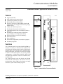
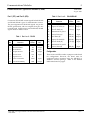
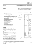
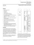
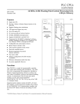
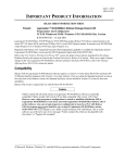
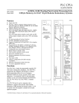
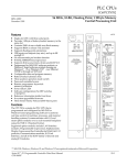
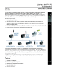
This Datasheet for the
IC697CMM711
Communications Coprocessor, CCM, RTU, SNP, and SNPx Protocols.
http://www.qualitrol.com/shop/p-14774-ic697cmm711.aspx
Provides the wiring diagrams and installation guidelines for this GE Series 90-30
module.
For further information, please contact Qualitrol Technical Support at
1-800-784-9385
[email protected]
1
Communications Modules
IC697CMM711
71
GFK-0370F
August 1997
Communications Coprocessor Module (CMM)
Communications Coprocessor Module (CMM) (IC697CMM711)
datasheet GFK-0370F
Features
D
D
D
D
D
D
D
D
D
D
D
D
D
D
Single-Slot Module
SNP/SNP-X Protocol (master, slave)
CCM Protocol (master, slave, peer)
RTU Modbus Protocol (slave only)
Supports connection to MS-DOSr or Windowsr
programming and configuration software package
(monitor only)
12 Mhz, 80C186 Microprocessor
Two RS-422/RS-485 or RS-232 Serial Ports
CCM, RTU and SNP/SNP-X Available on Either or
Both Ports
Simultaneous Communications on Both Ports
(up to 9.6 Kbps, or 19.2 Kbps individually)
High Performance Access to PLC Memory
Three Status LEDs
Reset pushbutton
Soft Switch Configuration (no switches or jumpers)
No Battery Required
a44823
OK
PORT 1
PORT 2
COMMUNICATIONS
COPROCESSOR
ÎÎ
Î
ÎÎÎÎÎ
ÎÎÎ
Î
Î
ÎÎ
ÎÎ
ÎÎÎ
ÎÎ
Î
ÎÎ
Î
Î
Î
Î
Î
Î
Î
Î
Î
Î
Î
Î
Î
Î
Î
Î
Î
Î
Î
Î
Î
CMM 711
MODULE OK
PORT 1
PORT 2
ON = OK, ACTIVE
BLINK =
COMMUNICATING
PUSH TO RESTART
APPLICATION
PORT 1
RS–232 OR
RS–422
COMPATIBLE
PORT 2
RS–232 OR
RS–422
COMPATIBLE
MODULE FUNCTION
Functions
COMMUNICA TIONS
COPROCESSOR
PORT 1 & 2 RS–232
PIN
SIGNAL
The Communications Coprocessor Module (CMM) is a
member of a family of communication modules, and
provides both communications control (CCM), remote
terminal (RTU), and general IC69* communications
(SNP) functionality. CCM, RTU and SNP are available
on either or both serial ports in any of nine possible
configurations: CCM/CCM, CCM/RTU, RTU/CCM,
RTU/RTU,SNP/SNP,SNP/CCM,CCM/SNP,SNP/RTU,
and RTU/SNP
.
1
SHIELD
2
TD
3
4
RD
RTS
5
7
CTS
GROUND
DCD *
*
DTR
8
20
PORT 1 & 2 RS–422
PIN
SIGNAL
7
GROUND
9
10
SD (A)
RTS (A)
11
12
*
CTS (A) *
TERM PIN 11
13
21
RD (A)
SD (B)
22
RTS (B)
23
24
25
The CMM provides both the RS-232 and RS-485
Interfaces and communicates with the PLC CPU over
the backplane. Many CMMs can be placed in a single
IC697 PLC system as illustrated by Figure 2.
*
*
*
CTS (B)
TERM PIN 25
*
*
RD (B)
CONFIGURA TION
DEPENDENT
MODULE IC697CMM711
LABEL 44A726758–124R01
Figure 1. Communications Coprocessor Module
r MS-DOS and Windows are registered trademarks of Microsoft Corporation.
t
Series 90 -70 Programmable Controller Data Sheet Manual
GFK-0600F
71-1
Communications Modules
2
GFK-0370F
August 1997
Communications Coprocessor Module (CMM)
CCM:
SNP/SNP-X:
Functions provided by the CMM module in the CCM
mode of operation are: read/write of register, input and
output tables (PLC memory types %R, %I and %Q); bit
set/clear of inputs and outputs (%I and %Q); read of
scratch pad; Q sequence commands for fast reads; and
the ability to modify the diagnostic status word.
SNP is the native protocol of all IC69* PLCs. SNP is a
master-slave protocol, where the slave device responds
to requests from the master. An SNP slave device is built
into every IC69* PLC. Each serial port on the CMM can
be configured to provide SNP master or slave capability.
In the master and peer CCM configurations, the CMM
module initiates communications with remote devices
through application ladder program communications
requests (COMREQs).
RTU:
The RTU mode of operation is a query/response
protocol used for communicating between the CMM
and a host computer. The host computer is the master
device and transmits the query to the RTU slave which
responds to the master. In RTU mode, only slave
configuration is available.
In the RTU slave protocol, the following functions are
provided: read input and output tables (%I and %Q),
read analog input (%AI), read register table (%R), read
scratchpad, read exception status, force a single or
multiple output(s) (%Q), preset a single or multiple
register(s) (%R), report the device type, and perform
loopback maintenance.
71-2
The SNP protocol on the CMM module provides read
and write access to PLC memory (types %R, %I, %Q,
%AI, %AQ, %T, %M, %P, %L, and %G), full Series 90
Datagram support, and many status and control
functions. An Autodial feature is also provided to
control a modem attached to an SNP master port.
The SNP-X extensions to SNP provide easy-to-use, high
performance read and write access to PLC memory
(types %R, %I, %Q, %AI, %AQ, %T, %M, and %G).
SNP-X is especially useful for simple, high-speed data
acquisition and control in multidrop configurations.
As an SNP master, the CMM module initiates
communications with remote devices through
application ladder programs communication requests
(COMREQS). An SNP master port on a CMM module
can communicate with the SNP slave port built into any
IC69* PLC, or with other SNP slave devices.
As an SNP slave, the CMM module provides additional
communications port(s) for connection to remote
operator interface units or other SNP communications
devices. The MS-DOS or Windows based software
package may be connected to an SNP slave port on a
CMM module for data monitoring only. Programming
and configuration of IC69* PLCs are not possible
through the CMM SNP ports.
t
Series 90 -70 Programmable Controller Data Sheet Manual
GFK-0600F
Communications Modules
3
GFK-0370F
August 1997
Communications Coprocessor Module (CMM)
Systems Configuration
Figure 2 illustrates typical CMM interface installations in a IC69* PLC system.
a45299
PARALLEL
ÎÎÎÎ
Î ÎÎÎÎ
ÎÎÎÎÎÎ
ÎÎÎÎÎÎÎÎ
Î
Î
ÎÎÎÎÎÎÎÎ
IC697 PLC (RACK 0)
Î
P
S
C B C C
P T M M
U M M M
G
B
C
ONE
METER
PROGRAMMER
(GENERIC) PC
IC697 PLC (RACK 1)
B
R
M
Î
C
M
M
Î
(GENERIC) PC
MASTER
CCM
DEVICE
PEER
CCM
DEVICE
ÎÎÎÎÎÎÎÎÎ
ÎÎÎÎÎÎÎÎ
ÎÎÎÎÎÎÎÎÎ
ÎÎÎÎÎÎÎÎ
ÎÎÎÎÎÎÎÎÎ ÎÎÎÎÎÎÎÎ
(GENERIC) PC
IC697 PLC (RACK 6)
NOTE
Î
Î
B C
R M
M M
ALL RACKS MUST
BE AT SAME
GROUND POTENTIAL
(8 RACKS MAXIMUM).
SNP SLAVE DEVICES
MASTER
RTU
DEVICE
ÎÎÎÎÎÎÎÎ
ÎÎÎÎÎÎÎÎ
ÎÎ
Î
ÎÎ
Î
ÎÎ
Î
Î
ÎÎ
Î
ÎÎ
Î
ÎÎ
ÎÎÎÎÎ
ÎÎÎ
ÎÎ
ÎÎ
ÎÎÎÎÎ
Î
Î
Î
ÎÎ
Î
ÎÎ
Î
ÎÎ
ÎÎ
Î
ÎÎ
ÎÎÎ
ÎÎÎÎ
ÎÎ
ÎÎÎ
ÎÎÎ
Î ÎÎÎÎÎ
ÎÎ Î
C
P
U
ONE
METER
C
M
M
P
S
IC697 PLC
C B C
P T M
U M M
IC693 PLC
IC692 PLC
IC697 PLC (RACK 7)
Î
P
S
B
R
M
Î
I/O TERMINATOR (LAST RACK)
Î
LEGEND
CPU
BRM
BTM
GBC
CMM
PS
–
–
–
–
–
–
SELECTED CPU MODEL
BUS RECEIVER MODEL, BEM711
BUS TRANSMITTER MODEL, BEM713
GENIUS BUS CONTROLLER, BEM731
COMMUNICATIONS COPROCESSOR MODULE
POWER SUPPLY, PWR710/711/724/748
Figure 2. Typical PLC System Configuration
t
Series 90 -70 Programmable Controller Data Sheet Manual
GFK-0600F
71-3
Communications Modules
4
GFK-0370F
August 1997
Communications Coprocessor Module (CMM)
Module Physical Description
User Maintenance Items
The CMM module is a single-slot module that plugs into
either the IC697 PLC or I/O rack.
The CMM module has the following user-accessible
elements:
Figure 3 shows the maintenance controls and indicators
located on the CMM module.
D Three LEDs located at the top of the module.
D Restart Pushbutton: located immediately beneath
the LEDs.
D Two Serial Ports: two 25-pin female connectors proa44825
vide RS-232 and RS-422/RS-485 communication.
Installation
ÎÎ
ÎÎ
Installation should not be attempted without referring
to the Installation Manual. (See Related Publications
listed on page 6.)
D Make sure rack power is OFF before attempting to
Î
Î
Î Î
CMM 711
MODULE OK
PORT 1
PORT 2
ON = OK, ACTIVE
BLINK =
COMMUNICATING
PUSH TO RESTART
APPLICATION
PORT 1
RS–232 OR
RS–422
COMPATIBLE
PORT 2
RS–232 OR
RS–422
COMPATIBLE
MODULE FUNCTION
COMMUNICA TIONS
COPROCESSOR
PORT
PIN
1
2
3
4
5
7
8
20
1 & 2 RS–232
SIGNAL
SHIELD
TD
RD
RTS
CTS
GROUND
DCD
*
DTR
*
PORT 1 & 2 RS–422
PIN SIGNAL
7
9
10
11
12
13
21
22
23
24
25
*
GROUND
SD (A)
RTS*(A)
CTS*(A)
TERM*PIN 11
RD (A)
SD (B)
RTS*(B)
CTS* (B)
TERM *PIN 25
RD (B)
CONFIGURA TION
DEPENDENT
install module.
D Install module in the rack (see Figure 2).
D Turn ON power.
The CMM is configurable only using the MS-DOS or
Windows programming software package.
Status Indication
Three Status LEDs are available as shown in Figure 3.
The top LED indicates the condition of the module. The
bottom two LEDs indicate activity at the serial ports:
Port 1 LED indicates activity on port 1; Port 2 LED
indicates activity on port 2.
The module should power up and blink the top LED.
When the diagnostics have completed successfully, the
top LED stays on.
Pushbutton Control
One pushbutton is provided. Push to reinitialize
communications at both serial ports.
Serial Ports
MODULE IC697CMM711
LABEL 44A726758–124R01
CMM 711
Both ports are RS-232 and RS-422/RS-485 compatible.
Both ports acting simultaneously can each provide up
to 9.6 Kbps of full duplex data communications, or up to
19.2 Kbps individually.
Figure 3. CMM Module - User Details
71-4
t
Series 90 -70 Programmable Controller Data Sheet Manual
GFK-0600F
Communications Modules
5
GFK-0370F
August 1997
Communications Coprocessor Module (CMM)
Table 2. Port 1 or 2:
Port 1 (3PL) and Port 2 (4PL):
Connectors 3PL and 4PL contain signals for both RS-232
and RS-422/RS-485 types of communication circuits.
The pin assignment for the RS-232 signals are per the
RS-232 specification with an exception that pins not
normally used for RS-232 are used for RS-422/RS-485
signals. Refer to Tables 1 and 2.
Table 1. Port 1 or 2: RS-232
Pin
Function
Signal
Name
I/O
-
-
1
Shield
2
Transmitted Data
TD
Output
3
Received Data
RD
Input
4
Request To Send
RTS
Output
5
Clear To Send
CTS
Input
7
Signal Ground
0V
-
8
Data Carrier Detect
DCD
Input
20
Data Terminal Ready
DTR
Output
t
Series 90 -70 Programmable Controller Data Sheet Manual
GFK-0600F
Pin
Function
RS-422/RS-485
Signal
Name
I/O
9
Send Data (A)
SD (A)
Output
10
Request To Send (A)
RTS (A)
Output
11
Clear To Send (A)
CTS (A)
Input
12
Termination for pin 11
-
-
13
Receive Data (A)
RD (A)
Input
21
Send Data (B)
SD (B)
Output
22
Request To Send (B)
RTS (B)
Output
23
Clear To Send (B)
CTS (B)
Input
24
Termination for pin 25
-
-
25
Receive Data (B)
RD (B)
Input
Configuration
There are no user DIP switches or jumpers on this board
for configuration. However, the board must be
configured before operation using the MS-DOS or
Windows software package. Refer to the Related
Publications listed on page 6.
71-5
Communications Modules
6
GFK-0370F
August 1997
Communications Coprocessor Module (CMM)
Table 3. Related Publications
Reference
1
2
3
4
5
Title
ProgrammingSoftware User ’s Manual
Programmable Controller Reference Manual
Programmable Controller Installation Manual
PLC Serial Communications User ’s Manual
Using the Windows Programmer (GFK-1295)
Table 4. Module Specifications [
Current Required from +5V backplane bus
RS-232 and RS-422/RS-485 compatible
0.7 amps
VME
System designed to support the VME standard C.1
Serial Ports
[ Refer to GFK-0867B, or later for product standards and general specifications. Forinstallations
requiring compliance to more stringent requirements (for example, European Union), refer to Installation
requirements for Conformance to Standards.
Table 5. Ordering Information
Description
Catalog Number
Communications Coprocessor Module (CMM)
IC697CMM711
Note: For Conformal Coat option, or Low Temperature Testing option please consult the
factory for price and availability.
71-6
t
Series 90 -70 Programmable Controller Data Sheet Manual
GFK-0600F