1
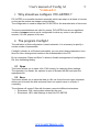
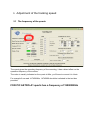
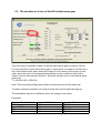
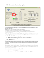
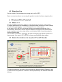
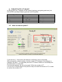
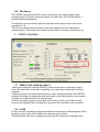
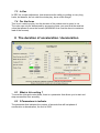
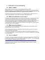
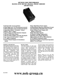
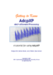
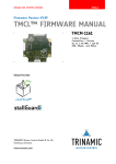
User's manual of Config A1
Version 1.1
www.astrimage.org
1
User's manual of Config A1
Version 1.1
2
Summary
1 Why should we configure PIC-ASTRO ?...............................................................................3
2 The program ConfigA1............................................................................................................3
2.1 Open..................................................................................................................................3
2.2 Save...................................................................................................................................3
3 Adjustment of the tracking speed.............................................................................................4
...............................................................................................................................................4
3.1 The frequency of the quartz..............................................................................................4
3.2 The duration of a turn of the RA helical worm gear.........................................................5
3.3 The number of microsteps by turn....................................................................................6
4 Adjustments for periodic error correction................................................................................6
4.1 PEC-1 slices .....................................................................................................................6
4.2 Steps by slice ....................................................................................................................7
5 Choose of the IT period...........................................................................................................7
5.1 What's IT ?........................................................................................................................7
5.2 Select the duration of a couple of IT and IT Number.......................................................7
6 Adjustments of speed...............................................................................................................9
6.1 How to choose speed ?......................................................................................................9
6.2 What are the value of the speed in RA?..........................................................................10
6.2.1 Tracking...................................................................................................................10
6.2.2 Autoguiding.............................................................................................................10
6.2.3 Maximum.................................................................................................................10
6.3 In declination...................................................................................................................10
6.3.1 Tracking...................................................................................................................10
6.3.2 Autoguiding.............................................................................................................10
6.3.3 Maximum.................................................................................................................10
6.4 The focus.........................................................................................................................11
7 Catch up plays........................................................................................................................11
7.1 What is the catch-up plays? ...........................................................................................11
7.2 In RA...............................................................................................................................11
7.3 In Dec..............................................................................................................................12
7.4 For the focus....................................................................................................................12
8 The duration of acceleration / deceleration............................................................................12
8.1 What is this setting ?.......................................................................................................12
8.2 2 Parameters to indicate..................................................................................................12
9 Calibration of microstepping.................................................................................................13
9.1 What's a PWM ?..............................................................................................................13
9.2 What's the calibration of microsteps ?............................................................................13
9.3 When we must calibrate ?...............................................................................................13
9.4 How to calibrate?............................................................................................................13
www.astrimage.org
User's manual of Config A1
Version 1.1
1
3
Why should we configure PIC-ASTRO ?
PIC-ASTRO is a versatile electronic assembly which can adapt to all kinds of mounts,
as long as the motors are stepper motors bipolar.
The configuration is used to adapt the PIC-ASTRO to the characteristics of its mount.
The same considerations are valid for motors, PIC-ASTRO can drive a significant
number of stepper motors and is configurable to drive any motor in an optimum
manner, if it's the purpose of its user.
2
The program ConfigA1
The realization of this configuration is semi-automatic, it is necessary to specify a
certain number of parameters.
ConfigA1 software is a Windows executable, you can enter these parameters, save
them for future changes and creates a file downloadable to the PIC.
By its commands "Open and Save" it allows a flexible management of configuration
file, thus facilitating testing.
2.1 Open
This button allows you to open a file .PA2 existing, for changing these settings.
The operation is a classic, an explorer is open to browse the disk and open the
appropriate file.
2.2 Save
This button allows you to save the data in a file, as for the function open a browser
allows you to browse the disk and save files in an explicit name in a folder, if
necessary.
The software will create 2 files with the same name but different extensions:
• Extensions. PA2: storing data entered by the user
• Extensions. HEX: table settings to load into PIC-ASTRO
www.astrimage.org
3
Adjustment of the tracking speed
3.1 The frequency of the quartz
The quartz gives the operating frequency of the mounting, it has a direct effect on the
operation frequency of the motors.
The value is usually indicated on the quartz in Mhz, you'll have to convert it in Hertz.
For example if we read 14.7456MHz, 14745600 should be indicated in the text box
provided.
FOR PIC ASTRO-A1 quartz has a frequency of 15000000Hz
3.2 The duration of a turn of the RA helical worm gear
This is the time in seconds it takes for the RA helical worm gear to make a full turn.
For mounts with a couple helical worm gear / crown wheel, we need to find time for a
turn of the helical worm gear, divide the length of a full rotation of the mount (or the
earth, since the aim is to compensate this rotation) by the number of teeth of the
wheel. A mount built around a wheel of 180 teeth, will give a turn of the helical worm
gear every :
T = 86164.4/180 = 478.691s
Note: This is the sidereal day that is taken as reference and not the solar day.
To obtain maximum precision, we must give the value with 6 significant figures.
The declination may have a different value, the setting is done later.
Examples:
Mount
CI700
Vixen SP/GP
EQ5
EQ6
Teeth
180
140
144
180
Period
478.691
615.46
598.3639
478.691
3.3 The number of microsteps by turn
The number of micro-step that PIC-ASTRO shall generate for the helical worm gear
to make a full turn.
Attention, PIC-ASTRO uses 16 micro-step by step.
To find the number of micro-step, use the following relationship:
N = Number of microsteps by steps × Number of steps per revolution motor ×
reduction ratio used
In the case of a mount driven by a 400 steps motor by turn, and a transmission pulley
1:3 (small pulley on the motor of 16 tooth, and large pulley on the helical worm gear
of 48 teeth) will :
N = 16 × 400 × 3 = 19200 microsteps by turn
4
Adjustments for periodic error correction
4.1 PEC-1 slices
The PEC is treated by cutting a turn of the helical worm gear into a number of slices
(1 to 256). This means that the correction is determined to change the motor speed
for a slice.
Warning: this means that the number of slices X number of steps by slice = the exact
number of steps per revolution. It must therefore be wary of bizarre gear that will not
allow to have a correct PEC.
It is a value which must be between 0 and 255 :
•
•
0 for non-use of the PEC 0
otherwise the number of slices -1: 255 means 256 units of PEC
4.2 Steps by slice
It's the number of microsteps done during a slice of the PEC.
Same comment as above concerning the product number of slices x steps by slice.
5
Choose of the IT period
5.1 What's IT ?
A small simplified explanation helps to understand the importance of this setting.
IT means interruption it is a possibility of microcontrollers, which at an event (receipt
of a character, hit a button, ...) can be stopped to run a sub program.
In the case of PIC-ASTRO, an internal counter increments automatically, like a
chronometer, and when a certain value is reached, the program will command the
motor to advance of a micro-step, before continuing to where it was interrupted to
continue its execution.
You can also count the IT and trigger the next microsteps only after a number of IT
has occurred. It is used in PIC-ASTRO to have more flexibility when setting.
5.2 Select the duration of a couple of IT and IT Number
To make the selection you had to have informed the previous parts (Chapters 2 and
3), and click on the green box to see the values proposed by the software and make
choices.
the choice of the period of IT is not critical, all
combinations proposed are acceptable, you must have one
or more selection criteria. These criteria can be
summarized as follows:
1. The More the period is large the more PICASTRO will respond quickly to orders
received
2. With the linearized μsteps a good time must
be less than or equal to 2000000ns with a
number of more than 10 IT
3. The error rate is not significant with
autoguiding
4. The max speed is the final criterion to be
taken into account, it is more subjective
In the list that appears, you can read in order :
o IT period in nanoseconds, the value will go down in the green box
o the error is a rate, for a percentage, multiply the value by 100
o the value loaded into the internal pic
o the number of IT, which will take place during a microstep. The maximum
theoretical speed that can be obtained in the form X times the sidereal rate
(Vmax = 8 x number of IT).
If the right ascension and declination have different gear ratios, it is necessary to
monitor the number of IT being able to adjust later. It's a bit clever, but very flexible.
An example, if the DEC is multiplied twice as RA, the number of IT DEC will be two
times smaller, which will advance the "double" speed motor , ie has the same speed
of the RA motor.
Against it is imperative to maintain the entire agreement between RA and DEC, but
mathematicians can also juggle with fractions.
6
Adjustments of speed
In RA and Dec only 3 speeds can be entered (tracking, autoguiding and max), but
PIC-ASTRO use these datas to generate until 63 speeds :
Speed
0
1
2
3à7
8 à 63
Value
0
Tracking
Autoguiding
from 3X to 7X
from 8X to Max
mode
microsteps
microsteps
microsteps
halfsteps
6.1 How to choose speed ?
If you tick box 1 / 2 the motor will advance in half-step, if not in microstep.
We must specify a whole number, it is the number of IT between 2 microsteps (or
halfstep if the box 1 / 2 is checked), the more IT is small, smaller is a microstep and
thus the motor is running fast.
For technical reasons, we can not exceed 128 for the number of IT.
If it is a limit, it should return to the previous step, increase the duration of IT, in order
to reduce the number of IT.
6.2 What are the value of the speed in RA?
6.2.1 Tracking
The tracking speed is the sidereal speed which is activate for tracking, the value and
isn't adjustable. This speed must be in microstep.
6.2.2 Autoguiding
The autoguiding speed is the correction speed during autoguiding commands.For a
first try, we recommand 1,5×. This speed must be in microstep.
6.2.3 Maximum
The Maximum speed : you shall be ensured that the motors can actually move at
this speed, depending on their power, the ratio, their frequency limit in steps per
second, and the load weight of the mount. When a stepping motor can not follow, he
stopped and vibrates in a serious buzzer noise characteristic. This speed must be
in halfstep.
6.3 In declination
6.3.1 Tracking
The tracking speed is not used, there is no tracking in DE, but it allows PIC-ASTRO
to know the relationship between multiplication RA and Dec.
If the right ascension and declination are identical (same overall ratio), the values are
the same in Dec in RA.
But if the gear ratios are different, the values will be different.
In the case of a mount with a Dec 3 times more demultipliate than the RA, the
declination tracking value will be the 1 / 3 of the tracking value of the RA.
It must check that the value chosen for the number of IT is a multiple of gear ratio.
6.3.2 Autoguiding
Attention, The declination speed will be different, for 1.5× in RA, you'll put 0.5× in
Dec !
The reason is that in RA, the speed is V(RA)=(1.0±0.5)X while in DEC it's
V(DEC)=(0,0±0.5)X
6.3.3 Maximum
The Maximum speed : you shall be ensured that the motors can actually move at
this speed, depending on their power, the ratio, their frequency limit in steps per
second, and the load weight of the mount. When a stepping motor can not follow, he
stopped and vibrates in a serious buzzer noise characteristic. This speed must be
in halfstep.
6.4 The focus
PIC-ASTRO can command a DC motor for focusing, you may indicate a slow
tracking speed (1X) and a maximum speed. For this motor PIC-ASTRO define 7
speeds uniformly distributed.
To adjust this you should first adjust the duration of the pulses sent to the motor
(paragraph 7.4).
Then by successive tests to determine the slow speed (from 255 and then by
reducing them). Then adjust the speed (from the value 1 and then increasing it in).
7
Catch up plays
7.1 What is the catch-up plays?
When gear stops then change direction, it takes some time for the teeth to go to
reach the other side. In the case of guiding, it is a dead time during which nothing
happens.
Catching up play for shortening this time out, when changing direction PIC-ASTRO
performs a number of steps to go stick their teeth in the other direction, this number
of steps has to be indicate in his configuration.
Attention should be given for the margin and not try to catch up the play entirely,
because the slightest fault, catching up is going too far, and that's over-correction.
7.2 In RA
IN RA, we have a catching up plays that allows to don't have to wait that gears sticks
together in goto mode, this enable to be centered on the object.
The adjustment isn't used in guiding, because the RA motor never change sense.
7.3 In Dec
In DEC it's a major adjustment, that determines the ability to guiding on very long
hauls, but beware, do not catch the whole play, leave a little margin.
7.4 For the focus
This is not a catch-up play, but the duration of the pulses sent to motor in ms.
The value can only be determined by successive tests: you must find the smallest
value that allows to move the focuser (WARNING: this must be done to maximum
load of the focuser).
8 The duration of acceleration / deceleration
8.1 What is this setting ?
To avoid the jolts and motor slides, there is a parameter that allows you to start and
stop movements Goto smoothly.
8.2 2 Parameters to indicate
The parameter that indicates the number of seconds that will last phase of
acceleration or deceleration, the limit is 256S.
9
Calibration of microstepping
9.1 What's a PWM ?
When a bulb is lit continuously, it can be said that it shines 100%
Imagine that you lit it 1s, and then extinguish it for 1s, and so on, it will work half the
time. If one performs these operations on a very short time, it no longer sees the time
of ignition and extinction, but we will see a light bulb shining at 50%.
One can, by varying the time switched on / off, make all states of light from 0% to
100%, is the principle of pulse width modulation PWM abbreviated.
9.2 What's the calibration of microsteps ?
A stepper motor advance step by step, from a self to the next, it's pretty brutal. What
we can do to improve this behavior is to switch on a self slowly while gradually
switched off the previous one, the change of position is milder, and we can even cut
the space between two steps 16 intermediate positions called microstep. For a
couple Motor/ PIC-ASTRO, we talk about calibration when adjusts the PWM to have
the same width for all microsteps.
9.3 When we must calibrate ?
The calibration muste be made for every new configuration of motorisation, and
electronical part too so PIC-ASTRO.
Pulley transmissions have the advantage of smoothing the error period, because I
think the elasticity of the pulley.
The problem is the gear ratio is quite low, a step of the motor is correspond to few
arc seconds on the sky, to make moving fluid it is essential to calibrate the micro-step
of its PIC-ASTRO.
9.4 How to calibrate?
A friendly and simple method was developed to perform the calibration of PWM. This
method uses software on PCs and software specific PIC-ASTRO. You can download
all the necessary elements using the following link:
http://astrimage.org/FTP/Public/pic-astro/documentations/ReglagePWMV3.zip
This document was created by Vincent STEINMETZ and formatted by Arnaud
GERARD for Astrimage.