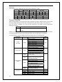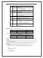
1
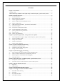
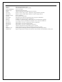
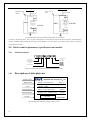
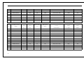
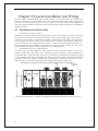
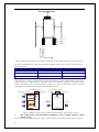
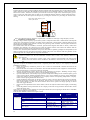
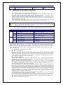
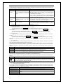
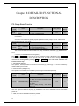
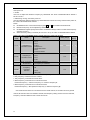
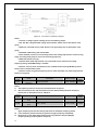
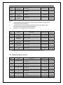
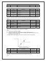
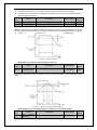
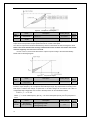
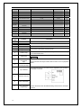
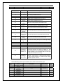
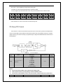
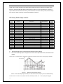
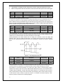
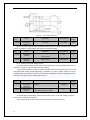
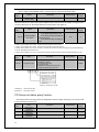
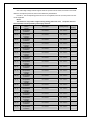
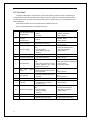
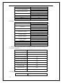
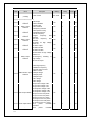
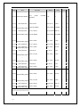
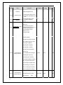
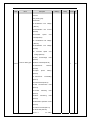
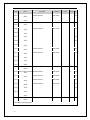
Grounding connection Firm, with good conduction Inspect by wrenching and guiding 4.2 Installation of the high voltage parts 1. Standard requirement of high voltage distributions Firstly, the high voltage power supply needs to pass through the main circuit breaker and then shall be connected to CHH Series high voltage variable frequency speed control systems; it is allowed to close the main circuit breaker only after receiving the high voltage closing permit signal. The high voltage power supply of the main circuit breaker shall be directly connected into the input terminal of the switch cabinets (or incoming cabinets) of the variable frequency speed control system without the need of passing through the input reactor. The variable frequency output of high voltage variable frequency speed control systems is directly connected to high voltage motors via the output terminals of the switch cabinets (or incoming cabinets). Notes 2. The input and output terminals cannot be connected incorrectly, otherwise the high voltage variable frequency speed control systems will be damaged. Wiring of the switch cabinets of high voltage variable frequency speed control systems Terminal ID Input L1 L2 L3 Output U V W Terminal name Main circuit power supply input, 1st phase sequence Main circuit power supply input, 2nd phase sequence Main circuit power supply input, 3rd phase sequence High voltage frequency inverter output, 1st phase sequence High voltage frequency inverter output, 2nd phase sequence High voltage frequency inverter output, 3rd phase sequence Remarks Connect to 3-phase high voltage AC power supply, 1st phase sequence Connect to 3-phase high voltage AC power supply, 2nd phase sequence Connect to 3-phase high voltage AC power supply, 3rd phase sequence Connect to 3-phase AC high voltage motor, 1st phase sequence Connect to 3-phase AC high voltage motor, 2nd phase sequence Connect to 3-phase AC high voltage motor, 3rd phase sequence 【Remarks】The phase sequence of U, V and W output of the high voltage variable frequency speed control systems may be inconsistent with the phase sequence of power supply L1, L2 and L3; on the occasions when the power frequency power supply bypass is needed, please check the I/O phase sequences of the high voltage variable frequency speed control systems, and make the phase sequence of both consistent, otherwise the system may not work normally. 3. Requirements of equipment and cables Main circuit breaker The main circuit breaker may be the vacuum or gas insulation circuit breaker. It must not only meet the requirement of the supply voltage and current, but also the requirement of the rated voltage and current of the trans-phase transformer on the primary side. Its basic electrical characteristic also has to be able to bear the closing impulse current of the transformer and the failure current caused by the secondary side short circuit of the transformer within 100ms, and won’t cause trip. Protective equipment The high voltage switch on the power side of CHH Series high voltage variable frequency speed control systems shall be configured with reasonable protection, the setting of the protection definite value shall be carried out in reference to the following principles: When the winding on the primary side or the incoming cables on the primary side of the trans-phase transformer fails, the switch must conduct immediate trip. The setting value of the protection current must be sure to dodge the excitation surge current for switching-in no-load without trip (this can be set as 8 to 10 times of the rated current of the trans-phase transformer). The fault protection of the secondary side of trans-phase transformers adopts the method of delayed trip. When short circuit failure occurs to the winding on the secondary side of the trans-phase transformer, the cables connecting the secondary side of the trans-phase transformer with system units, and the unit input bridge rectifier, the incoming switch can be flipped open. With short delay of protection, the time settings can be adjusted and can be set to ensure the trans-phase transformer of no trip will occur during the period of excitation surge current. The movement current setting value can be set as twice the rated current of the rectifying transformer, so as to ensure that when failure occurs on the secondary side of the rectifying transformer, trip will be performed within 500ms. Overload protection (optional) is a long-time overload protection with the feature of inverse time limit, and can protect the long-time overload of transformers and cables. If the system is a part of a high-voltage large-capacity motor reconstruction project, the vertical protection of the high voltage motor protection shall quit during the variable frequency operation, and shall be put in during the power frequency bypass, the switching function needs to be realized in the technical schemes. Primary side cables of transformers 25