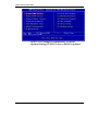
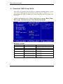
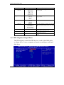
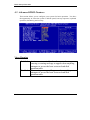
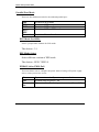
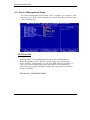
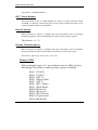
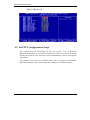
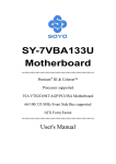
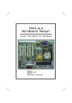
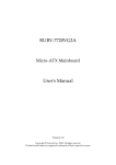
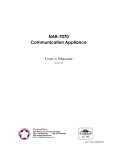
1
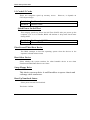
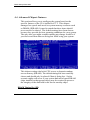
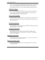
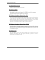
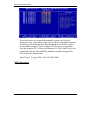
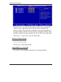
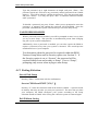
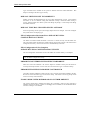
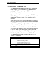
BIOS Setup Information CHAPTER 4 BIOS Setup Information ROBO-667 is equipped with the AWARD BIOS stored in Flash ROM. This BIOS has a built-in Setup program that allows users to modify the basic system configuration easily. This type of information is stored in CMOS RAM so that it can be retained during power-off periods. When system is turned on, ROBO-667 communicates with peripheral devices and check its hardware resources against the configuration information stored in the CMOS memory. If any error is detected, or the CMOS parameters need to be initially defined, the diagnostic program will prompt the user to enter the SETUP program. Some errors are significant enough to abort the start-up. 4.1 Entering Setup Turn on or reboot the computer. When the message “Hit <DEL> if you want to run SETUP” appears, press <Del> key immediately to enter BIOS setup program. If the message disappears before you respond, but you still wish to enter Setup, please restart the system to try “COLD START” again by turning it OFF and then ON, or touch the "RESET" button. You may also restart from “WARM START” by pressing <Ctrl>, <Alt>, and <Delete> keys simultaneously. If you do not press the keys at the right time and the system will not boot up, an error message will be displayed and you will again be asked to, Press <F1> to Run SETUP or Resume In HIFLEX BIOS setup, you can use the keyboard to choose among options or modify the system parameters to match the options with your system. The table below will show you all of keystroke functions in BIOS setup. ROBO-667 User’s Manual 4-1 BIOS Setup Information Keys to navigate within setup menu Key Functions Up Arrow Down Arrow Left Arrow Right Arrow Move Enter PgUp key PgDn key + key - key Esc key Move to the previous item Move to the next item Move to the item on the left (menu bar) Move to the item on the right (menu bar) Move to the item you desired Increase the numeric value or make changes Decrease the numeric value or make changes Increase the numeric value or make changes Decrease the numeric value or make changes Main Menu -- Quit and not save changes into CMOS Status Page Setup Menu and Option Page Setup Menu -- Exit current page and return to Main Menu General help on Setup navigation keys Load previous values from CMOS Load the fail-safe defaults from BIOS default table Load the optimized defaults Save all the CMOS changes and exit F1 key F5 key F6 key F7 key F10 key 4.2 Main Menu Once you enter ROBO-667 AWARD BIOS CMOS Setup Utility, you should start with the Main Menu. The Main Menu allows you to select from eleven setup functions and two exit choices. Use arrow keys to switch among items and press <Enter> key to accept or bring up the sub-menu. ROBO-667 User’s Manual 4-2 BIOS Setup Information NOTE : It is strongly recommended to reload Optimal Setting if CMOS is lost or BIOS is updated. ROBO-667 User’s Manual 4-3 BIOS Setup Information 4.3 Standard CMOS Setup Menu This setup page includes all the items in a standard compatible BIOS. Use the arrow keys to highlight the item and then use the <PgUp>/<PgDn> or <+>/<-> keys to select the value or number you want in each item and press <Enter> key to certify it. Follow command keys in CMOS Setup table to change Date, Time, Drive type, and Boot Sector Virus Protection Status. Menu seletions Item Options Description Date Mm:dd:yy Time IDE Primary Master Hh:mm:ss Options are in its sub menu (described in 4.4 Table) Options are in its sub menu (described in 4.4 Table) Options are in its sub menu (described in 4.4 Table) Options are in its sub menu (described in 4.4 Table) Set the system date. Note that the ‘Day’ automatically changes when you set the date Set the system time Press <Enter> to enter the sub menu of detailed options Press <Enter> to enter the sub menu of detailed options Press <Enter> to enter the sub menu of detailed options Press <Enter> to enter the sub menu of detailed options IDE Primary Slave IDE Secondary Master IDE Secondary Slave ROBO-667 User’s Manual 4-4 BIOS Setup Information Item Options Description Drive A Drive B Select the type of floppy disk drive installed in your system Base Memory None 360K, 5.25 in 1.2M, 5.25 in 720K, 3.5 in 1.44M, 3.5 in 2.88M, 3.5 in Disabled Drive A Drive B Both EGA/VGA CGA 40 CGA 80 MONO All Errors No Errors All, but Keyboard All, but Diskette All, but Disk/Key N/A Extended Memory N/A Total Memory N/A Floppy 3 Mode Support Video Halt On Select which drive you would like to set to floppy 3 mode. Select the default video device Select the situation in which you want the BIOS to stop the POST process and notify you Displays the amount of conventional memory detected during boot up Displays the amount of extended memory detected during boot up Displays the total memory available in the system 4.4 IDE Adaptors Setup Menu The IDE adapters control the IDE devices, such as hard disk drive or cdrom drive. It uses a separate sub menu to configure each hard disk drive. ROBO-667 User’s Manual 4-5 BIOS Setup Information Menu seletions Item Options Description IDE HDD Autodetection Press Enter IDE Primary Master None Auto Manual Access Mode CHS LBA Large Auto Auto Display your disk drive size Press Enter to auto-detect the HDD on this channel. If detection is successful, it fills the remaining fields on this menu. Selecting ‘manual’ lets you set the remaining fields on this screen. Selects the type of fixed disk. "User Type" will let you select the number of cylinders, heads, etc. Note: PRECOMP=65535 means NONE ! Choose the access mode for this hard disk Capacity Disk drive capacity (Approximated). Note that this size is usually slightly greater than the size of a formatted disk given by a disk checking program. The following options are selectable only if the ‘IDE Primary/Secondary Master/Slave’ item is set to ‘Manual’ Cylinder Min = 0 Set the number of cylinders for this hard disk. Max = 65535 Head Min = 0 Set the number of read/write heads Max = 255 Precomp Min = 0 **** Warning: Setting a value of 65535 means no Max = 65535 hard disk Landing zone Min = 0 **** Max = 65535 Sector Min = 0 Number of sectors per track Max = 255 ROBO-667 User’s Manual 4-6 BIOS Setup Information 4.5 Advanced BIOS Features This section allows you to configure your system for basic operation. You have the opportunity to select the system’s default speed, boot-up sequence, keyboard operation, shadowing and security. Virus Warning Enabled Disabled Activates automatically when the system boots up causing a warning message to appear when anything attempts to access the boot sector or hard disk partition table. No warning message will appear when anything attempts to access the boot sector or hard disk partition table. ROBO-667 User’s Manual 4-7 BIOS Setup Information L1 Cache/L2 Cache These two categories speed up memory access. CPU/chipset design. Enabled Disabled However, it depends on Enable cache Disable cache Quick Power On Self Test This category speeds up Power On Self Test (POST) after you power up the computer. If it is set to Enable, BIOS will shorten or skip some check items during POST. Enabled Disabled Enable quick POST Normal POST First/Second/Third Boot Device The BIOS attempts to load the operating system from the devices in the sequence selected in these items. Boot Other Device Select whether the system searches for other bootable device or not when First/Second/Third Boot Device can’t boot. Swap Floppy Drive This choice can swap drive A and B needless to open a chassis and exchange cable connectors. Boot Up NumLock Status Select power on state for NumLock. The choice: Off/On. ROBO-667 User’s Manual 4-8 BIOS Setup Information Security Option Select whether the password is required every time the system boots or only when you enter setup. System Setup The system will not boot and access to Setup will be denied if the correct password is not entered at the prompt. The system will boot, but access to Setup will be denied if the correct password is not entered at the prompt. Note : To disable security, select PASSWORD SETTING at Main Menu and then you will be asked to enter password. Do not type anything and just press <Enter>, it will disable security. Once the security is disabled, the system will boot and you can enter Setup freely. OS Select For DRAM > 64MB Select the operating system that is running with greater than 64MB of RAM on the system. The choice: Non-OS2, OS2. ROBO-667 User’s Manual 4-9 BIOS Setup Information 4.6 Advanced Chipset Features This section allows you to configure the system based on the specific features of the VIA Apollo Pro133T. This chipset manages bus speeds and access to system memory resources such as DRAM (SDRAM). It must be stated that these items should never need to be altered. The default settings have been chosen because they provide the best operating conditions for your system. The only time you might consider making any change would be if you discovered that data was being lost while using your system. This chipset settings deal with CPU access to dynamic random access memory (DRAM). The default timing has been carefully chosen and should only be altered if data is being lost. Such a scenario might well occur if your system had mixed speed DRAM chips installed so that greater delays may be required to preserve the integrity of the data held in the slower memory chips. DRAM Timing By SPD ROBO-667 User’s Manual 4-10 BIOS Setup Information If DIMMs have On-Board Serial Presence Detect (SPD) function, please set it enabled for autodetecting oppotimize DRAM timing. DRAM Clock VIA Apollo Pro133T allows users to adjust DRAM clock by referencing CPU clock (HCLK).There are three modes: HCLK33MHz, HCLK and HCLK+33MHz. SDRAM Cycle Latency This option selects in units of local memory clock periods. The Choice: 2, 3 SCLKs. Bank Interleave There are three modes: disable, 2-way and 4-way. “4-way” has bestest executive performance but needs DIMMs hardware specification support. If not suring DIMMs can support SPD or not, please set this choice at “disable” for maximum stabilty. Memory Hole In order to improve performance, certain space in memory is reserved for ISA cards. This memory must be mapped into the memory space below 16MB. P2C/C2P Concurrency Select the P2C (PCI to CPU) and C2P (CPU to PCI) are synchronized or not. OnChip USB Select for enable/disable on board USB (VT82C686B included). USB Keyboard Support ROBO-667 User’s Manual 4-11 BIOS Setup Information Select for enable/disable USB Keyboard support. Don’t enable this choice when using Microsoft Windows NT 4.0. That will cause system halt because NT does not support USB keyboard function. USB Mouse Support Select for enable/disable USB Mouse support. Don’t enable this choice when using Microsoft Windows NT 4.0. That will cause system halt because NT not support USB. CPU to PCI Write Buffer Enable the choice to open buffer for solving the low performance of data writen form CPU to PCI device.Please enable it if there is not any error occurred PCI Dynamic Bursting When enabling, any data transfer on PCI-BUS will directly transmit without Buffer on VT82C694T. PCI Master 0 WS Write After PCI-Receiver is ready to receive data, PCI-master will immediately send data ( select Enable ) or delay a PCI condition cycle ( select Disable ). PCI Delayed Transaction Select “Enabled” to enable delay transaction.This will enhance performance for data transmission between different PCI bus. Memory Parity/ECC Check System will check DIMMs are 72-bits (support ECC) or 64-bits ( not support ECC). ROBO-667 User’s Manual 4-12 BIOS Setup Information 4.7 Integrated Peripherals ROBO-667 User’s Manual 4-13 BIOS Setup Information OnChip IDE Channel 0/1 Enable or disable on board IDE controller. IDE Prefetch Mode Set enable for the most of cases. If a HDD is too old to support Prefetch Mode, please disable this function. IDE Primary/Secondary Master/Slave PIO The four IDE PIO (Programmed Input/Output) fields let you set a PIO mode (04) for each of the four IDE devices that the onboard IDE interface supports. Modes 0 through 4 provide successively increased performance. In Auto mode, the system automatically determines the best mode for each device. The choice: Auto, Mode 0, Mode 1, Mode 2, Mode 3, Mode 4. IDE Primary/Secondary Master/Slave UDMA Ultra DMA/33/66/100 implementation is possible only if your IDE hard drive supports it and the operating environment includes a DMA driver. If your hard drive and your system software both support Ultra DMA/33/66/100, select Auto to enable BIOS support. Init Display First This item allows you to select the first display port at AGP or PCI to be initialized. ATI M/M1 VGA Chip supports AGP 2X, so please set “AGP” if onboard VGA is needed to be used. ROBO-667 User’s Manual 4-14 BIOS Setup Information IDE HDD Block Mode This item allows you to enable/disable IDE HDD Block Mode. The function is to collect the data that is nearby the one being read and leave them in the system buffer. Buffered data can be used with faster transmission rate so as to enhance system performance. Onboard FDC Controller This item allows you to enable/disable onboard Floppy disk controller. The choice: Enabled/Disabled Onboard Serial Port 1/Port 2 Select an address and corresponding interrupt for the first and second serial ports. The choice: 3F8/IRQ4, 2E8/IRQ3, 3E8/IRQ4, 2F8/IRQ3, Disabled, Auto. UART 2 Mode This item allows users to select Infrared transmission mode. Standard HPSIR ASKIR Disable Infrared function Select IrDA mode transmission Select ASKIR mode transmission As Infrared transmission function shares onboard serial port 2, COM2 needs to be enabled. IR Function Duplex Select Full-Duplex(enable bidirectional data transmission at the same time) or Helf-Duplex(only allow single directional data transmission at the same time) Onboard Parallel Port ROBO-667 User’s Manual 4-15 BIOS Setup Information This item allows you to configure I/O address of the onboard parallel port. The Choices : Disabled, 378/IRQ7, 278/IRQ5, 3BC/IRQ7 ROBO-667 User’s Manual 4-16 BIOS Setup Information Parallel Port Mode There are four different modes for the onboard parallel port : SPP EPP ECP ECP / EPP Normal Switch to SPP mode Switch to EPP mode Switch to ECP mode Switch to ECP or EPP mode Switch to Normal mode ECP Mode Use DMA Select a proper DMA channel for ECP mode. The choices : 3/1 EPP Mode Select Select different version of EPP mode. The choices : EPP1.7/EPP1.9 PWRON After PWR-Fail This item allows user to configure the power status of using ATX power supply after a serious power loss occurs. On Off FormerSts System automatically restores power back System stays at power –off System restores back to previous status (On or Off) ROBO-667 User’s Manual 4-17 BIOS Setup Information 4.8 Power Management Setup The Power Management Setup allows you to configure you system to most effectively save energy while operating in a manner consistent with your own style of computer use. ACPI Function This item allows you to enable/disable the Advanced Configuration and Power Management (ACPI). When AT power supply is the system power source, keeping “ACPI function” at “NO” and “State After Power Failure” at “ON” in the Power Management Setup of the BIOS is recommended. If using ATX power supply, remember to adjust the “State After Power Failure” to proper condition. The choices : Enabled/Disabled. ROBO-667 User’s Manual 4-18 BIOS Setup Information Power Management This category allows you to select the type (or degree) of power saving and is directly related to “HDD Power Down”, “Doze Mode” and “Suspend Mode”. There are three selections for Power Management, three of which have fixed mode settings. Min. Power Saving Max. Power Saving User Defined Minimum power management. Suspend Mode = 1 hr., and HDD Power Down = 15 min. Maximum power management. Suspend Mode = 1 min., and HDD Power Down = 1 min. Allows you to set each mode individually. When not disabled, Suspend Mode ranges from 1 min. to 1 hr. and HDD Power Down ranges from 1 min. to 15 min. PM Control by APM This item allow APM(Advantanced Power Management) to control Power Management. ROBO-667 User’s Manual 4-19 BIOS Setup Information The choices : Enabled/Disabled. Video Off Method This determines the manner in which the monitor is blanked. V/H SYNC+Blank Blank Screen DPMS This selection will cause the system to turn off the vertical and horizontal synchronization ports and write blanks to the video buffer. This option only writes blanks to the video buffer. Initial display power management signaling. MODEM Use IRQ Assign a IRQ for modem after installed a modem device The choices : NA,3,4,5,7,9,10,11 Soft-Off by PWRBTN This item allows users to set the time to remove the power after the power button is pressed. The choices : Instant-Off/Delay 4 Sec State After Power Failure An ATX power supply software control mathod has 3 modes : On, Off and Auto. “On” means that power generation always restart after incorrect AC power loss and AC power recovered. “Off” means that power generation never restart after incorrect AC power loss unless pressing Power-Botton again. “Auto” means that system will control power on or off after incorrect AC power loss and recovery. If last system state is power off, the power supply always be shut-down unless pressing Power-Botton. On the contrary, if last system state is power-on while ROBO-667 User’s Manual 4-20 BIOS Setup Information AC power incorrect loss, power supply will be restart automatically after AC power recovered. Note: Basing on the chipset architecture, this item must be set as “ON” when using “AT Power Supply”, or else may results into a unboot condition. Wake Up Events This item allows users to set events which can wake up asleep system. VGA, LPT & COM, HDD & FDD, PCI Master Those items can be set enable/disable to wake up system. Once they have any status occurred, system at suspend mode will wake up. Wake Up On LAN The options availabled are enabled/disabled. When selecting “Enabled” a system that is at soft-off mode will be alert to Wake-On-LAN signal. Wake Up On Ring When “Enabled” is selected, a system that is at soft-off mode will be alert to Wake-On-Modem signal. ROBO-667 User’s Manual 4-21 BIOS Setup Information The choices : Enabled/Disabled RTC Alarm Resume This item allows users to enable/disable the resume by alarm function. When “Enabled” is selected, system using ATX power supply could be powered on if a customized time and day is approached. Date(of Month) When “Resume by Alarm” is enabled, this item could allow users to configure the date parameter of the timing dateline on which to power on the system. The choices : 0 ~ 31 Resume Time(hh:mm:ss) When “Resume by Alarm” is enabled, this item could allow users to configure the time parameter of the timing dateline on which to power on the systm. The choices : hh (0~23), mm (0~59), ss (0 ~59) Primary INTR When setting this item “on”, any enabled events in “IRQs Activity Monitoring” has ability to wake up asleep system. It includes︰ IRQ3 (COM 2) IRQ4 (COM 1) IRQ5 (LPT 2) IRQ6 (Floppy Disk) IRQ7 (LPT 1) IRQ8 (RTC Alarm) IRQ9 (IRQ2 Redir) IRQ10 (Reserved) IRQ11 (Reserved) IRQ12 (PS/2 Mouse) IRQ13 (Coprocessor) IRQ14 (Hard Disk) ROBO-667 User’s Manual 4-22 BIOS Setup Information IRQ15 (Reserved) 4.9 PnP/PCI Configuration Setup This section describes configuring the PCI bus system. PCI, or Personal Computer Interconnect, is a system which allows I/O devices to operate at speeds nearing the speed the CPU itself uses when communicating with its own special components. This section covers some very technical items and it is strongly recommended that only experienced users should make any changes to the default settings. ROBO-667 User’s Manual 4-23 BIOS Setup Information PNP OS Installed Select Yes if you are using a Plug and Play capable operating system. Select No if you need the BIOS to configure non-boot devices. Resource controlled by The Award Plug and Play BIOS has the capacity to automatically configure all of the boot and Plug and Play compatible devices. However, this capability means absolutely nothing unless you are using a Plug and Play operating system such as Windows95. If you set this field to “manual” choose specific resources by going into each of the sub menu that follows this field (a sub menu is preceded by a “”). The choice: Auto (ESCD), Manual. IRQ Resources ROBO-667 User’s Manual 4-24 BIOS Setup Information When resources are controlled manually, assign each system interrupt a type, depending on the type of device using the interrupt. It allows you to determine the IRQ assigned to the ISA bus and is not available to any PCI slot. Legacy ISA for devices compliant with the original PC AT bus specification, PCI/ISA PnP for devices compliant with the Plug and Play standard whether designed for PCI or ISA bus architecture. The Choice: “Legacy ISA” and “PCI/ISA PnP” DMA Resources ROBO-667 User’s Manual 4-25 BIOS Setup Information When resources are controlled manually, assign each system DMA channel a type, depending on the type of device using the DM channel. Legacy ISA for devices compliant with the original PC AT bus specification, PCI/ISA PnP for devices compliant with the Plug and Play standard whether designed for PCI or ISA bus architecture. The Choice: “Legacy ISA” and “PCI/ISA PnP” PCI/VGA Palette Snoop Leave this field at Disabled. The choices : Enabled/Disabled. Assign IRQ For VGA/USB To enable VGA/USB IRQ assignation by selecting enabled. ROBO-667 User’s Manual 4-26 BIOS Setup Information 4.10 PC Health Status ROBO-667 User’s Manual 4-27 BIOS Setup Information 4.11 Default Menu Selecting “Defaults” from the main menu shows you two options which are described below Load Fail-Safe Defaults When you press <Enter> on this item you get a confirmation dialog box with a message similar to: Load Fail-Safe Defaults (Y/N) ? N Pressing ‘Y’ loads the BIOS default values for the most stable, minimal-performance system operations. Load Optimized Defaults When you press <Enter> on this item you get a confirmation dialog box with a message similar to: Load Optimized Defaults (Y/N) ? N Pressing ‘Y’ loads the default values that are factory settings for optimal performance system operations. 4.12 Supervisor/User Password Setting You can set either supervisor’s or user’s password, or both of them. The differences between them are as follow: Supervisor password : can enter and change the options of the setup menus. User password : just can only enter but do not have the right to change the options of the setup menus. When you select this function, the following message will appear at the center of the screen to assist you in creating a password. ENTER PASSWORD ROBO-667 User’s Manual 4-28 BIOS Setup Information Type the password, up to eight characters in length, and press <Enter>. The password typed now will clear any previously entered password from CMOS memory. You will be asked to confirm the password. Type the password again and press <Enter>. You may also press <Esc> to abort the selection and not enter a password. To disable a password, just press <Enter> when you are prompted to enter the password. A message will confirm the password will be disabled. Once the password is disabled, the system will boot and you can enter Setup freely. PASSWORD DISABLED When a password has been enabled, you will be prompted to enter it every time you try to enter Setup. This prevents an unauthorized person from changing any part of your system configuration. Additionally, when a password is enabled, you can also require the BIOS to request a password every time your system is rebooted. This would prevent unauthorized use of your computer. You determine when the password is required within the BIOS Features Setup Menu and its Security option (see Section 3). If the Security option is set to “System”, the password will be required both at boot and at entry to Setup. If set to “Setup”, prompting only occurs when trying to enter Setup. 4.13 Exiting Selection Save & Exit Setup Pressing <Enter> on this item asks for confirmation: Save to CMOS and EXIT (Y/N)? Y Pressing “Y” stores the selections made in the menu in CMOS – a special section of memory that stays on after you turn your system off. The next time you boot your computer, the BIOS configures your system according to the Setup selections stored in CMOS. After saving the values the system is restarted again. Exit Without Saving ROBO-667 User’s Manual 4-29 BIOS Setup Information Pressing <Enter> on this item asks for confirmation: Quit without saving (Y/N)? Y This allows you to exit Setup without storing in CMOS any change. The previous selections remain in effect. This exits the Setup utility and restarts your computer. ROBO-667 User’s Manual 4-30 BIOS Setup Information 4.14 POST Messages During the Power On Self-Test (POST), if the BIOS detects an error requiring you to do something to fix, it will either sound a beep code or display a message. If a message is displayed, it will be accompanied by: PRESS F1 TO CONTINUE, CTRL-ALT-ESC OR DEL TO ENTER SETUP POST Beep Currently there are two kinds of beep codes in BIOS. This code indicates that a video error has occurred and the BIOS cannot initialize the video screen to display any additional information. This beep code consists of a single long beep followed by two short beeps. The other code indicates that your DRAM error has occurred. This beep code consists of a single long beep repeatedly. Error Messages One or more of the following messages may be displayed if the BIOS detects an error during the POST. This list includes messages for both the ISA and the EISA BIOS. CMOS BATTERY HAS FAILED CMOS battery is no longer functional. It should be replaced. CMOS CHECKSUM ERROR Checksum of CMOS is incorrect. This can indicate that CMOS has become corrupt. This error may have been caused by a weak battery. Check the battery and replace if necessary. DISK BOOT FAILURE, INSERT SYSTEM DISK AND PRESS ENTER No boot device was found. This could mean that either a boot drive was not detected or the drive does not contain proper system boot files. Insert a system disk into Drive A: and press <Enter>. If you assumed the system would boot from the hard drive, make sure the controller is inserted correctly and all cables are properly attached. Also be sure the disk is formatted as a boot device. Then reboot the system. DISKETTE DRIVES OR TYPES MISMATCH ERROR - RUN SETUP ROBO-667 User’s Manual 4-31 BIOS Setup Information Type of diskette drive installed in the system is different from the CMOS definition. Run Setup to reconfigure the drive type correctly. DISPLAY SWITCH IS SET INCORRECTLY Display switch on the motherboard can be set to either monochrome or color. This indicates the switch is set to a different setting than indicated in Setup. Determine which setting is correct, and then either turn off the system and change the jumper, or enter Setup and change the VIDEO selection. DISPLAY TYPE HAS CHANGED SINCE LAST BOOT Since last powering off the system, the display adapter has been changed. You must configure the system for the new display type. EISA Configuration Checksum Error PLEASE RUN EISA CONFIGURATION UTILITY The EISA non-volatile RAM checksum is incorrect or cannot correctly read the EISA slot. This can indicate either the EISA non-volatile memory has become corrupt or the slot has been configured incorrectly. Also be sure the card is installed firmly in the slot. EISA Configuration Is Not Complete PLEASE RUN EISA CONFIGURATION UTILITY The slot configuration information stored in the EISA non-volatile memory is incomplete. Note: When either of these errors appear, the system will boot in ISA mode, which allows you to run the EISA Configuration Utility. ERROR ENCOUNTERED INITIALIZING HARD DRIVE Hard drive cannot be initialized. Be sure the adapter is installed correctly and all cables are correctly and firmly attached. Also be sure the correct hard drive type is selected in Setup. ERROR INITIALIZING HARD DISK CONTROLLER Controller cannot be initialized. Make sure the cord is correctly and firmly installed in the bus. Be sure the correct hard drive type is selected in Setup. Also check to see if any jumper needs to be set correctly on the hard drive. FLOPPY DISK CNTRLR ERROR OR NO CNTRLR PRESENT The system cannot find or initialize the floppy drive controller. make sure the controller is installed correctly and firmly. If there are no floppy drives installed, be sure the Diskette Drive selection in Setup is set to NONE. ROBO-667 User’s Manual 4-32 BIOS Setup Information Invalid EISA Configuration PLEASE RUN EISA CONFIGURATION UTILITY The non-volatile memory containing EISA configuration information was programmed incorrectly or has become corrupt. Re-run EISA configuration utility to correctly program the memory. NOTE: When this error appears, the system will boot in ISA mode, which allows you to run the EISA Configuration Utility. KEYBOARD ERROR OR NO KEYBOARD PRESENT Cannot initialize the keyboard. Make sure the keyboard is attached correctly and no keys are being pressed during the boot. If you are purposely configuring the system without a keyboard, set the error halt condition in Setup to HALT ON ALL, BUT KEYBOARD. This will cause the BIOS to ignore the missing keyboard and continue the boot. Memory Address Error at ... Indicates a memory address error at a specific location. You can use this location along with the memory map for your system to find and replace the bad memory chips. Memory parity Error at ... Indicates a memory parity error at a specific location. You can use this location along with the memory map for your system to find and replace the bad memory chips. MEMORY SIZE HAS CHANGED SINCE LAST BOOT Memory has been added or removed since the last boot. In EISA mode use Configuration Utility to reconfigure the memory configuration. In ISA mode enter Setup and enter the new memory size in the memory fields. Memory Verify Error at ... Indicates an error verifying a value already written to memory. Use the location along with your system's memory map to locate the bad chip. OFFENDING ADDRESS NOT FOUND This message is used in conjunction with the I/O CHANNEL CHECK and RAM PARITY ERROR messages when the segment that has caused the problem cannot be isolated. OFFENDING SEGMENT: This message is used in conjunction with the I/O CHANNEL CHECK and RAM PARITY ERROR messages when the segment that has caused the problem has been isolated. ROBO-667 User’s Manual 4-33 BIOS Setup Information PRESS A KEY TO REBOOT This will be displayed at the bottom screen when an error occurs that requires you to reboot. Press any key and the system will reboot. PRESS F1 TO DISABLE NMI, F2 TO REBOOT When BIOS detects a Non-maskable Interrupt condition during boot, this will allow you to disable the NMI and continue to boot, or you can reboot the system with the NMI enabled. RAM PARITY ERROR - CHECKING FOR SEGMENT ... Indicates a parity error in Random Access Memory. Should Be Empty But EISA Board Found PLEASE RUN EISA CONFIGURATION UTILITY A valid board ID was found in a slot that was configured as having no board ID. NOTE; When this error appears, the system will boot in ISA mode, which allows you to run the EISA Configuration Utility. Should Have EISA Board But Not Found PLEASE RUN EISA CONFIGURATION UTILITY The board installed is not responding to the ID request, or no board ID has been found in the indicated slot. NOTE: When this error appears, the system will boot in ISA mode, which allows you to run the EISA Configuration Utility. Slot Not Empty Indicates that a slot designated as empty by the EISA Configuration Utility actually contains a board. NOTE: When this error appears, the system will boot in ISA mode, which allows you to run the EISA Configuration Utility. SYSTEM HALTED, (CTRL-ALT-DEL) TO REBOOT ... Indicates the present boot attempt has been aborted and the system must be rebooted. Press and hold down the CTRL and ALT keys and press DEL. ROBO-667 User’s Manual 4-34 BIOS Setup Information Wrong Board In Slot PLEASE RUN EISA CONFIGURATION UTILITY The board ID does not match the ID stored in the EISA non-volatile memory. NOTE: When this error appears, the system will boot in ISA mode, which allows you to run the EISA Configuration Utility. FLOPPY DISK(S) fail (80) → Unable to reset floppy subsystem. FLOPPY DISK(S) fail (40) → Floppy Type dismatch. Hard Disk(s) fail (80) → HDD reset failed Hard Disk(s) fail (40) → HDD controller diagnostics failed. Hard Disk(s) fail (20) → HDD initialization error. Hard Disk(s) fail (10) → Unable to recalibrate fixed disk. Hard Disk(s) fail (08) → Sector Verify failed. Keyboard is locked out - Unlock the key. Keyboard error or no keyboard present. Cannot initialize the keyboard. Make sure the keyboard is attached correctly and no keys are being pressed during the boot. BIOS ROM checksum error - System halted. The checksum of ROM address F0000H-FFFFFH is bad. Memory test fail. BIOS reports the memory test fail if the onboard memory is tested error. ROBO-667 User’s Manual 4-35 BIOS Setup Information 4.15 BIOS POST Check Point List AWARDBIOS provides all IBM standard Power On Self Test (POST) routines as well as enhanced AWARDBIOS POST routines. The POST routines support CPU internal diagnostics. The POST checkpoint codes are accessible via the Manufacturing Test Port (I/O port 80h). Whenever a recoverable error occurs during the POST, the system BIOS will display an error message describing the message and explaining the problem in detail so that the problem can be corrected. During the POST, the BIOS signals a checkpoint by issuing one code to I/O address 80H. This code can be used to establish how far the BIOS has executed through the power-on sequence and what test is currently being performed. This is done to help troubleshoot faulty system board. If the BIOS detects a terminal error condition, it will halt the POST process and attempt to display the checkpoint code written to port 80H. If the system hangs before the BIOS detects the terminal error, the value at port 80H will be the last test performed. In this case, the terminal error cannot be displayed on the screen. The following POST checkpoint codes are valid for all AWARDBIOS products with a core BIOS date of 07/15/95 version 6.27 (Enhanced). Code CFh C0h C1h C3h C5h 0h1 Description Test CMOS R/W functionality. Early chipset initialization: -Disable shadow RAM -Disable L2 cache (socket 7 or below) -Program basic chipset registers Detect memory -Auto-detection of DRAM size, type and ECC. -Auto-detection of L2 cache (socket 7 or below) Expand compressed BIOS code to DRAM Call chipset hook to copy BIOS back to E000 & F000 shadow RAM. Expand the Xgroup codes locating in physical address 1000:0 ROBO-667 User’s Manual 4-36 BIOS Setup Information Code 02h 03h 04h 05h 06h 07h Description Reserved Initial Superio_Early_Init switch. Reserved 1. Blank out screen 2. Clear CMOS error flag Reserved 1. Clear 8042 interface 2. Initialize 8042 self-test ROBO-667 User’s Manual 4-37 BIOS Setup Information Code Description 08h 1. Test special keyboard controller for Winbond 977 series Super I/O chips. 2. Enable keyboard interface. Reserved Disable PS/2 mouse interface (optional). Auto detect ports for keyboard & mouse followed by a port & interface swap (optional). Reset keyboard for Winbond 977 series Super I/O chips. Reserved Reserved Reserved Test F000h segment shadow to see whether it is R/W-able or not. If test fails, keep beeping the speaker. Reserved Auto detect flash type to load appropriate flash R/W codes into the run time area in F000 for ESCD & DMI support. Reserved Use walking 1’s algorithm to check out interface in CMOS circuitry. Also set realtime clock power status, and then check for override. Reserved Program chipset default values into chipset. Chipset default values are MODBINable by OEM customers. Reeserved Initial Early_Init_Onboard_Generator switch. Reserved Detect CPU information including brand, SMI type (Cyrix or Intel) and CPU level (586 or 686). Reserved Reserved Initial interrupts vector table. If no special specified, all H/W interrupts are directed to SPURIOUS_INT_HDLR & S/W interrupts to SPURIOUS_soft_HDLR. Reserved Initial EARLY_PM_INIT switch. Reserved Load keyboard matrix (notebook platform) Reserved HPM initialization (notebook platform) Reserved 1. Check validity of RTC value: e.g. a value of 5Ah is an invalid value for RTC minute. 2. Load CMOS settings into BIOS stack. If CMOS checksum fails, use default value instead. 3. Prepare BIOS resource map for PCI & PnP use. If ESCD is valid, take into consideration of the ESCD’s legacy information. 4. Onboard clock generator initialization. Disable respective clock resource to empty PCI & DIMM slots. 5. Early PCI initialization: -Enumerate PCI bus number -Assign memory & I/O resource -Search for a valid VGA device & VGA BIOS, and put it into C000:0. 09h 0Ah 0Bh 0Ch 0Dh 0Eh 0Fh 10h 11h 12h 13h 14h 15h 16h 17h 18h 19h 1Ah 1Bh 1Ch 1Dh 1Eh 1Fh 20h 21h 22h 23h ROBO-667 User’s Manual 4-38 BIOS Setup Information Code Description 24h 25h 26h 27h 28h 29h Reserved Reserved Reserved Initialize INT 09 buffer Reserved Program CPU internal MTRR (P6 & PII) for 0-640K memory address. Initialize the APIC for Pentium class CPU. Program early chipset according to CMOS setup. Example: onboard IDE controller. Measure CPU speed. Invoke video BIOS. Reserved Reserved Reserved Initialize multi-language. Put information on screen display, including Award title, CPU type, CPU speed …. Reserved Reserved Reserved Reserved Reserved Reset keyboard except Winbond 977 series Super I/O chips. Reserved Reserved Reserved Reserved Reserved Reserved Reserved Reserved Test 8254 Reserved Test 8259 interrupt mask bits for channel 1. Reserved Test 8259 interrupt mask bits for channel 2. Reserved Reserved Test 8259 functionality. Reserved Reserved Reserved Initialize EISA slot Reserved 1. Calculate total memory by testing the last double word of each 64K page. 2. Program writes allocation for AMD K5 CPU. Reserved Reserved Reserved Reserved 1. Program MTRR of M1 CPU 2. Initialize L2 cache for P6 class CPU & program CPU with proper cacheable range. 2Ah 2Bh 2Ch 2Dh 2Eh 2Fh 30h 31h 32h 33h 34h 35h 36h 37h 38h 39h 3Ah 3Bh 3Ch 3Dh 3Eh 3Fh 40h 41h 42h 43h 44h 45h 46h 47h 48h 49h 4Ah 4Bh 4Ch 4Dh 4Eh ROBO-667 User’s Manual 4-39 BIOS Setup Information Code 4Fh 50h 51h 52h 53h 54h 55h 56h 57h 58h 59h 5Ah 5Bh 5Ch 5Dh 5Eh 5Fh 60h 61h 62h 63h 64h 65h 66h 67h 68h 69h 6Ah 6Bh 6Ch 6Dh 6Eh 6Fh 70h 71h 72h Description 3. Initialize the APIC for P6 class CPU. 4. On MP platform, adjust the cacheable range to smaller one in case the cacheable ranges between each CPU are not identical. Reserved Initialize USB Reserved Test all memory (clear all extended memory to 0) Reserved Reserved Display number of processors (multi-processor platform) Reserved 1. Display PnP logo 2. Early ISA PnP initialization -Assign CSN to every ISA PnP device. Reserved Initialize the combined Trend Anti-Virus code. Reserved (Optional Feature) Show message for entering AWDFLASH.EXE from FDD (optional) Reserved 1. Initialize Init_Onboard_Super_IO switch. 2. Initialize Init_Onbaord_AUDIO switch. Reserved Reserved Okay to enter Setup utility; i.e. not until this POST stage can users enter the CMOS setup utility. Reserved Reserved Reserved Reserved Initialize PS/2 Mouse Reserved Prepare memory size information for function call: INT 15h ax=E820h Reserved Turn on L2 cache Reserved Program chipset registers according to items described in Setup & Auto-configuration table. Reserved 1. Assign resources to all ISA PnP devices. 2. Auto assign ports to onboard COM ports if the corresponding item in Setup is set to “AUTO”. Reserved 1. Initialize floppy controller 2. Set up floppy related fields in 40:hardware. Reserved Reserved Reserved ROBO-667 User’s Manual 4-40 BIOS Setup Information Code 73h 74h 75h 76h 77h 78h 79h 7Ah 7Bh 7Ch 7Dh 7Eh 7Fh 80h 81h 82h 83h 84h 85h 86h 87h 88h 89h 90h 91h 92h 93h 94h Description (Optional Feature) Enter AWDFLASH.EXE if : -AWDFLASH is found in floppy drive. -ALT+F2 is pressed Reserved Detect & install all IDE devices: HDD, LS120, ZIP, CDROM….. Reserved Detect serial ports & parallel ports. Reserved Reserved Detect & install co-processor Reserved Reserved Reserved Reserved 1. Switch back to text mode if full screen logo is supported. -If errors occur, report errors & wait for keys -If no errors occur or F1 key is pressed to continue: Clear EPA or customization logo. Reserved Reserved 1. Call chipset power management hook. 2. Recover the text fond used by EPA logo (not for full screen logo) 3. If password is set, ask for password. Save all data in stack back to CMOS Initialize ISA PnP boot devices 1. USB final Initialization 2. NET PC: Build SYSID structure 3. Switch screen back to text mode 4. Set up ACPI table at top of memory. 5. Invoke ISA adapter ROMs 6. Assign IRQs to PCI devices 7. Initialize APM 8. Clear noise of IRQs. Reserved Reserved Reserved Reserved Reserved Reserved Reserved Read HDD boot sector information for Trend Anti-Virus code 1. Enable L2 cache 2. Program boot up speed 3. Chipset final initialization. 4. Power management final initialization 5. Clear screen & display summary table 6. Program K6 write allocation 7. Program P6 class write combining ROBO-667 User’s Manual 4-41 BIOS Setup Information Code 95h 96h FFh Description 1. Program daylight saving 2. Update keyboard LED & typematic rate 1. Build MP table 2. Build & update ESCD 3. Set CMOS century to 20h or 19h 4. Load CMOS time into DOS timer tick 5. Build MSIRQ routing table. Boot attempt (INT 19h) 4.16 BIOS Flash Utility Utilize AWARD Flash BIOS programming utility to update onboard BIOS for the future new BIOS version. Please contact your technical window to get this utility if necessary. NOTE : Remark or delete any installed Memory Management Utility (such as HIMEM.SYS, EMM386.EXE, QEMM.EXE, …, etc.) in the CONFIG.SYS files before running Flash programming utility. ROBO-667 User’s Manual 4-42