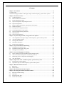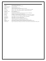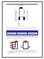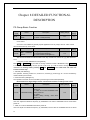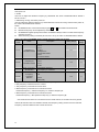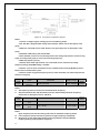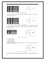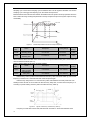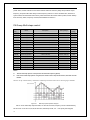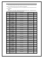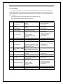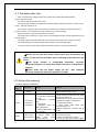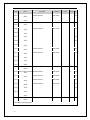
1
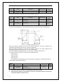
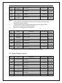
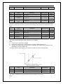
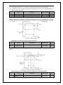
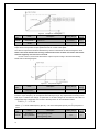
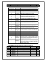
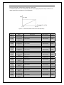
1:valid
Using P3.18 to increase ultilization of DC bus to raise output voltage when system work with full
load and low grid voltage(85% rated voltage below) for long time.
Function
Code
Name
P3.19
Operation mode of
cooling fans
Description
0: Automatics stopping
1: Operating all the time
Setting Range
Factory
Setting
0~1
0
0: Automatic stopping: Cooling fans works during system operation time, the fans stop after 30s of
the system stopped.
1:The fan works all the time when the system power on.
Function
Code
P3.20
Description
Setting Range
Factory
Setting
0.1~3600.0s,0.0Alarm function invalid
0.0~3600.0s
0.0s
Name
Alarm
intervals
reset
Notice:
Alarm reset intervals is used for alarm when system come out unusual status, which is not
serious enough cause damage, But it may lead to error.
User can use P3.20 to select whether it need alarm report or not and reset intervals.
P4 Group V/F Control
The parameters of the Group only valid for V/F control(P0.00=0)
Function
Name
Description
Code
0:Linear curve
1: User-defined curve
V/F curve
P4.00
2: Torque_stepdown curve (1.3 order)
selection
3: Torque_stepdown curve (1.7 order)
4: Torque_stepdown curve (2.0 order)
Setting Range
Factory
Setting
0~4
0
0: Linear curve. It is applicable for normal constant torque load.
1: User-defined curve. It can be defined through setting (P4.03~P4.08).
2~4: Torque_stepdown curve. It is applicable for variable torque load, such as blower, pump and so on.
Please refer to following figure.
59