1
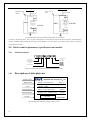
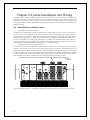
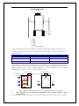
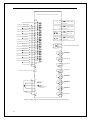
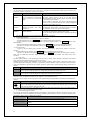
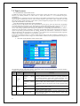
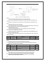
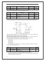
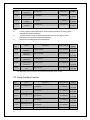
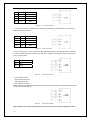
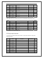
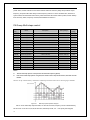
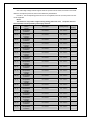
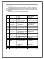
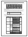
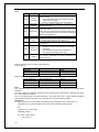
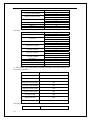
Figure 29 A,B channel combination diagram
Notice:
1. Current or voltage signals of alalog input is selectable by jumper.
2. AI1, AI2, AI3 is programmable analog input terminals, Please refer to description of P5
group.
3. When the command source is HDI, Please set its percentage refer to description of P5
group.
4. Standard of HDI setting: 24V,0.0~50.0kHz.
5. when P0.03=5, inverter run in multi-step, Please refer to P5 group termial to select running
stage, according to PA group to select current running frequency.
6. Multi-step speed is priority.
7. P0.03=5 :when multi-step terminal is 0, A command source come from first stage
frequency setting, UP/DOWN setting is availabe.
8. P0.03=7: user can write A command source in 2000H location through Modbus protocol.
Please refer to communication parts.
9. P0.06 is used to set general frequency source, status of P0.06(0,1,2) switched by terminal
function in P5 group.
Function
Code
Name
P0.07
Maximum
frequency
Description
P0.08~120.00Hz
Setting Range
Factory
Setting
P0.08~120.00Hz
50.00Hz
Notice:
z
The frequency reference should not exceed maximum frequency.
z
Actual acceleration time and deceleration time are determined by maximum frequency.
Please refer to description of P0.11 and P0.12.
Function
Code
Name
P0.08
Upper frequency
limit
P0.09
Lower frequency
limit
Setting Range
Factory
Setting
P0.09~ P0.07
P0.09~ P0.07
50.00Hz
0.00 ~ P0.08
0.00 ~ P0.08
0.00Hz
Description
Notice:
z
z
50
Upper frequency limit should not be greater than the maximum frequency (P0.07).
Lower frequency limit should not be greater than upper frequency limit (P0.08).
Restrictions on the relationship between frequency: Maximun frequency≥Upper
frequency≥setting frequency≥lower frequency.