1
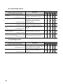
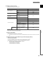
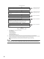
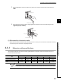
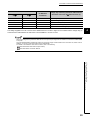
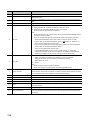
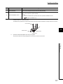
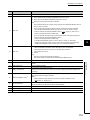
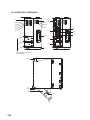
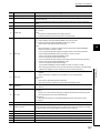
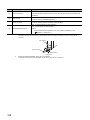
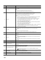
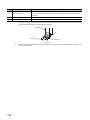
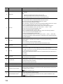
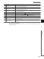
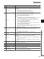
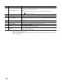
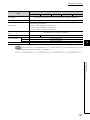
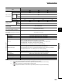
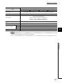
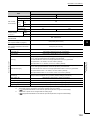
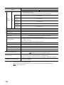
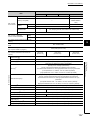
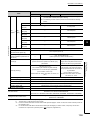
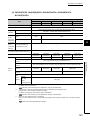
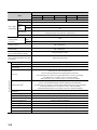
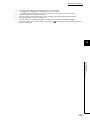
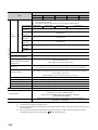
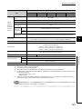
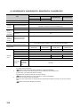
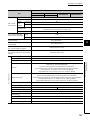
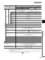
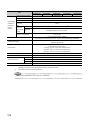
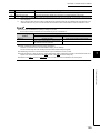
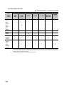
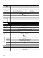
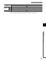
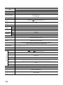
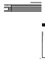
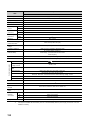
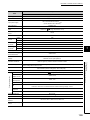
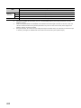
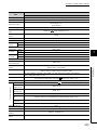
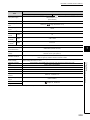
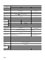
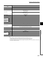
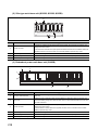
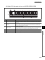
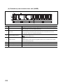
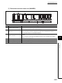
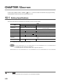
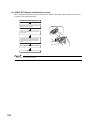
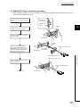
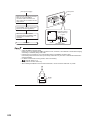
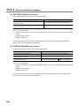
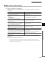
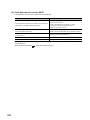
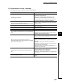
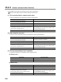
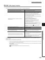
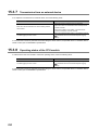
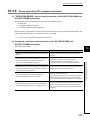
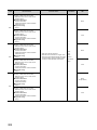
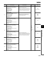
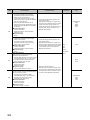
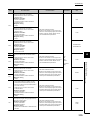
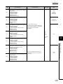
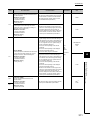
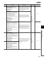
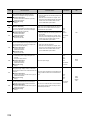
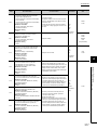
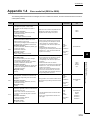
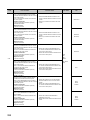
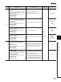
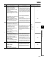
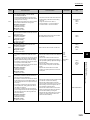
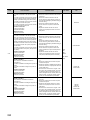
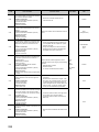
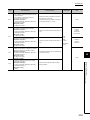
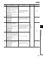
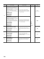
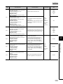
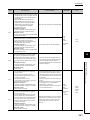
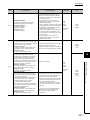
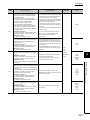
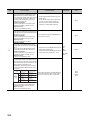
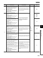
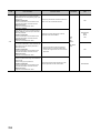
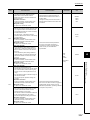
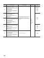
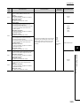
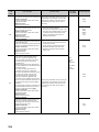
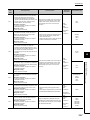
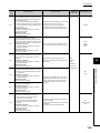
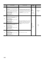
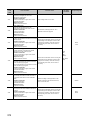
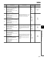
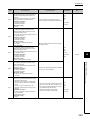
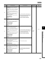
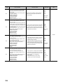
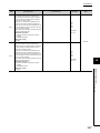
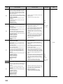
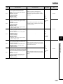
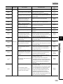
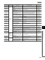
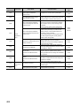
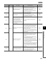
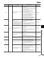
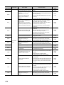
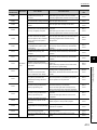
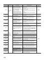
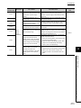
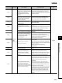
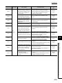
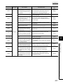
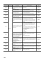
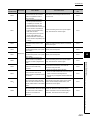
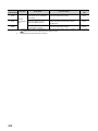
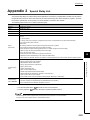
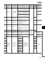
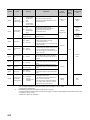
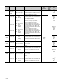
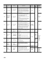
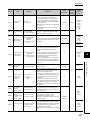
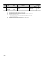
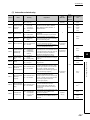
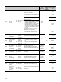
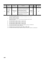
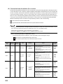
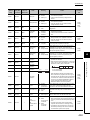
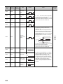
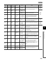
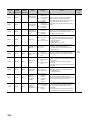
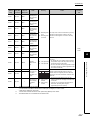
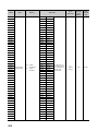
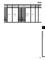
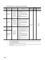
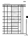
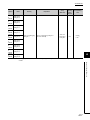
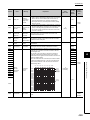
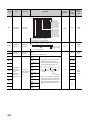
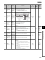
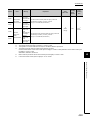
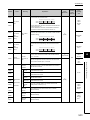
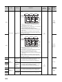
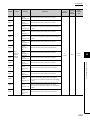
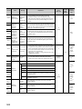
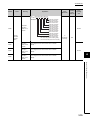
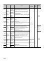
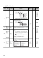
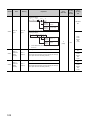
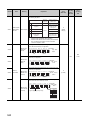
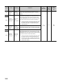
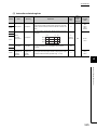
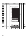
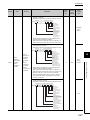
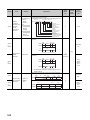
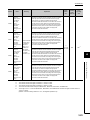
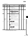
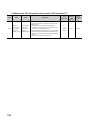
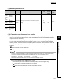
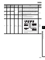
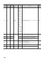
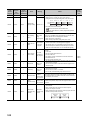
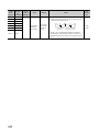
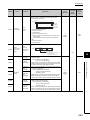
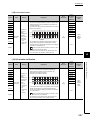
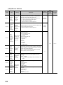
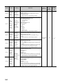
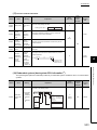
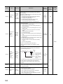
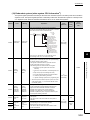
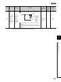
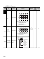
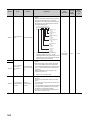
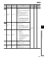
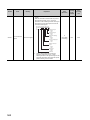
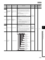
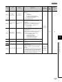
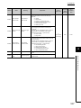
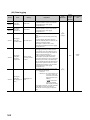
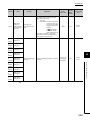
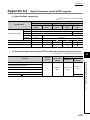
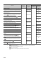
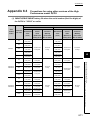
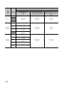
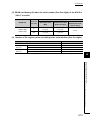
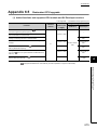
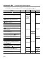
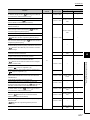
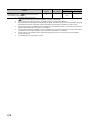
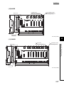
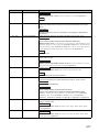
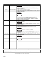
CHAPTER 7 POWER SUPPLY MODULE No. Name Application 16) Power input terminals Power input terminals for Q63P and connected to a 24VDC power supply. 17) Power input terminals Power input terminals for Q64P and connected to a 100VAC/200VAC power supply. *1 *2 Flicker-OFF indicates that the output signal of the terminal turns off and on at intervals of one second for three times and then off (opens). When using the Q61P-D in the system configured with an extension base unit, the POWER LED of the Q61P-D on the extension base unit may turn on in dull red when the module is turned off. Note that this does not indicate an error. ● The Q61P-A1 is dedicated for inputting a voltage of 100 VAC. Do not input a voltage of 200 VAC into it or trouble may occur on the Q61P-A1. Supply power voltage Power supply module Q61P-A1 Q61P-A2 100VAC 200VAC Operates normally. Power supply module causes trouble. Power supply module does not cause trouble. CPU module cannot be operated. Operates normally. ● Q64P automatically switches the input range 100/200VAC. Therefore, it cannot be used in the intermediate voltage (133 to 169VAC). The CPU module may not work normally if the above intermediate voltage is applied. ● Individually ground the LG and FG terminals with a ground resistance of 100 or less. ● When the Q61P-A1, Q61P-A2, Q61P-D, Q61P, Q62P, Q63P, Q64P or Q64PN is mounted on the extension base unit, a system error cannot be detected by the ERR. terminal. (The ERR. terminal is always off.) 7 ● Cables for the ERR. contact and LIFE OUT contact must be up to 30m and installed in the control panel. 7.1 Part Names and Settings 185