1
CHAPTER 4 INSTALLATION AND WIRING
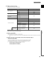
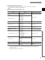
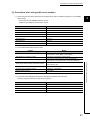
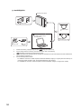
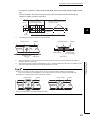
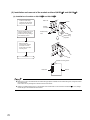
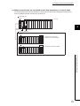
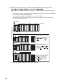
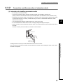
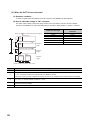
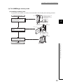
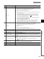
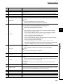
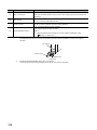
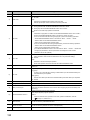
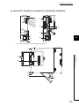
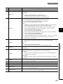
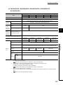
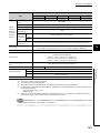
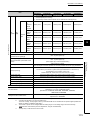
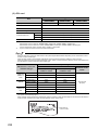
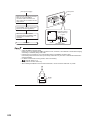
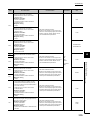
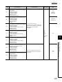
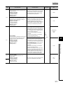
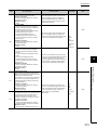
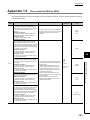
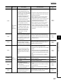
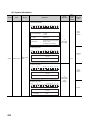
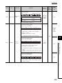
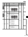
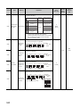
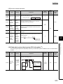
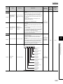
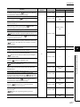
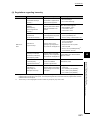
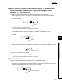
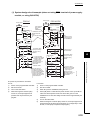
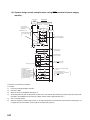
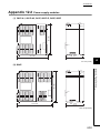
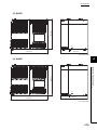
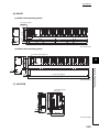
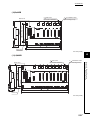
(b) In case of slim type main base unit
Indicates the panel top, wiring duct or any
part position.
30mm (1.18 inch)
or more
1, 5
5, 6
Programmable
controller
Panel
30mm (1.18 inch)
or more
4, 5
4
17 mm (0.67 inch) or more 2, 6
*1
*2
*3
*4
*5
*6
Door
4
20mm
(0.79 inch)
or more
3
5mm (0.20 inch) or more 6
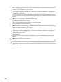
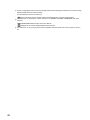
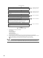
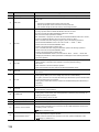
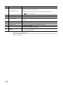
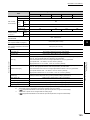
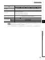
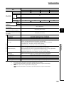
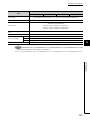
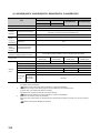
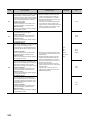
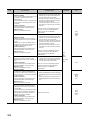
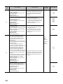
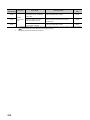
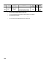
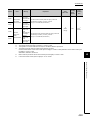
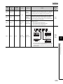
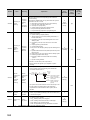
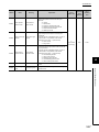
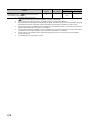
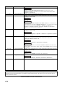
For wiring duct with 50mm (1.97 inches) or less height.
40mm (1.58 inches) or more for other cases.
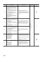
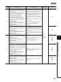
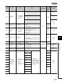
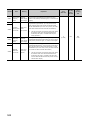
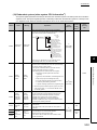
The cable of the power supply module of the slim type main base unit protrudes out of the left end of the module. Install
the module while reserving 17mm (0.67 inches) or more wiring space.
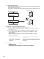
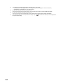
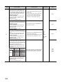
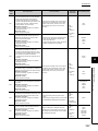
If the cable sheath is susceptible to damage caused by a structural object or part on the left side of the module, take a
protective measure with spiral tube or a similar insulator.
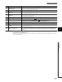
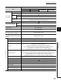
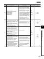
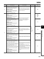
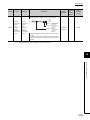
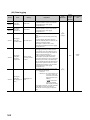
80mm (3.15 inches) or more for the connector type. 80mm (3.15 inches) or more for installing the Q8BAT cable when
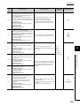
using the Q8BAT.
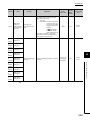
45mm (1.77 inches) or more when the Q7BAT is mounted.
30mm (1.18 inches) or more from the top and bottom of the Q8BAT when the Q8BAT is mounted.
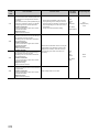
5mm (0.20 inches) or more from the right and left of the Q8BAT when the Q8BAT is mounted.
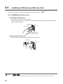
4.1 Installation Environment and Installation Position
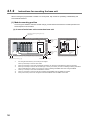
4.1.2 Instructions for mounting the base unit
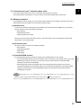
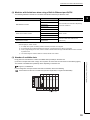
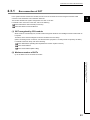
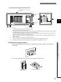
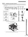
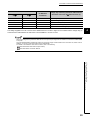
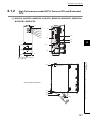
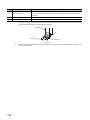
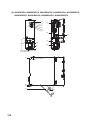
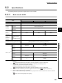
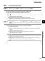
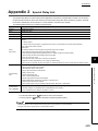
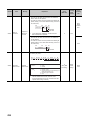
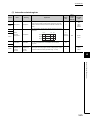
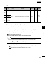
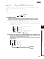
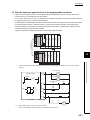
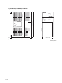
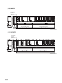
(2) Module mounting orientation
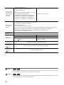
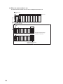
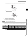
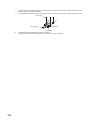
• To ensure good ventilation for heat dispassion, install the programmable controller in the orientation as
shown below.
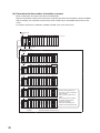
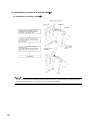
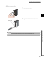
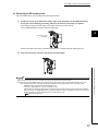
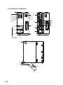
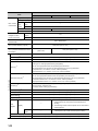
• Do not mount the programmable controller in the orientations as shown below.
Horizontal installation
Vertical mounting
57