1
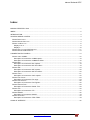
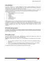
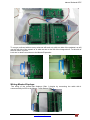
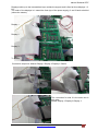
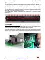
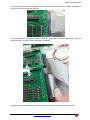
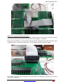
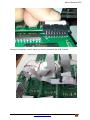
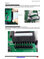
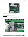
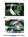
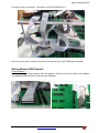
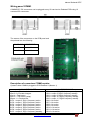
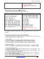
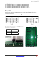
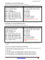
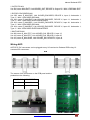
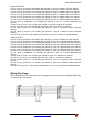
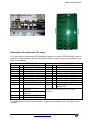
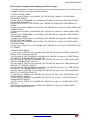
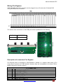
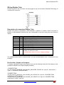
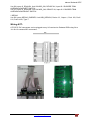
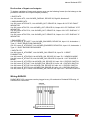
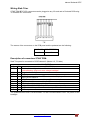
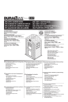
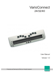
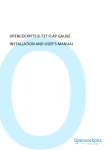
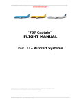
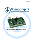
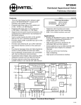
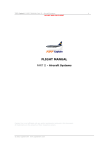
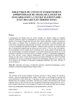
Date:23/06/14 Rev.:1.0 Manual Pedestal B737. Manual Pedestal B737 Index: MANUAL PEDESTAL B737. ........................................................................................................................ 1 INDEX:.......................................................................................................................................................... 2 INTRODUCTION: ......................................................................................................................................... 3 IOCARDS WIRING LAYERS :...................................................................................................................... 3 WIRING BASE LAYER:.................................................................................................................................. 3 WIRING MASTER-DISPLAYS: ........................................................................................................................ 4 WIRING THE DISPLAYS: ............................................................................................................................... 6 Displays 1 & 2:...................................................................................................................................... 6 Display 3: ............................................................................................................................................ 10 WIRING DISPLAYS AND PCB PEDESTAL: .................................................................................................... 11 WIRING MASTER-PCB PEDESTAL:............................................................................................................. 13 CONNECTING IDC PANELS: .................................................................................................................... 14 WIRING PANEL COMM:............................................................................................................................. 15 Description of connectors COMM captain:......................................................................................... 15 Description of connectors COMM first officer:.................................................................................... 16 WIRING NAV: ........................................................................................................................................... 17 Description of connectors NAV captain:............................................................................................. 18 Description of connectors NAV first officer:........................................................................................ 18 WIRING ADF: ........................................................................................................................................... 19 Description of connectors ADF captain: ............................................................................................. 20 Description of connectors ADF first officer: ........................................................................................ 20 WIRING AUDIO: ......................................................................................................................................... 21 Description of connectors Audio captain: ........................................................................................... 22 WIRING FIRE CARGO:................................................................................................................................ 23 Description of connectors Fire cargo:................................................................................................. 24 WIRING FIRE ENGINES: ............................................................................................................................. 26 Description of connectors Fire Engines:............................................................................................. 26 WIRING RUDDER TRIM: ............................................................................................................................. 29 Description of connectors Rudder Trim:............................................................................................. 29 WIRING ATC: ........................................................................................................................................... 30 Description of connectors ATC:.......................................................................................................... 31 WIRING RADAR:...................................................................................................................................... 32 Description of connectors RADAR: .................................................................................................... 33 WIRING STAB TRIM: .................................................................................................................................. 34 Description of connectors STAB TRIM:.............................................................................................. 34 LINKS OF INTEREST: ............................................................................................................................... 35 www.opencockpits.com 2 Manual Pedestal B737 Introduction: The B737 pedestal is a module designed to handle multiple parameters of radio, fire suppression, control audio, radar and rudder trim. This includes all the necessary electronics. All connected to the computer by USB only 2 or 3 cables. In addition it is designed for the user who does not have knowledge of welding or unwilling to manufacture cables by simply inserting mounting panels and cables IDC type connectors. The electronics included is: Power supply with 3,3V, 5V & 12V outputs. 1 USB Expansion. 2 Master. 6 Displays. 1 USB Servos. 1 USB DimmControl. 2 PCB Pedestal. In this manual we will try to explain the electronic wiring and assembly of panels IDC. The pedestal is designed as a layered system, Base Layer with electronic management (USB Expansion + 2 master), the Intermediate Layer with the secondary electronics (displays, control backlight brightness and servo), Layer Connections (PCB Pedestal) and finally the IDC modules. IOCards wiring layers : The layers of the pedestal are four three of them have active electronics, will see the wiring of each type of card at the end of mounting only have to connect the IDC terminals of IDC panels without making a single weld Wiring Base Layer: This layer contains the power supply, USB Expansion Card and two Master that connect via IDC ribbon cables to the cards of the intermediate layer. The power supply has three outputs: 3.3 V (orange-black), 5V (red-black) and 12V (yellowblack). The 12V output is optional in case a user wants to connect any additional lighting or electronics. The 3.3 V are to power the backlight panels via USB DimmControl (see your manual). The 5V feed both Masters and controlling USB Servo Rudder servo panel. The Expansion USB connects to the Masters using the 25-pin cable: www.opencockpits.com 3 Manual Pedestal B737 To not get confused with too many wires we will work only with one side of the pedestal, we will use the left side of the captain or is what we see to the left of the image above. To the side of the first officer is just as. Let's see in detail connections to the Master Expansion: Wiring Master-Displays: The wiring of the master-side displays (Side 1) begins by connecting the cable with 4 connectors 40-pin IDC to the Master 1 and displays Side 1: www.opencockpits.com 4 Manual Pedestal B737 Displays cable up to the intermediate layer outside the support and is fixed at three displays 1, 2 & 3. The order of the displays is 1 toward the front (top of the power supply), 2 and 3 back to behind (above the master): Display 1 Display 2 Display 3 To Master Connection sequence: Master-Display 2 Display 3 Display-1 Details: The connection for side 2 is the same but in this order: Master-Display 1-Display 2-Display 3. www.opencockpits.com 5 Manual Pedestal B737 Wiring the Displays: The wiring between the displays cards need a little more attention because we use three of them connected to the same Master. In addition two of them are connected to the PCB Pedestal by a single cable and the third with a separate connector of the other two. The connection between the displays 1 and 2 is made with 2 wires of 3 connector, one cable is 16 wires and the other cable 34 wires. The card displays using multiplexing technology to be identified up to four of them with the same cable, so you will use this feature to connect. For those who do not know the structure of the IDC connectors put an example to become familiar with it: Displays 1 & 2: Cable 34 contacts with three connectors. The 34 pin connector farthest from the other remains free to connect with pedestal card, the connector on the other end of the cable connects to the display 1 as follows: Row of pins on the display 1 card with the odd row of holes on the cable connector, matching the Pin 1 of each connector (pin 1 of the display with red thread the cable). Are free the last two holes of the 34-pin connector cable: www.opencockpits.com 6 Manual Pedestal B737 As you can see in the picture (adapted for the display card manual) pins 1 match and holes 33 and 34 of the cable connector are free. The next step is to connect the display 1 display 2 using the connector cable is free. Use this connector pairs row holes, being free holes 33 and 34: Lagging follows the cable ready to climb the next layer PCB and connect with Pedestal. www.opencockpits.com 7 Manual Pedestal B737 Cable of 16 contact with three connectors. The connector 16 further from other contacts remains free to connect with pedestal card, the connector on the other end of the cable connects to the display 1 as follows: Row 8 pin of the display 1 (J6 connector) with the odd row of holes on the cable connector, card matching the Pin 1 of each connector (pin 1 of the display with red thread the cable): The central connector cable connects to the connector J6 of display 2 using the row of pairs holes in the connector: www.opencockpits.com 8 Manual Pedestal B737 Being all the displays 1 and 2 with a free end for connecting the PCB Pedestal: www.opencockpits.com 9 Manual Pedestal B737 Display 3: Cable of 34 contacts with 2 connectors. Now we will make the 34 wires cable connection with Display 3. This cable has only two connectors, one for PCB Pedestal and one for the display, the latter used the row of odd contacts, matching pin 1 of both connectors and being free contacts 33 and 34: Being like: Cable of 16 contacts with two connectors. The cable connector is connected to the display 3 as follows: Row of 8 pins of the display 3 board (J6 connector) with odd row cable connector holes, matching the Pin 1 of each connector (pin 1 of the display with red thread the cable), just like the card display 1: www.opencockpits.com 10 Manual Pedestal B737 Being wiring Display 3 as well: Now is connect free terminals to the card PCB Pedestal. Wiring Displays and PCB Pedestal: Displays 1 & 2: The wires of displays 1 and 2 are connected to pedestal card 1 to their respective ports: Wire connector 34 contacts - Connector 34 pins PCB DISPLAY 1/2. www.opencockpits.com 11 Manual Pedestal B737 Connector wire 16 contacts - Connector 16 pins PCB DISPLAY 1/2. Display 3: The display 3 cable is connected to the pedestal card 1 in their respective ports: Connector cable of 34 contacts - Connector 34 pins PCB DISPLAY 3. www.opencockpits.com 12 Manual Pedestal B737 Connector cable 16 contacts - Connector 16 pins PCB DISPLAY 3. Now we will see how to connect the inputs and outputs of the card PCB Master Pedestal. Wiring Master-PCB Pedestal: Outputs Master 1: The output wiring is much simpler than the displays. Simply connect the output of the Master (J2) with MASTER OUTPUTS connector pcb Pedestal: www.opencockpits.com 13 Manual Pedestal B737 Inputs Master 1: The input wiring is the same as the outputs. Just connect the inputs of the Master (J3 and J4) to the MASTER INPUTS 1 & 2 of PCB Pedestal. Inputs 2: Inputs 1: It only remains to connect the IDC modules to the PCB Pedestal card, each of them has in its own connector. Connecting IDC panels: Ech IDC panel has its own connector on the PCB Pedestal board, with the following specifications: SIDE 1 CAPTAIN COMM NAV ADF AUDIO FIRE ENGINES RUDDER TRIM RADAR SIDE 2 FIRST OFFICER COMM NAV ADF AUDIO FIRE CARGO ATC STAB TRIM This is because the fire cargo and the fire engine panels can not be connected to the same card, just like the ATC. www.opencockpits.com 14 Manual Pedestal B737 Wiring panel COMM: COMM B737 IDC connectors can be plugged to any I/O card and to Pedestal PCB using 16 contacts IDC connectors: The names of the connectors on the PCB panel and the pedestal are the following: PANEL IDC PCB PEDESTAL J3 J10 J2 J9 Description of connectors COMM captain: Cpatain's side COMM is plugged to PCB Pedestal 1 (Master 1). J10 CONNECTOR LEFT Inputs 0-1 = Encoder decimals. Input 2-3 = Encoder integers. Input 4 = Test button. Input 5 = TFR button (swap). Output 11 = Decimal dot. D1S1 = output 0, Digit 1 frequency active. D1S2 = output 1, Digit 2 frequency active. D1S3 = output 2, Digit 3 frequency active. D1S4 = output 3, Digit 4 frequency active. D1S5 = output 4, Digit 5 frequency active. D1S6 = output 5, Digit 6 frequency active. D1S7 = output 6, Digit 1 frequency standby. J9 CONNECTOR RIGHT D1D1 = output 7, Digit 2 frequency standby. D1D2 = output 8, Digit 3 frequency standby. D1D3 = output 9, Digit 4 frequency standby. D1D4 = output 10, Digit 5 frequency standby. D1D5 = output 11, Digit 6 frequency standby. D1D6 = No active. D1D7 = No active. D1D8 = No active. D1D9 = No active. D1D10 = No active. D1D11 = No active. D1D12 = No active. www.opencockpits.com 15 Manual Pedestal B737 GND1 = COMMON or GND. DO11 = Negative backlight. PLED = Positive backlight. Are needed 2.5 volts to 2.9 volts. ¡ActiveWarning: may burn more voltage backlight! Description of connectors COMM first officer: First officer COMM is connected to PCB Pedestal 2 (Master nº2). J10 CONNECTOR LEFT Inputs 72-73 = Encoder decimals. Input 74-75 = Encoder integers. Input 76 = Test button. Input 77 = TFR button (swap). Output 75 = decimal dot. D1S1 = output 64, Digit 1 frequency active. D1S2 = output 65, Digit 2 frequency active. D1S3 = output 66, Digit 3 frequency active. D1S4 = output 67, Digit 4 frequency active. D1S5 = output 68, Digit 5 frequency active. D1S6 = output 69, Digit 6 frequency active. D1S7 = output 70, Digit 1 frequency standby. GND1 = COMMON or GND. J9 CONNECTOR RIGHT D1D1 = output 71, Digit 2 frequency standby. D1D2 = output 72, Digit 3 frequency standby. D1D3 = output 73, Digit 4 frequency standby. D1D4 = output 74, Digit 5 frequency standby. D1D5 = output 75, Digit 6 frequency standby. D1D6 = No active. D1D7 = No active. D1D8 = No active. D1D9 = No active. D1D10 = No active. D1D11 = No active. D1D12 = No active. DO11 = Negative for backlight. PLED = Positive for backlight. It takes 2.5 volts to 2.9 volts. ¡ActiveWarning: may burn more voltage backlight! The USBDimcontrol card is recommended. It is also recommended to use 3 volt power for the backlight. Declaration of inputs and outputs Panel COMM IDC: To declare variables of inputs and outputs must use the following format (the list belongs to the pedestal's definition file of Opencockpits pedestal). // DIGITS COMM Var 100, name CM1ACT, Link IOCARD_DISPLAY, DEVICE X, Digit 0, Numbers 6 Var 102, name CM1STBY, Link IOCARD_DISPLAY, DEVICE X, Digit 6, Numbers 6 Var 104, name CM2ACT, Link IOCARD_DISPLAY, DEVICE X, Digit 64, Numbers 6 Var 106, name CM2STBY, Link IOCARD_DISPLAY, DEVICE X, Digit 70, Numbers 6 // OUTPUTS COMM Var 200, name COM1DOT, Link IOCARD_OUT, DEVICE X, Output 11 // COMM 1 DECIMAL Var 202, name COM2DOT, Link IOCARD_OUT, DEVICE X, Output 75 // COMM 2 DECIMAL // ROTARY ENCODERS COMM Var 350, name E_CM1DEC, Link IOCARD_ENCODER, DEVICE X, Input 0, Aceleration 1, Type 2 // COMM 1 ENCODER DECIMAL Var 352, name E_CM1ENT, Link IOCARD_ENCODER, DEVICE X, Input 2, Aceleration 1, Type 2 // COMM 1 ENCODER ENTEROS/INTEGER Var 354, name E_CM2DEC, Link IOCARD_ENCODER, DEVICE X, Input 72, Aceleration 1, Type 2 // COMM 2 ENCODER DECIMAL Var 356, name E_CM2ENT, Link IOCARD_ENCODER, DEVICE X, Input 74, Aceleration 1, Type 2 // COMM 2 ENCODER ENTEROS/INTEGER www.opencockpits.com 16 Manual Pedestal B737 // SWITCHES COMM Var 400, name S_CM1TST, Link IOCARD_SW, DEVICE X, Input 4 Var 402, name S_CM2TST, Link IOCARD_SW, DEVICE X, Input 76 Var 404, name S_CM1SWP, Link IOCARD_SW, DEVICE X, Input 5 Var 406, name S_CM2SWP, Link IOCARD_SW, DEVICE X, Input 77 Wiring NAV: NAV B737 IDC connectors can be plugged to any I/O card and to Pedestal PCB using 16 contacts IDC connectors: The names of the connectors on the PCB panel and the pedestal are the following: PANEL IDC PCB PEDESTAL J3 J12 J2 J11 www.opencockpits.com 17 Manual Pedestal B737 Description of connectors NAV captain: Captain's side NAV is connected to PCB Pedestal 1 (Master nº1). J12 CONNECTOR LEFT Inputs 9-10 = Encoder decimals. Input 11-12 = Encoder integers. Input 13 = Test button. Input 14 = TFR button (swap). Output 12 = Decimal dot. D2S1 = output 16, Digit 1 frequency active. D2S2 = output 17, Digit 2 frequency active. D2S3 = output 18, Digit 3 frequency active. D2S4 = output 19, Digit 4 frequency active. D2S5 = output 20, Digit 5 frequency active. D2S6 = output 21, Digit 1 frequency standby. D2S7 = output 22, Digit 2 frequency standby. GND2 = COMMON or GND. J11 CONNECTOR RIGHT D2D1 = output 23, Digit 3 frequency standby. D2D2 = output 24, Digit 4 frequency standby. D2D3 = output 25, Digit 5 frequency standby. D2D4 = No active. D2D5 = No active. D2D6 = No active. D2D7 = No active. D2D8 = No active. D2D9 = No active. D2D10 = No active. DO12 = Negative for backlight. PLED = Positive for backlight. It takes 2.5 volts to 2.9 volts. ¡ActiveWarning: may burn more voltage backlight! Description of connectors NAV first officer: First officer NAVis connected to PCB Pedestal 2 (Master nº2). J12 CONNECTOR LEFT Inputs 81-82 = Encoder decimals. Input 83-84 = Encoder integers. Input 85 = Test button. Input 86 = TFR button (swap). Output 76 = Decimal dot. D2S1 = output 80, Digit 1 frequency active. D2S2 = output 81, Digit 2 frequency active. D2S3 = output 82, Digit 3 frequency active. D2S4 = output 83, Digit 4 frequency active. D2S5 = output 84, Digit 5 frequency active. D2S6 = output 85, Digit 1 frequency standby. D2S7 = output 86, Digit 2 frequency standby. GND2 = COMMON or GND. J11 CONNECTOR RIGHT D2D1 = output 87, Digit 3 frequency standby. D2D2 = output 88, Digit 4 frequency standby. D2D3 = output 89, Digit 5 frequency standby. D2D4 = No active. D2D5 = No active. D2D6 = No active. D2D7 = No active. D2D8 = No active. D2D9 = No active. D2D10 = No active. DO12 = Negative for backlight. PLED = Positive for backlight. It takes 2.5 volts to 2.9 volts. ¡ActiveWarning: may burn more voltage backlight! The USBDimcontrol card is recommended. It is also recommended to use 3 volt power for the backlight. Declaration of inputs and outputs panel NAV IDC: To declare variables of inputs and outputs must use the following format (the list belongs to the pedestal's definition file of Opencockpits pedestal). // DIGITS NAV Var 108, name NV1ACT, Link IOCARD_DISPLAY, DEVICE X, Digit 16, Numbers 5 Var 110, name NV1STBY, Link IOCARD_DISPLAY, DEVICE X, Digit 21, Numbers 5 Var 112, name NV2ACT, Link IOCARD_DISPLAY, DEVICE X, Digit 80, Numbers 5 Var 114, name NV2STBY, Link IOCARD_DISPLAY, DEVICE X, Digit 85, Numbers 5 www.opencockpits.com 18 Manual Pedestal B737 // OUTPUTS NAV Var 204, name NAV1DOT, Link IOCARD_OUT, DEVICE X, Output 12 // NAV 1 DECIMAL DOT Var 206, name NAV2DOT, Link IOCARD_OUT, DEVICE X, Output 76 // NAV 2 DECIMAL DOT // ROTARY ENCODERS NAV Var 358, name E_NAV1DEC, Link IOCARD_ENCODER, DEVICE X, Input 9, Type 2 // NAV 1 ENCODER DECIMAL Var 360, name E_NAV1ENT, Link IOCARD_ENCODER, DEVICE X, Input 11, Type 2 // NAV 1 ENCODER ENTEROS/INTEGER Var 362, name E_NAV2DEC, Link IOCARD_ENCODER, DEVICE X, Input 81, Type 2 // NAV 2 ENCODER DECIMAL Var 364, name E_NAV2ENT, Link IOCARD_ENCODER, DEVICE X, Input 83, Type 2 // NAV 2 ENCODER ENTEROS/INTEGER Aceleration 1, Aceleration 1, Aceleration 1, Aceleration 1, // SWITCHES NAV Var 408, name S_NAV1TST, Link IOCARD_SW, DEVICE X, Input 13 Var 410, name S_NAV2TST, Link IOCARD_SW, DEVICE X, Input 85 Var 412, name S_NAV1SWP, Link IOCARD_SW, DEVICE X, Input 14 Var 414, name S_NAV2SWP, Link IOCARD_SW, DEVICE X, Input 86 Wiring ADF: ADF B737 IDC connectors can be plugged to any I/O card and to Pedestal PCB using 16 contacts IDC connectors: The names of the connectors on the PCB panel and the pedestal are the following: PANEL IDC PCB PEDESTAL J3 J14 J2 J13 www.opencockpits.com 19 Manual Pedestal B737 Description of connectors ADF captain: Captain's ADF is connected to PCB Pedestal 1 (Master nº1). J14 CONNECTOR LEFT Inputs 18-19 = Encoder decimals. Input 20-21 = Encoder integers. Input 22 = Button ADF/ANT. Input 23 = TFR button (swap). Input 24 = Button TONE. Output 13 = Decimal dot. D3S1 = output 32, Digit 1 frequency active. D3S2 = output 33, Digit 2 frequency active. D3S3 = output 34, Digit 3 frequency active. D3S4 = output 35, Digit 4 frequency active. D3S5 = output 36, Digit 5 frequency active. D3S6 = output 37, Digit 1 frequency standby. D3S7 = output 38, Digit 2 frequency standby. GND3 = COMMON or GND for inputs. J13 CONNECTOR RIGHT D3D1 = output 39, Digit 3 frequency standby. D3D2 = output 40, Digit 4 frequency standby. D3D3 = output 41, Digit 5 frequency standby. D3D11 = output 42, indicator ADF frec. active. D3D12 = output 43, indicator ANT frec. active. D3D13 = output 44, indicator ANT frec. standby. D3D14 = output 45, indicator ADF frec. standby. D3D11...D14 are On when take value 0 and are off when take value 1. D3D4...D10 = No actives. DO13 = Negative for backlight. PLED = Positive for backlight. It takes 2.5 volts to 2.9 volts. ¡ActiveWarning: may burn more voltage backlight! Description of connectors ADF first officer: First officer ADF is connected to PCB Pedestal 2 (Master nº2). J14 CONNECTOR LEFT Inputs 90-91 = Encoder decimals. Input 92-93 = Encoder integers. Input 94 = Button ADF/ANT. Input 95 = TFR button (swap). Input 96 = Button TONE. Output 77 = Decimal dot. D3S1 = output 96, Digit 1 frequency active. D3S2 = output 97, Digit 2 frequency active. D3S3 = output 98, Digit 3 frequency active. D3S4 = output 99, Digit 4 frequency active. D3S5 = output 100, Digit 5 frequency active. D3S6 = output 101, Digit 1 frequency standby. D3S7 = output 102, Digit 2 frequency standby. GND3 = COMMON or GND. J13 CONNECTOR RIGHT D3D1 = output 103, Digit 3 frequency standby. D3D2 = output 104, Digit 4 frequency standby. D3D3 = output 105, Digit 5 frequency standby. D3D11 = output 106, indicator ADF frec. active. D3D12 = output 107, indicator ANT frec. active. D3D13 = output 108, indicator ANT frec. standby. D3D14 = output 109, indicator ADF frec. standby. D3D11...D14 are on when take value 0 and off when take value 1. D3D4...D10 = No actives. DO13 = Negative for backlight. PLED = Positive for backlight. It takes 2.5 volts to 2.9 volts. ¡ActiveWarning: may burn more voltage backlight! The USBDimcontrol card is recommended. It is also recommended to use 3 volt power for the backlight. www.opencockpits.com 20 Manual Pedestal B737 Declaration of inputs and outputs panel ADF IDC: To declare variables of inputs and outputs must use the following format (the list belongs to the pedestal's definition file of Opencockpits pedestal). // DIGITS ADF Var 116, name ADF1ACT, Link IOCARD_DISPLAY, DEVICE X, Digit 32, Numbers 5 Var 118, name ADF1STBY, Link IOCARD_DISPLAY, DEVICE X, Digit 37, Numbers 5 Var 120, name ANT1ACT, Link IOCARD_DISPLAY, DEVICE X, Digit 43, Numbers 1 Var 122, name ANT1STBY, Link IOCARD_DISPLAY, DEVICE X, Digit 44, Numbers 1 Var 124, name ADF1A, Link IOCARD_DISPLAY, DEVICE X, Digit 42, Numbers 1 Var 126, name ADF1S, Link IOCARD_DISPLAY, DEVICE X, Digit 45, Numbers 1 Var 128, name ADF2ACT, Link IOCARD_DISPLAY, DEVICE X, Digit 96, Numbers 5 Var 130, name ADF2STBY, Link IOCARD_DISPLAY, DEVICE X, Digit 101, Numbers 5 Var 132, name ANT2ACT, Link IOCARD_DISPLAY, DEVICE X, Digit 107, Numbers 1 Var 134, name ANT2STBY, Link IOCARD_DISPLAY, DEVICE X, Digit 108, Numbers 1 Var 136, name ADF2A, Link IOCARD_DISPLAY, DEVICE X, Digit 106, Numbers 1 Var 138, name ADF2S, Link IOCARD_DISPLAY, DEVICE X, Digit 109, Numbers 1 // OUTPUTS ADF Var 208, name ADF1DOT, Link IOCARD_OUT, DEVICE X, Output 13 // ADF 1 DECIMAL DOT Var 210, name ADF2DOT, Link IOCARD_OUT, DEVICE X, Output 77 // ADF 2 DECIMAL DOT // ROTARY ENCODERS ADF Var 366, name E_ADF1DEC, Link IOCARD_ENCODER, Type 2 // ADF 1 ENCODER DECIMAL Var 368, name E_ADF1ENT, Link IOCARD_ENCODER, Type 2 // ADF 1 ENCODER ENTEROS/INTEGER Var 370, name E_ADF2DEC, Link IOCARD_ENCODER, Type 2 // ADF 1 ENCODER DECIMAL Var 372, name E_ADF2ENT, Link IOCARD_ENCODER, Type 2 // ADF 1 ENCODER ENTEROS/INTEGER DEVICE X, Input 18, Aceleration 1, DEVICE X, Input 20, Aceleration 1, DEVICE X, Input 90, Aceleration 1, DEVICE X, Input 92, Aceleration 1, // SWITCHES ADF Var 416, name S_ADF1SWP, Link IOCARD_SW, DEVICE X, Input 23 Var 418, name S_ADF2SWP, Link IOCARD_SW, DEVICE X, Input 95 Var 420, name S_ADF1ANT, Link IOCARD_SW, DEVICE X, Input 22 Var 422, name S_ADF2ANT, Link IOCARD_SW, DEVICE X, Input 94 Var 424, name S_ADF1TONE, Link IOCARD_SW, DEVICE X, Input 24 Var 426, name S_ADF2TONE, Link IOCARD_SW, DEVICE X, Input 96 Wiring Audio: Audio B737 IDC connectors can be plugged to any I/O card, to the Audio P&P module and to Pedestal PCB using 16 contacts IDC connectors. www.opencockpits.com 21 Manual Pedestal B737 Connections to other modules or PCB Pedestal: PANEL Connector J1: Connector J2: MODULE AUDIO P&P J5 audio module connector J6 audio module connector PCB PEDESTAL J15 pcb pedestal connector J16 pcb pedestal connector Description of connectors Audio captain: J15 CONNECTOR I27 = AUDIO1 VHF1 MIC SWITCH I28 = AUDIO1 VHF2 MIC SWITCH I29 = AUDIO1 VHF1 VOL SWITCH I30 = AUDIO1 VHF2 VOL SWITCH I31 = AUDIO1 NAV1 VOL SWITCH I32 = AUDIO1 NAV2 VOL SWITCH I33 = AUDIO1 ADF1 VOL SWITCH I34 = AUDIO1 ADF2 VOL SWITCH I35 = AUDIO1 MARKER VOL SWITCH I36 = AUDIO1 FILTER R ROTARY SWITCH I37 = AUDIO1 FILTER V ROTARY SWITCH I38 = AUDIO1 R-T SWITCH I39 = AUDIO1 I-C SWITCH I40 = AUDIO1 ALT-NORM SWITCH GND4 = COMMON for inputs: 27, 28, 29, 30, 31, 32, 33, 34 and 35. GND5 = COMMON for inputs: 36, 37, 38, 39 and 40. (For Cards without common inputs, you should join GND4 and GND5) J16 CONNECTOR GND = Negative for outputs. (for outputs it takes +5 volts). O14 = AUDIO1 VHF1 MIC LED O15 = AUDIO1 VHF2 MIC LED O16 = AUDIO1 VHF1 VOL LED O17 = AUDIO1 VHF2 VOL LED O18 = AUDIO1 NAV1 VOL LED O19 = AUDIO1 NAV2 VOL LED O20 = AUDIO1 ADF1 VOL LED O21 = AUDIO1 ADF2 VOL LED O22 = AUDIO1 MARKER VOL LED DO31 = Negative for backlight. PLED = Positive for backlight. It takes 2.5 volts to 2.9 volts. ¡ActiveWarning: may burn more voltage backlight! The USBDimcontrol card is recommended. It is also recommended to use 3 volt power for the backlight. Declaration of inputs and outputs: To declare variables of inputs and outputs must use the following format (the list belongs to the pedestal's definition file of Opencockpits pedestal). Outputs Audio CAP: Var 212, name AU1VH1MI, Link IOCARD_OUT, DEVICE X, Output 14 // AUDIO1 VHF1 MIC LED Var 214, name AU1VH2MI, Link IOCARD_OUT, DEVICE X, Output 15 // AUDIO1 VHF2 MIC LED Var 216, name AU1VH1VO, Link IOCARD_OUT, DEVICE X, Output 16 // AUDIO1 VHF1 VOL LED Var 218, name AU1VH2VO, Link IOCARD_OUT, DEVICE X, Output 17 // AUDIO1 VHF2 VOL LED Var 220, name AU1NA1VO, Link IOCARD_OUT, DEVICE X, Output 18 // AUDIO1 NAV1 VOL LED Var 222, name AU1NA2VO, Link IOCARD_OUT, DEVICE X, Output 19 // AUDIO1 NAV2 VOL LED Var 224, name AU1AD1VO, Link IOCARD_OUT, DEVICE X, Output 20 // AUDIO1 ADF1 VOL LED Var 226, name AU1AD2VO, Link IOCARD_OUT, DEVICE X, Output 21 // AUDIO1 ADF2 VOL LED Var 228, name AU1MKRVO, Link IOCARD_OUT, DEVICE X, Output 22 // AUDIO1 MARKER VOL LED Outputs Audio FO: Var 230, name AU2VH1MI, Link IOCARD_OUT, DEVICE X, Output 78 // AUDIO2 VHF1 MIC LED Var 232, name AU2VH2MI, Link IOCARD_OUT, DEVICE X, Output 79 // AUDIO2 VHF2 MIC LED Var 234, name AU2VH1VO, Link IOCARD_OUT, DEVICE X, Output 80 // AUDIO2 VHF1 VOL LED Var 236, name AU2VH2VO, Link IOCARD_OUT, DEVICE X, Output 81 // AUDIO2 VHF2 VOL LED Var 238, name AU2NA1VO, Link IOCARD_OUT, DEVICE X, Output 82 // AUDIO2 NAV1 VOL LED Var 240, name AU2NA2VO, Link IOCARD_OUT, DEVICE X, Output 83 // AUDIO2 NAV2 VOL LED Var 242, name AU2AD1VO, Link IOCARD_OUT, DEVICE X, Output 84 // AUDIO2 ADF1 VOL LED Var 244, name AU2AD2VO, Link IOCARD_OUT, DEVICE X, Output 85 // AUDIO2 ADF2 VOL LED Var 246, name AU2MKRVO, Link IOCARD_OUT, DEVICE X, Output 86 // AUDIO2 MARKER VOL LED www.opencockpits.com 22 Manual Pedestal B737 Inputs Audio CAP: Var 444, name S_AU1VH1MI, Link IOCARD_SW, DEVICE X, Input 27 // AUDIO1 VHF1 MIC SWITCH Var 446, name S_AU1VH2MI, Link IOCARD_SW, DEVICE X, Input 28 // AUDIO1 VHF2 MIC SWITCH Var 448, name S_AU1VH1VO, Link IOCARD_SW, DEVICE X, Input 29 // AUDIO1 VHF1 VOL SWITCH Var 450, name S_AU1VH2VO, Link IOCARD_SW, DEVICE X, Input 30 // AUDIO1 VHF2 VOL SWITCH Var 452, name S_AU1NA1VO, Link IOCARD_SW, DEVICE X, Input 31 // AUDIO1 NAV1 VOL SWITCH Var 454, name S_AU1NA2VO, Link IOCARD_SW, DEVICE X, Input 32 // AUDIO1 NAV2 VOL SWITCH Var 456, name S_AU1AD1VO, Link IOCARD_SW, DEVICE X, Input 33 // AUDIO1 ADF1 VOL SWITCH Var 458, name S_AU1AD2VO, Link IOCARD_SW, DEVICE X, Input 34 // AUDIO1 ADF2 VOL SWITCH Var 460, name S_AU1MKRVO, Link IOCARD_SW, DEVICE X, Input 35 // AUDIO1 MARKER VOL SWITCH Var 462, name S_AU1RT, Link IOCARD_SW, DEVICE X, Input 38 // AUDIO1 R-T SWITCH Var 464, name S_AU1IC, Link IOCARD_SW, DEVICE X, Input 39 // AUDIO1 I-C SWITCH Var 466, name R_AU1FILTV, Link IOCARD_SW, DEVICE X, Input 37 // AUDIO1 FILTER V ROTARY SWITCH Var 468, name R_AU1FILTR, Link IOCARD_SW, DEVICE X, Input 36 // AUDIO1 FILTER R ROTARY SWITCH Var 470, name S_AU1ALT, Link IOCARD_SW, DEVICE X, Input 40 // AUDIO1 ALT-NORM SWITCH Inputs Audio FO: Var 472, name S_AU2VH1MI, Link IOCARD_SW, DEVICE X, Input 99 // AUDIO2 VHF1 MIC SWITCH Var 474, name S_AU2VH2MI, Link IOCARD_SW, DEVICE X, Input 100 // AUDIO2 VHF2 MIC SWITCH Var 476, name S_AU2VH1VO, Link IOCARD_SW, DEVICE X, Input 101 // AUDIO2 VHF1 VOL SWITCH Var 478, name S_AU2VH2VO, Link IOCARD_SW, DEVICE X, Input 102 // AUDIO2 VHF2 VOL SWITCH Var 480, name S_AU2NA1VO, Link IOCARD_SW, DEVICE X, Input 103 // AUDIO2 NAV1 VOL SWITCH Var 482, name S_AU2NA2VO, Link IOCARD_SW, DEVICE X, Input 104 // AUDIO2 NAV2 VOL SWITCH Var 484, name S_AU2AD1VO, Link IOCARD_SW, DEVICE X, Input 105 // AUDIO2 ADF1 VOL SWITCH Var 486, name S_AU2AD2VO, Link IOCARD_SW, DEVICE X, Input 106 // AUDIO2 ADF2 VOL SWITCH Var 488, name S_AU2MKRVO, Link IOCARD_SW, DEVICE X, Input 107 // AUDIO2 MARKER VOL SWITCH Var 490, name S_AU2RT, Link IOCARD_SW, DEVICE X, Input 110 // AUDIO2 R-T SWITCH Var 492, name S_AU2IC, Link IOCARD_SW, DEVICE X, Input 111 // AUDIO2 I-C SWITCH Var 494, name R_AU2FILTV, Link IOCARD_SW, DEVICE X, Input 109 // AUDIO2 FILTER V ROTARY SWITCH Var 496, name R_AU2FILTR, Link IOCARD_SW, DEVICE X, Input 108 // AUDIO2 FILTER R ROTARY SWITCH Var 498, name S_AU2ALT, Link IOCARD_SW, DEVICE XX, Input 112 // AUDIO2 ALT-NORM SWITCH Wiring Fire Cargo: FIRE CARGO B737 IDC connectors can be plugged to any I/O card and to Pedestal PCB using 16 contacts IDC connectors: www.opencockpits.com 23 Manual Pedestal B737 Description of connectors Fire cargo: Fire Cargo panel is connected to PCB Pedestal 2 (Master nº2) when a FIRE ENGINES panel is present on PCB Pedestal 1 because they have common inputs and are incompatibles in the same PCB or Master. I/O GND6 I45 I46 I47 I48 I49 I50 I51 GND7 I54 I55 I56 O30 O31 J18 CONNECTOR RIGHT PIN FUNCTION 1 GND INPUTS I45-I51 3 TEST BUTTON 5 DET SELECT B AFT 7 DET SELECT NORM AFT 9 DET SELECT A AFT 11 DET SELECT B FWD 13 DET SELECT NORM FWD 15 DET SELECT A FWD 2 GND INPUTS I54-I56 4 DISCH KORRY SWITCH 6 ARM AFT KORRY SWITCH 8 ARM FWD KORRY SWITCH 10 "EXT FWD" GREEN LED 12 "EXT AFT" GREEN LED J19 CONNECTOR LEFT I/O PIN FUNCTION DO32 1 Negative for backlight. PLED 2 Positive for backlight GND 3 GND common outputs. O23 4 "DISCH" KORRY AMBER LED O24 5 "BAR" KORRY WHITE LED O25 6 "AFT" KORRY RED LED O26 7 "ARMED" AFT WHITE LED O27 8 "FWD" KORRY RED LED O28 9 "ARMED" FWD WHITE LED O29 10 "DETECTOR FAULT" INDICATOR It takes 2.5 volts to 2.9 volts. ¡ActiveWarning: may burn more voltage backlight! The USBDimcontrol card is recommended. It is also recommended to use 3 volt power for the backlight. www.opencockpits.com 24 Manual Pedestal B737 Declaration of inputs and outputs panel Fire Cargo: To declare variables of inputs and outputs must use the following format (the list belongs to the pedestal's definition file of Opencockpits pedestal). // OUTPUTS FIRE CARGO Var 276, name FCDISCL, Link IOCARD_OUT, DEVICE XX, Output 87 // FIRE CARGO DISCHARGE KORRY Var 278, name FCDISCBARL, Link IOCARD_OUT, DEVICE XX, Output 88 // FIRE CARGO DISCHARGE BAR KORRY Var 280, name FCAFTL, Link IOCARD_OUT, DEVICE XX, Output 89 // FIRE CARGO AFT KORRY Var 282, name FCAFTARML, Link IOCARD_OUT, DEVICE XX, Output 90 // FIRE CARGO AFT ARMED KORRY Var 284, name FCFWDL, Link IOCARD_OUT, DEVICE XX, Output 91 // FIRE CARGO FWD KORRY Var 286, name FCFWDARML, Link IOCARD_OUT, DEVICE XX, Output 92 // FIRE CARGO FWD ARMED KORRY Var 288, name FCDETFAULT, Link IOCARD_OUT, DEVICE XX, Output 93 // FIRE CARGO DETECTOR FAULT KORRY Var 290, name FCEXTFWDL, Link IOCARD_OUT, DEVICE XX, Output 94 // FIRE CARGO EXT FWD KORRY Var 292, name FCEXTAFTL, Link IOCARD_OUT, DEVICE XX, Output 95 // FIRE CARGO EXT AFT KORRY // INPUTS FIRE CARGO Var 536, name R_FDETFA, Link IOCARD_SW, DEVICE XX, Input 123 // FIRE CARGO DET SELECT FWD A ROTARY SWITCH Var 538, name R_FDETFNORM, Link IOCARD_SW, DEVICE XX, Input 122 // FIRE CARGO DET SELECT FWD NORM ROTARY SWITCH Var 540, name R_FDETFB, Link IOCARD_SW, DEVICE XX, Input 121 // FIRE CARGO DET SELECT FWD B ROTARY SWITCH Var 542, name R_FDETAA, Link IOCARD_SW, DEVICE XX, Input 120 // FIRE CARGO DET SELECT AFT A ROTARY SWITCH Var 544, name R_FDETANORM, Link IOCARD_SW, DEVICE XX, Input 119 // FIRE CARGO DET SELECT AFT NORM ROTARY SWITCH Var 546, name R_FDETAB, Link IOCARD_SW, DEVICE XX, Input 118 // FIRE CARGO DET SELECT AFT B ROTARY SWITCH Var 548, name S_FARMF, Link IOCARD_SW, DEVICE XX, Input 128 // FIRE CARGO FWD ARMED KORRY SWITCH Var 550, name S_FARMA, Link IOCARD_SW, DEVICE XX, Input 127 // FIRE CARGO AFT ARMED KORRY SWITCH Var 552, name S_FTEST, Link IOCARD_SW, DEVICE XX, Input 117 // FIRE CARGO TEST SWITCH Var 554, name S_FDISCH, Link IOCARD_SW, DEVICE XX, Input 126 // FIRE CARGO DISCHARGE KORRY SWITCH www.opencockpits.com 25 Manual Pedestal B737 Wiring Fire Engines: FIRE ENGINES B737 IDC connector can be plugged to any I/O card and to Pedestal PCB using 40 contacts IDC connector: The names of the connectors on the PCB panel and the pedestal are the following: PANEL IDC PCB PEDESTAL J1 J17 Description of connectors Fire Engines: Fire Engines panel is connected to PCB Pedestal 1 (Master nº1, captain's side) when a Fire Cargo panel is present on PCB Pedestal 2 because they are incompatible in the same PCB or Master (they have common outputs). I/O GND6 I45 I46 I47 I48 I49 I50 PIN 1 2 3 4 5 6 7 J17 CONNECTOR FUNCTION Comon for Inputs I45...I53 OVHT DET B LEFT (1) OVHT DET A LEFT (1) TEST OVH FIRE TEST FAULT INOP BELL CUT OUT OVHT DET B RIGHT (2) www.opencockpits.com 26 Manual Pedestal B737 I51 8 OVHT DET A RIGHT (2) I52 9 ENGINE EXTINGUISHER TEST 2 I53 10 ENGINE EXTINGUISHER TEST 1 GND7 11 Common for Inputs I54...I62 I54 12 HANDLE 1 LEFT DISCH I55 13 HANDLE 1 PULL (Switch off when pulled and on when pushed) I56 14 HANDLE 1 RIGHT DISCH I57 15 HANDLE APU LEFT DISCH I58 16 HANDLE APU PULL (Switch off when pulled and on when pushed) I59 17 HANDLE APU RIGHT DISCH I60 18 HANDLE 2 LEFT DISCH I61 19 HANDLE 2 PULL (Switch off when pulled and on when pushed) I62 20 HANDLE 2 RIGHT DISCH GND 21 Comon for outputs O23...O36 O23 22 ENG 1 OVERHEAT O24 23 APU BOTTLE DISCHARGE INDICATOR O25 24 APU DET INOP INDICATOR O26 25 FAULT INDICATOR O27 26 WHEEL WELL INDICATOR O28 27 ENG 2 OVERHEAT O29 28 L BOTTLE DISCHARGE O30 29 R BOTTLE DISCHARGE O31 30 HANDLE 1 ACTIVETED (red led) O32 31 HANDLE APU ACTIVETED (red led) O33 32 HANDLE 2 ACTIVETED (red led) O34 33 L GREEN LED O35 34 APU GREEN LED O36 35 R GREEN LED GND 36 Common for outputs O23...O36 DO21 37 Negative for backlight DO21 38 Negative for backlight PLED 39 Positive for backlight PLED 40 Positive for backlight It takes 2.5 volts to 2.9 volts. ¡ActiveWarning: may burn more voltage backlight! The USBDimcontrol card is recommended. It is also recommended to use 3 volt power for the backlight. Declaration of inputs and outputs panel Fire Engines: To declare variables of inputs and outputs must use the following format (the list belongs to the pedestal's definition file of Opencockpits pedestal). // OUTPUTS FIRE ENGINES Var 248, name ENG1_OVHL, Link IOCARD_OUT, DEVICE XX, Output 23 // ENGINE 1 OVERHEAT Var 250, name APUBOTDISL, Link IOCARD_OUT, DEVICE XX, Output 24 // APU BOTTLE DISCHARGE Var 252, name APUDETINOPL, Link IOCARD_OUT, DEVICE XX, Output 25 // APU DET INOPERATIVE Var 254, name FIREFAULTL, Link IOCARD_OUT, DEVICE XX, Output 26 // FIRE ENGINES FAULT Var 256, name FIREWHELLL, Link IOCARD_OUT, DEVICE XX, Output 27 // FIRE WHELL WELL www.opencockpits.com 27 Manual Pedestal B737 Var 258, name ENG2_OVHL, Link IOCARD_OUT, DEVICE XX, Output 28 // ENGINE 2 OVERHEAT Var 260, name LBOTDISL, Link IOCARD_OUT, DEVICE XX, Output 29 // ENGINE 1 BOTTLE DISCHARGE Var 262, name RBOTDISL, Link IOCARD_OUT, DEVICE XX, Output 30 // ENGINE 2 BOTTLE DISCHARGE Var 264, name FIRE1L, Link IOCARD_OUT, DEVICE XX, Output 31 // ENGINE 1 FIRE HANDLE LIGHT Var 266, name FIREAL, Link IOCARD_OUT, DEVICE XX, Output 32 // APU FIRE HANDLE LIGHT Var 268, name FIRE2L, Link IOCARD_OUT, DEVICE XX, Output 33 // ENGINE 2 FIRE HANDLE LIGHT Var 270, name FIREG1L, Link IOCARD_OUT, DEVICE XX, Output 34 // FIRE ENGINE 1 GREEN LED Var 272, name FIREGAL, Link IOCARD_OUT, DEVICE XX, Output 35 // FIRE APU GREEN LED Var 274, name FIREG2L, Link IOCARD_OUT, DEVICE XX, Output 36 // FIRE ENGINE 2 GREEN LED // INPUTS FIRE ENGINES Var 500, name S_OVHTDET1A, Link IOCARD_SW, DEVICE XX, Input 46 // FIRE ENGINE 1 OVERHEAT A DETECTOR SWITCH Var 502, name S_OVHTDET1B, Link IOCARD_SW, DEVICE XX, Input 45 // FIRE ENGINE 1 OVERHEAT B DETECTOR SWITCH Var 504, name S_FETSTOVH, Link IOCARD_SW, DEVICE XX, Input 47 // FIRE ENGINES TEST OVH-FIRE SWITCH Var 506, name S_FETSTFAULT, Link IOCARD_SW, DEVICE XX, Input 48 // FIRE ENGINES TEST FAULT-INOP SWITCH Var 508, name S_BELLCOUT, Link IOCARD_SW, DEVICE XX, Input 49 // FIRE ENGINES BELL CUT OUT SWITCH Var 510, name S_OVHTDET2A, Link IOCARD_SW, DEVICE XX, Input 51 // FIRE ENGINE 2 OVERHEAT A DETECTOR SWITCH Var 512, name S_OVHTDET2B, Link IOCARD_SW, DEVICE XX, Input 50 // FIRE ENGINE 2 OVERHEAT B DETECTOR SWITCH Var 514, name S_EXT1TEST, Link IOCARD_SW, DEVICE XX, Input 53 // FIRE ENGINE EXTINGUISHER 1 TEST SWITCH Var 516, name S_EXT2TEST, Link IOCARD_SW, DEVICE XX, Input 52 // FIRE ENGINE EXTINGUISHER 2 TEST SWITCH Var 518, name S_HND1DW, Link IOCARD_SW, DEVICE XX, Input 55 // FIRE ENGINE HANDLE 1 DW SWITCH Var 520, name S_HND1L, Link IOCARD_SW, DEVICE XX, Input 54 // FIRE ENGINE HANDLE 1 LEFT SWITCH Var 522, name S_HND1R, Link IOCARD_SW, DEVICE XX, Input 56 // FIRE ENGINE HANDLE 1 RIGHT SWITCH Var 524, name S_HNDADW, Link IOCARD_SW, DEVICE XX, Input 58 // FIRE ENGINE HANDLE APU DW SWITCH Var 526, name S_HNDAL, Link IOCARD_SW, DEVICE XX, Input 57 // FIRE ENGINE HANDLE APU LEFT SWITCH Var 528, name S_HNDAR, Link IOCARD_SW, DEVICE XX, Input 59 // FIRE ENGINE HANDLE APU RIGHT SWITCH Var 530, name S_HND2DW, Link IOCARD_SW, DEVICE XX, Input 61 // FIRE ENGINE HANDLE 2 DW SWITCH Var 532, name S_HND2L, Link IOCARD_SW, DEVICE XX, Input 60 // FIRE ENGINE HANDLE 2 LEFT SWITCH Var 534, name S_HND2R, Link IOCARD_SW, DEVICE XX, Input 62 // FIRE ENGINE HANDLE 2 RIGHT SWITCH www.opencockpits.com 28 Manual Pedestal B737 Wiring Rudder Trim: Rudder Trim B737 IDC connector can be plugged to any I/O card and to Pedestal PCB using 10 contacts IDC connector: Description of connectors Rudder Trim: Rudder Trim panel is connected to PCB Pedestal 1 (Master nº1) when a Stab Trim panel is present on pcb pedestal 2 because they are incompatible in the some card (they have common inputs). I/O GND8 I63 I64 I65 I66 I67 I68 DO14 PLED PIN 1 2 3 4 5 6 7 8 9 J19 CONNECTOR LEFT FUNCTION Negative comon for Inputs AILERON LEFT WING UP AILERON RIGHT WING UP AILERON LEFT WING DOWN AILERON RIGHT WING DOWN ENCODER INPUT 1 ENCODER INPUT 2 Negative for backlight. Positive for backlight. It takes 2.5 volts to 2.9 volts. ¡ActiveWarning: may burn more voltage backlight! 10 NC The USBDimcontrol card is recommended. It is also recommended to use 3 volt power for the backlight. Declaration of inputs and outputs: To declare variables of inputs and outputs must use the following format (the list belongs to the pedestal's definition file of Opencockpits pedestal). // RUDDER TRIM Var 378, name E_RUDDER, Link IOCARD_ENCODER, DEVICE XX, Input 67, Aceleration 1, Type 2 // RUDDER TRIM ENCODER //RUDDER TRIM Var 564, name S_RDAILUL, Link IOCARD_SW, DEVICE XX, Input 63 // RUDDER TRIM AILERON UP LEFT SWITCH Var 566, name S_RDAILUR, Link IOCARD_SW, DEVICE XX, Input 64 // RUDDER TRIM AILERON UP RIGHT SWITCH www.opencockpits.com 29 Manual Pedestal B737 Var 568, name S_RDAILDL, Link IOCARD_SW, DEVICE XX, Input 65 // RUDDER TRIM AILERON DOWN LEFT SWITCH Var 570, name S_RDAILDR, Link IOCARD_SW, DEVICE XX, Input 66 // RUDDER TRIM AILERON DOWN RIGHT SWITCH // SERVO Var 582, name SERVO_RUDDER, Link USB_SERVOS, Device YY, Output 1, PosL 150, PosC 512, PosR 1023, Type 1 Wiring ATC: ATC B737 IDC connectors can be plugged to any I/O card and to Pedestal PCB using 34 to 16+10+10 contacts IDC connectors: www.opencockpits.com 30 Manual Pedestal B737 The names of the connectors on the PCB panel and the pedestal are the following: PANEL IDC PCB PEDESTAL J1-2-3 J23 Description of connectors ATC: ATC panel is connected to PCB Pedestal 2 (Master nº2, FO side). J23 CONNECTOR I/O PIN FUNCTION D2S1 1 D2S2 2 D2S3 3 D2S4 4 D2S5 5 D2S6 6 D2S7 7 GND8 8 GND common for Inputs I67...I71 I67 9 Input 139 Rotary switch STBY I68 10 Input 140 Rotary switch ALT RPTG OFF I69 11 Input 141 Rotary switch XPNDR I70 12 Input 142 Rotary switch TA ONLY I71 13 Input 143 Rotary switch TA/RA GND5 14 GND common for Inputs I41...I44 I41 15 Input 113 Encoder digit jump I42 16 Input 114 Encoder digit jump I43 17 Input 115 Encoder increment-decrement of digit I44 18 Input 116 Encoder increment-decrement of digit GND1 19 GND common for Inputs I6...I8 I6 20 Input 78 IDENT push button I7 21 Input 79 switch mode 2 XPNDR I8 22 Input 80 switch mode 2 ALT SOURCE D2D11 23 D2D12 24 D2D13 25 D2D14 26 D2D15 27 GND 28 GND common for outputs O34 29 Output 98 FAULT LED O35 30 Output 99 ATC INDICATOR O36 31 Output 100 ATC MODE 1 INDICATOR O37 32 Output 101 ATC MODE 2 INDICATOR DO14 33 Negative for backlight PLED 34 Positive for backlight. It takes 2.5 volts to 2.9 volts. ¡ActiveWarning: may burn more voltage backlight! The USBDimcontrol card is recommended. It is also recommended to use 3 volt power for the backlight. www.opencockpits.com 31 Manual Pedestal B737 Declaration of inputs and outputs: To declare variables of inputs and outputs must use the following format (the list belongs to the pedestal's definition file of Opencockpits pedestal). // DIGITS ATC Var 140, name ATC, Link IOCARD_DISPLAY, DEVICE 20, Digit 90, Numbers 5 // INDICADORES ATC Var 300, name ATCFAULTL, Link IOCARD_OUT, DEVICE 20, Output 98 // ATC XP-FAULT INDICATOR Var 302, name ATCATCL, Link IOCARD_OUT, DEVICE 20, Output 99 // ATC DISPLAY "ATC" INDICATOR Var 304, name ATCATC1L, Link IOCARD_OUT, DEVICE 20, Output 100 // ATC DISPLAY "1" INDICATOR Var 306, name ATCATC2L, Link IOCARD_OUT, DEVICE 20, Output 101 // ATC DISPLAY "2" INDICATOR // ENCODERS ATC Var 374, name E_ATCLEFT, Link IOCARD_ENCODER, DEVICE 20, Input 113, Aceleration 1, Type 2 // DIGIT SELECTION ENCODER Var 376, name E_ATCRIGHT, Link IOCARD_ENCODER, DEVICE 20, Input 115, Aceleration 1, Type 2 // DIGIT INCR/DECR ENCODER // INPUTS ATC Var 428, name S_ATCIDENT, Link IOCARD_SW, DEVICE 20, Input 78 // IDENT PUSHBUTTON Var 430, name S_ATCXPN2, Link IOCARD_SW, DEVICE 20, Input 79 // XPNDR 2 MODE Var 432, name S_ATCALTS2, Link IOCARD_SW, DEVICE 20, Input 80 // ALT SOURCE 2 MODE Var 434, name R_ATCSTB, Link IOCARD_SW, DEVICE 20, Input 139 // ROTARY SWITCH Var 436, name R_ATCALT, Link IOCARD_SW, DEVICE 20, Input 140 // ROTARY SWITCH Var 438, name R_ATCXP, Link IOCARD_SW, DEVICE 20, Input 141 // ROTARY SWITCH Var 440, name R_ATCTA, Link IOCARD_SW, DEVICE 20, Input 142 // ROTARY SWITCH Var 442, name R_ATCTARA, Link IOCARD_SW, DEVICE 20, Input 143 // ROTARY SWITCH Wiring RADAR: RADAR B737 IDC connectors can be plugged to any I/O card and to Pedestal PCB using 10 contacts IDC connectors: www.opencockpits.com 32 Manual Pedestal B737 The names of the connectors on the PCB panel and the pedestal are the following: PANEL IDC PCB PEDESTAL NO TIENE J22 Description of connectors RADAR: Radar panel is connected to PCB Pedestal 1 (Master nº1, Captain's side). I/O PLED DO14 GND8 I69 I70 I71 NC GND O34 O35 J22 CONNECTOR PIN FUNCTION 10 Positive for backlight. It takes 2.5 volts to 2.9 volts. ¡ActiveWarning: may burn more voltage backlight! 9 Negative for backlight 8 GND ROTARY SWITCH 7 TEST 6 WX 5 WX/TURB 4 No connected 3 No connected 2 No connected o 1 No connected The USBDimcontrol card is recommended. It is also recommended to use 3 volt power for the backlight. Declaration of inputs and outputs: To declare variables of inputs and outputs must use the following format (the list belongs to the pedestal's definition file of Opencockpits pedestal). // RADAR Var 572, name R_RADTST, Link IOCARD_SW, DEVICE 20, Input 69 // RADAR WX-TEST ROTARY SWITCH Var 574, name R_RADMAP, Link IOCARD_SW, DEVICE 20, Input 70 // RADAR WX-TURBMAP ROTARY SWITCH // ANALOG Var 578, name A_RADGAIN, Link IOCARD_ANALOGIC, DEVICE 20, Input 2, PosL 0, PosC 127, PosR 255 // RADAR GAIN POTENTIOMETER Var 580, name A_RADTILT, Link IOCARD_ANALOGIC, DEVICE 20, Input 3, PosL 0, PosC 127, PosR 255 // RADAR TILT POTENTIOMETER www.opencockpits.com 33 Manual Pedestal B737 Wiring Stab Trim: STAB TRIM B737 IDC connectors can be plugged to any I/O card and to Pedestal PCB using 10 contacts IDC connectors: The names of the connectors on the PCB panel and the pedestal are the following: PANEL IDC PCB PEDESTAL J2 J21 Description of connectors STAB TRIM: Stab Trim panel is connected to PCB Pedestal 2 (Master nº2, FO side). I/O PLED PIN 1 DO32 GND8 I63 2 3 4 I64 I65 I66 O32 O33 GND 5 6 7 8 9 10 J21 CONNECTOR FUNCTION Positive for backlight. It takes 2.5 volts to 2.9 volts. ¡ActiveWarning: may burn more voltage backlight! Negative for backlight GND Inputs NORMAL (mode normal = OFF, mode ovrd = ON). Input 63 on master 1, Input 135 on master 2 UNLKD. Input 64 on master 1, Input 136 on master 2 AUTO. Input 65 on master 1, Input 137 on master 2 DENY. Input 66 on master 1, Input 138 on master 2 LOCK FAIL INDICATOR. Output 32 on master 1, output 96 on master 2 AUTO UNLK. Output 33 on master 1, output 97 on master 2 GND outputs The USBDimcontrol card is recommended. It is also recommended to use 3 volt power for the backlight. www.opencockpits.com 34 Manual Pedestal B737 Declaration of inputs and outputs Stab Trim: To declare variables of inputs and outputs must use the following format (the list belongs to the pedestal's definition file of Opencockpits pedestal). // OUTPUTS STAB TRIM Var 294, name STBLCKL, STATIC, Link IOCARD_OUT, DEVICE XX, Output 96 // STAB TRIM LOCK FAIL INDICATOR Var 296, name STBAUTOL, STATIC, Link IOCARD_OUT, DEVICE XX, Output 97 // STAB TRIM AUTO-UNLOCK INDICATOR // INPUTS STAB TRIM Var 556, name S_STBOVRD, STATIC, Link IOCARD_SW, DEVICE XX, Input 135 // STAB TRIM OVERRIDE-NORM SWITCH Var 558, name R_STBDUNLK, STATIC, Link IOCARD_SW, DEVICE XX, Input 136 // STAB TRIM DOOR UNLOCK ROTARY SWITCH Var 560, name R_STBDAUTO, STATIC, Link IOCARD_SW, DEVICE XX, Input 137 // STAB TRIM DOOR AUTO ROTARY SWITCH Var 562, name R_STBDDENY, STATIC, Link IOCARD_SW, DEVICE XX, Input 138 // STAB TRIM DOOR DENY ROTARY SWITCH With this we end this manual, we invite you to read the manuals for the other elements of Opencockpits and SIOC software and we thank you for trusting us. Links of interest: Customer Support Zone: http://www.opencockpits.com/catalog/info/ www.opencockpits.com 35