1
MEP-10A
-
Pedaling Efficiency Meter
10A
model
.
Rev. June 30, 2010
Patents MI2009U000328 and MI2009A001568
Page 21 of 25
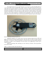
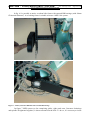
Figure 5 - Bloccaggio pedivella destra su perno centrale
To ensure a steady assembly between crank arm and spindle, it is necessary to insert the M6
hex socket cap screw into the lateral hollow in the crank arm (see fig. 5). Then the screw have to be
tightened (clockwise) till pre-set torque (see table 2). At this point the #3 M5 hex socket cap screws
(joining right crank arm to spider) must be firmly tightened as well (see table 1).
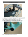
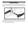
Once steps from Fig. 1 to 5 have been accomplished, MEP assembly can be mounted on the
bike. Bike’s look in BB shell zone with external BB bearings is shown in figure 6 below.
Figure 6 – Bike’s look in BB shell zone just before MEP set up in place