1
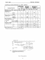
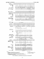
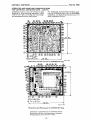
File No. 900 _ _ _ _ _ _ _ _ _ _ _ _ _ _ _ CDP1801, CDP1801C
Input-Output Byte Tr.nlfor
7 'N
(Note 3)
6 1 OUT 1 OUTPUT 1 M(R(X))+BUS;
R(X)+I;N=1
6 2 OUT2 OUTPUT 2 M(R(X))+BUS;
!HX)+I;N=2
6 3 OUT3 OUTPUT 3 M(R(X))+BUS;
R(X)+I;N=3
6 4 OUT 4 OUTPUT 4 M(R(X))+BUS;
R(X)+I;N=4
6 5 OUT5 OUTPUT 5 M(R(X))+BUS;
R(X)+I;N=5
6 6 OUT 6 OUTPUT 6 M(R(X))+BUS;
R(X)+I;N=6
6 7 OUT7 OUTPUT 7 M(R(X))+BUS;
R(X)+I;N=7
6 9 INP 1
INPUT 1
6 A INP 2
INPUT 2
6 B INP3
INPUT3
6 C INP4
INPUT 4
6 D INP5
INPUT 5
6 E INP 6
INPUT 6
6 F INP 7
INPUT 7
BUS+M(R(X));
N=9
BUS+M(R(X));
N=A
BUS+M(R(X));
N=B
BUS+M(R(X));
N=C
BUS+M(R(X));
N=D
BUS+M(R(X));
N=E
BUS+M(R (X));
N=F
Note 2: Th is type of abbreviated nomenclature is used when programs are designed with the aid of the COSMAC
Assembler Simulator/Debugger System, which is available on commercial timesharing systems. Refer
to "Program Development Guide for
the COSMAC Microprocessor", MPM102, for details.
Note 3: When executing any of the 69 to 6F
instructions, the contents of the D
register may be altered.
Test and Branch
The Test and Branch instructions can branch
unconditionally, test for D=O or D=I, test
for DF=O or DF=I, or can test the status of
the four I/O flags. A "successful" branch
loads the byte following the instruction into
the lower-order byte position of the current
program counter, effecting a branch within
the current 256-byte "page" of memory. If
the test to branch is not successful, the next
instruction in sequence is executed.
SIGNAL DESCRIPTION
Function
Signal
A single negative pulse is required. A momentary low on this line
places COSMAC in a repeating IDLE cycle"'with P = 0, R(O) =
0000 and IE = 1 (interrupt request allowed).
CLOCK
Single-phase clock. A typical clock frequency is 2 MHz at
VDD = 10 V. The clock is counted down internally to 8
clock pulses per machine cycle.
MAO to MA7
(8 Memory Address Lines)
The most significant 8 bits of the memory address is multiplexed
out first on these lines and held in a latch in the memory system
that is set by TPA. The 8 least significant bits are then multiplexed out on the same lines. The memory system always sees
a 16-bit address within one memory-addressing cycle.
MWR (Write Pulse)
A positive pulse appearing in a memory-write cycle, after the
address lines have settled down.
M READ (Read Level)
A low level on M READ indicates a memory read cycle. It
can be used to control three-state outputs from the addressed
memory which may have a common data input and output
bus. If a memory does not have a three-state high-impedance
output, M READ is useful for driving memory/bus separator
gates.
'" A repeating IDLE cycle represents an instruction halt. The processor will remain in this halt
state until an I/O Request (INTERRUPT, DMA-IN, or DMA-OUT) is activated. When this
request occurs, the IDLE cycle is terminated and the I/O request is serviced, and then the normal program is resumed. If a DMA request is used to bring the processor out of IDLE, it will
increment the contents of R(O) by 1. The first instruction will, therefore, be fetched from
memory location 0001 and not 0000. Thus, program execution begins at location 0001 with
R(O) as the program counter. It is recommended that MEM.LOC.OOOO not be used by the program.
- 12-