1
D3PLOT
User manual Version 11.0, March 2013
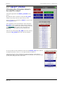
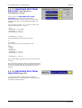
Res/Constraints Displaying nodal Restraints and Constraints
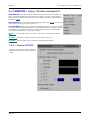
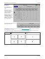
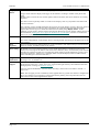
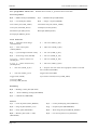
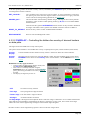
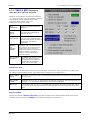
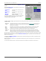
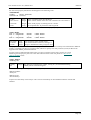
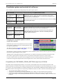
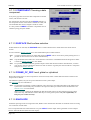
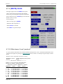
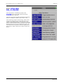
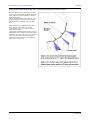
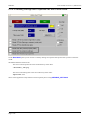
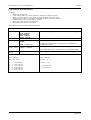
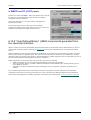
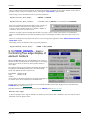
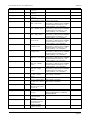
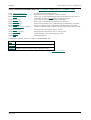
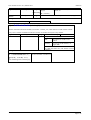
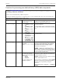
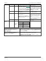
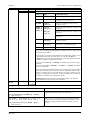
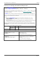
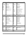
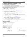
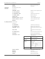
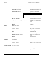
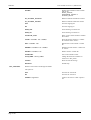
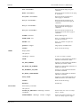
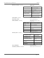
If a ZTF file is present, then restraint and constraint data will be available for any combination of nodes on:
*BOUNDARY
_SPC
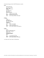
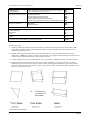
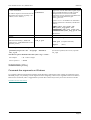
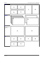
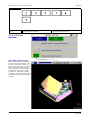
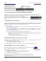
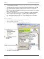
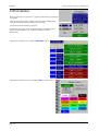
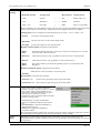
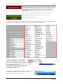
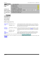
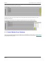
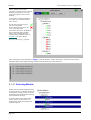
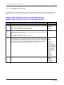
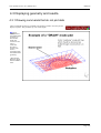
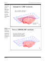
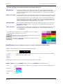
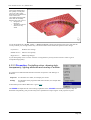
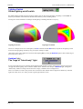
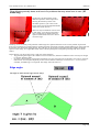
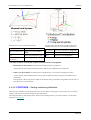
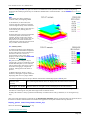
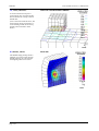
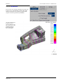
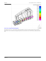
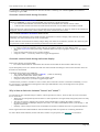
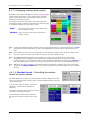
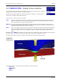
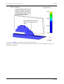
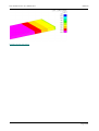
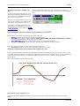
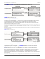
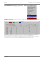
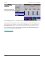
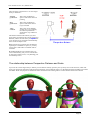
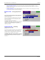
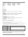
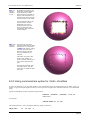
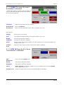
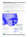
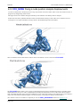
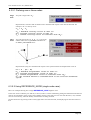
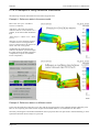
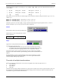
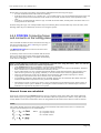
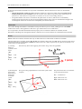
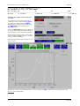
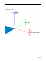
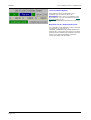
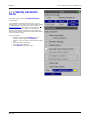
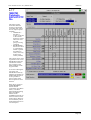
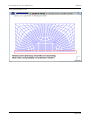
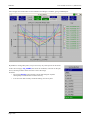
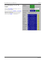
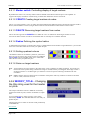
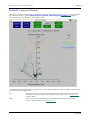
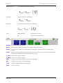
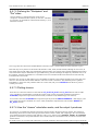
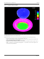
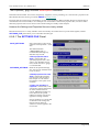
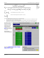
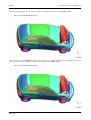
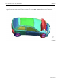
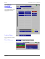
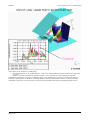
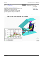
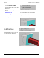
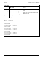
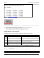
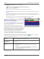
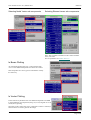
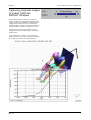
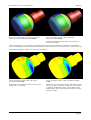
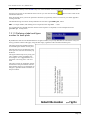
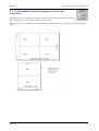
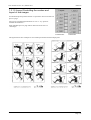
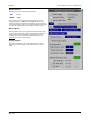
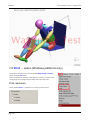
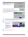
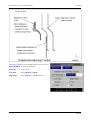
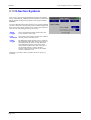
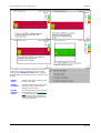
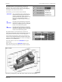
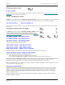
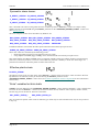
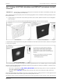
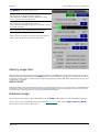
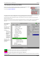
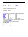
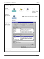
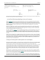
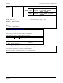
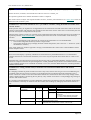
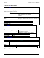
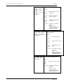
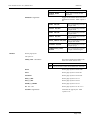
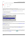
The image below shows how symbols for translational and
rotational restraints and constraints are displayed.
_PRESCRIBED_MOTION
_CYCLIC
_SLIDING
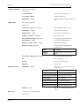
*CONTACT
_CONSTRAINED_xxx
_TIED_xxx
*CONSTRAINED _LINEAR
_WELD_xxx
_NODE_SET
_NODAL_RIGID_BODY
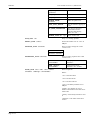
*PART
Page 6.68
which is rigid
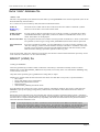
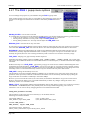
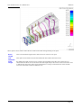
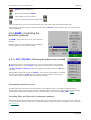
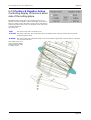
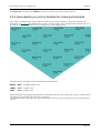
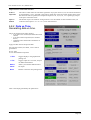
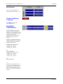
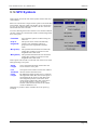
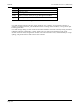
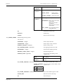
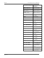
X direction : Red
Y direction : Green
Z direction : Blue
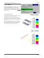
Translational restraints have a cross at their end
Rotational restraints have a box at their end.
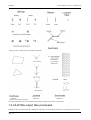
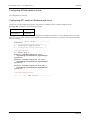
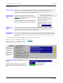
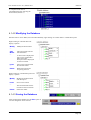
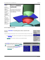
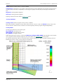
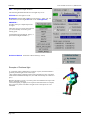
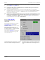
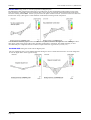
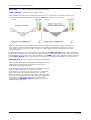
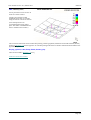
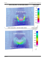
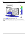
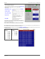
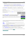
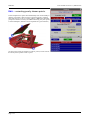
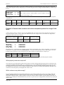
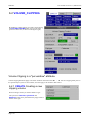
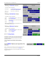
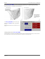
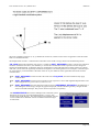
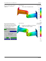
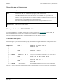
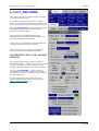
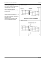
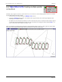
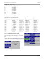
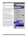
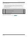
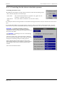
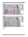
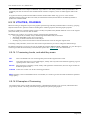
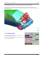
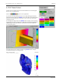
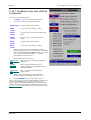
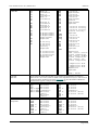
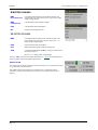
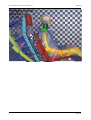
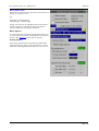
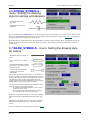
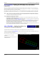
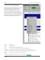
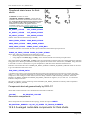
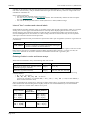
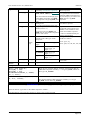
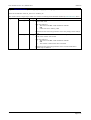
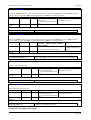
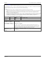
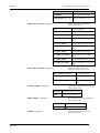
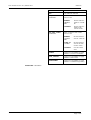
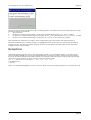
Turning on "labels" for the relevant item will give a brief
description of the source of the re/constraint.
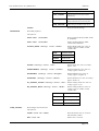
"T" designates translational restraint
"R" designates rotational restraint
"All" designates both translational and rotational