1
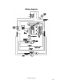
SHO1 SHO1-2 Hybridization Oven Installation, Operation, and Maintenance Guide Previously Designated As Models 1013 1013-2 Sheldon Manufacturing Inc. P.O. Box 627 Cornelius, Oregon 97113 EMAIL: [email protected] INTERNET: http://www.Shellab.com/~Shellab 1-800-322-4897 (503) 640-3000 FAX (503) 640-1366 4861629 01-07 Safety Notices A CAUTION notice denotes a hazard. It calls attention to an operating procedure, practice, or the like that, if not correctly performed or adhered to, could result in damage to the product or loss of important data. Do not proceed beyond a CAUTION notice until the indicated conditions are fully understood and met. A WARNING notice denotes a hazard. It calls attention to an operating procedure, practice, or the like that, if not correctly performed or adhered to, could result in personal injury or death. Do not proceed beyond a WARNING notice until the indicated conditions are fully understood and met. 2 TABLE OF CONTENTS Safety and Regulatory Information ................................................ 4 Technical and Environmental Specifications.................................................................. 5 Symbols........................................................................................................................... 5 Fuses and Battery ............................................................................................................ 5 Cleaning .......................................................................................................................... 5 Recycling the Product ..................................................................................................... 5 Installation ....................................................................................... 6 Prepare the Site ............................................................................................................... 6 Power source ................................................................................................................... 6 Environment .................................................................................................................... 6 Location .......................................................................................................................... 6 Inspect the Shipment ....................................................................................................... 7 Inspection ........................................................................................................................ 7 Ship kit contents.............................................................................................................. 7 Return shipment process ............................................................................................. 8 Unpack and Place the Oven ............................................................................................ 8 Install the Oven ............................................................................................................... 8 Install the leveling feet ................................................................................................ 8 Install the drip tray ...................................................................................................... 8 Install the rotator ......................................................................................................... 9 Clean the oven............................................................................................................. 9 Install the power cord.................................................................................................. 9 Operation ....................................................................................... 10 Control Panel Interface ................................................................................................. 10 Operating the Hybridization Oven ................................................................................ 11 To set a temperature .................................................................................................. 11 To load or unload the hybridization chamber ........................................................... 11 To calibrate the oven ................................................................................................. 12 Maintenance and Troubleshooting .............................................. 13 Cleaning .................................................................................................................... 13 Storage ...................................................................................................................... 13 Electrical components ............................................................................................... 13 Replacing the inline power fuse ................................................................................ 14 Troubleshooting ........................................................................................................ 15 Unit Specifications ........................................................................ 17 Net weight ................................................................................................................. 17 Interior dimensions ................................................................................................... 17 Temperature .............................................................................................................. 17 Rotation Speed .......................................................................................................... 17 Wiring Diagram ........................................................................................................ 18 3 1 Section Safety and Regulatory Information Intended Use This unit is for professional, industrial, or educational use, where the preparation or testing of materials is done at approximately atmospheric pressure and no flammable, volatile, or combustible materials are being heated. This unit is not intended for hazardous or household use. Important Safety Warnings There are several important safety notices that you should always keep in mind when using the Hybridization Oven. Many internal parts of the instrument carry dangerous voltages If the oven is connected to a power source, even if the power switch is off, potentially dangerous voltages exist on: • the wiring between the oven power cord and the AC power supply • the AC power supply itself • the wiring from the AC power supply to the power switch With the power switch on, potentially dangerous voltages also exist on: • all electronics boards in the oven • the internal wires and cables connected to these boards All these parts are shielded by covers. With the covers in place, it should be difficult to accidentally make contact with dangerous voltages. Unless specifically instructed to, never remove a cover. If the power cord insulation is frayed or worn, the cord must be replaced. Contact your customer service representative. Safety and Regulatory Information 4 Technical and Environmental Specifications Below are the oven’s technical and environmental specifications. • Class 1 equipment • Pollution degree 2 • Installation Category II • Indoor use only in ordinary atmospheres • Operating ambient temperatures between 15 °C and 35 °C • Relative humidity between 15 % to 85 % • Altitude not to exceed 2000 m operating • G2545A is rated for mains connection to 100–120 VAC or 220–240 VAC, 50/60 Hz, 6A, with main supply voltage fluctuations up to ±10% of the nominal voltage Symbols Warnings in the manual or on the oven must be observed during all phases of operation, service, and repair of this oven. Failure to comply with these precautions violates safety standards of design and the intended use of the oven. Sheldon Manufacturing, Inc. assumes no liability for the customer’s failure to comply with these requirements. See accompanying instructions for further description or discussion of a control or user item. Indicates a hot surface. Indicates earth (ground) terminal. Indicates potential shock hazard behind this partition. Fuses and Battery The oven uses one 5 × 20 mm fuse, 6.3 A, 250 V, type T. This fuse is located at the rear of the oven, above the power cord receptacle. Cleaning See “Cleaning” on page 14. Recycling the Product For recycling, contact your local sales office. Safety and Regulatory Information 5 2 Section Installation Prepare the Site Local city, county or other ordinances may govern the use of this equipment. If you have any questions about local requirements, please contact the appropriate local agency. The end user may perform installation, as it is unnecessary for this unit to be installed by a technician. Power source The electrical supply circuit to the oven must conform to all national and local electrical codes. Consult the oven's serial data plate (located on the top back panel of the oven) for the voltage, cycle wattage, and ampere requirements before connecting to power. A separate circuit is recommended to prevent possible loss of product due to overloading or failure of other equipment on the same circuit. The supply voltage should not vary by more than 10%. Environment Under normal circumstances, this unit is intended for use indoors at room temperatures between 15 °C and 35 °C, and relative humidity between 15%–85%. Contact Customer Service if operating in conditions outside of these limits. Location In selecting a location, consider all conditions that might affect performance, such as heat from radiators, ovens, autoclaves, etc. Avoid direct sun, fast moving air currents, heating/cooling ducts, and high-traffic areas. Allow a minimum of 5 cm (2.0 in) between the unit and walls or partitions, as they may obstruct free air flow. Please read this manual before attempting to install the oven. Installation 6 Inspect the Shipment Your satisfaction and safety require a complete understanding of this unit. Read the instructions thoroughly and be sure all operators are given adequate training before attempting to put the unit in service. Inspection The carrier, when accepting shipment, also accepts responsibility for safe delivery and is liable for loss or damage. On delivery, inspect for visible exterior damage, note and describe on the freight bill any damage found, and enter your claim on the form supplied by the carrier. Inspect for concealed loss or damage on the unit, both interior and exterior. If necessary, the carrier will arrange for official inspection to substantiate your claim. Verify that all of the equipment indicated on the packing slip is included with the unit. Carefully check all packaging before discarding. Ship kit contents Each oven unit comes with the following items that need to be installed (See Figure 1) A power cord set (depending on the voltage at the country of origin) Drip tray Four adjustable feet Brass locking pin The rotator (it is also called the “rotisserie,” part number 9670511) is included with the 1013 model. This equipment must be used only for its intended application; any alterations or modifications will void your warranty. Installation 7 Return shipment process Save the shipping crate for future use. The shipping crate will be used to ship the oven back to the factory for repair, if needed. If for any reason you must return the unit, please contact Customer Service Representative for authorization. Please have the model number and serial number available when calling the Customer Service Representative. Fill out the Environment Health and Safety (EH&S) form completely and attach it to the oven before shipping. Unpack and Place the Oven Before lifting/handling the 1013, note: This unit weighs 75.0 lbs. (34.0 kg) and should not be lifted from the ground to the bench by one person. Multiple persons or an appropriate lifting device that is sufficiently rated for these loads should be used. Units should only be lifted from their bottom surfaces. Doors, handles and knobs are not adequate for lifting or stabilization. The unit should be completely restrained from tipping during lifting or transport. Loose parts, such as drip trays, should be removed. Doors need to be positively locked in the closed position during transfer to prevent shifting and damage. Install the Oven Install the leveling feet For the 1013 Hybridization Oven to operate properly, the unit must sit level and on a solid foundation. To ensure that the instrument is level: 1. Install the supplied leveling feet in the four holes located in the bottom corners of the unit by screwing them in. 2. Adjust the foot at each corner until the unit stands level and solid without rocking. Install the drip tray Install the drip tray on the bottom of the oven. Make sure the oven door can close once the tray is installed. If the unit must be moved, turn the leveling feet all the way clockwise to prevent damage while moving. Installation 8 Install the rotator The rotator (also called rotisserie, Sheldon part number 9670511; see Figure 5) comes with your 1013 oven. To install the rotator into the oven: 1. Set the AC power switch to OFF. 2. Open the oven. Locate the rotator drive shaft coupling on the left side oven wall and the rotator shaft support bushing on the right side oven wall. See Figure 2. 3. Move the rotator into the oven and insert the two pins on the rotator drive shaft coupling into the two holes on the rotator coupling. See Figure 3. 4. While holding the rotator to keep the drive coupling attached, lower the rotator shaft into the slot in the rotator shaft support bushing. See Figure 4. 5. Complete rotator installation by inserting the brass locking pin through the two holes in the shaft support bushing. See Figure 5. Rotator drive shaft coupling with two pins Rotator shaft support bushing Figure 2 Rotator shaft attachment locations Figure 3 Attaching the rotator to the drive shaft coupling Holes for brass locking pin Figure 4 Inserting the rotator shaft into the rotator shaft support bushing Figure 5 Rotator correctly installed Clean the oven Before first use, clean the oven as described in “Cleaning” on page 14. Install the power cord The correct power cord that is appropriate for your country will ship with the unit. Use of an inappropriate power cord may damage your oven or pose a safety hazard. Installation 9 3 Section Operation Control Panel Interface The 1013 Hybridization Oven is operated using the control panel interface (see Figure 6), which is located on the front of the oven. Rotational speed control Use to set the rotator speed from 2 to 20 rpm. Turning the knob clockwise increases the rotator speed. Set to 0 (zero) to turn off the rotator. Heating indicator Lights continuously when the oven is heating. Blinks when the oven is at or near its set point. Temperature display Displays the current oven temperature in degrees centigrade (°C). Temperature controls Use the up and down arrow keys to adjust the oven temperature set point. JOG switch Press and hold ON to turn the rotator, for example, when loading the oven. When released, the rotator stops. The rotational speed control knob cannot be set at zero for the JOG switch to operate properly. Operation 10 Operating the Hybridization Oven To set a temperature Using the temperature controller: 1. Enter set point mode by pressing either or The digital display will start to blink. While blinking, the digital display shows the current set point. 2. Press or to enter the desired set point temperature. If the arrow pads are not pressed for five (5) seconds, the display will stop blinking and will read the temperature in the chamber. To load or unload the hybridization chamber Load the samples into the oven as follows: 1. Open the oven door. If the rotator is in motion, it will stop moving once the oven door is opened. 2. Use the JOG switch to move the rotator to the desired chamber load/unload position. The rotator speed should be at least 2. 3. Load or unload the hybridization chambers. To load the bottles into the rotator, press the bottles into the upper and lower clips until locked in place. See picture below. 4. Use the JOG switch to move the rotator to the next rack, and continue loading/unloading the bottles. After loading/unloading all bottles, close the oven door. For stable control, the set point must be a minimum of 5 degrees above ambient. The oven and rotator may be hot. Before handling, lower the oven temperature to <35 °C and allow it to cool, or wear heat-resistant gloves. When loading samples onto the rotator, be sure to balance the load between the racks. Also take care in balancing the loads horizontally on the racks themselves. Operation 11 To calibrate the oven Calibrate the oven: • After first installation in a working environment. • After each 3 months of use To calibrate the oven: 1. Install the rotator and load it with a typical number of chambers. 2. Turn on the oven and set to a typical operating temperature. 3. Allow the oven to stabilize for at least 1 hour. 4. Place a certified reference thermometer in the chamber near the sample area. 5. Allow the temperature to stabilize again until the thermometer reads a constant value for one hour. 6. Compare the digital display on the control panel with the reference thermometer. 7. If there is a difference of more than 0.2 °C, put the display into calibration mode by pressing both and at the same time until the temperature display’s two outside decimal points begin to flash. 8. While the decimal points are flashing, press the or arrow pad until the display reads the correct value. Allow the oven to stabilize, and then recheck the temperature. Repeat step 5 through step 8, if necessary. Sheldon highly recommends recalibrating the oven temperature every three (3) months. To ensure correctness of temperature calibration, the rotator needs to be installed and loaded. Sheldon recommends using a digital thermometer for calibration. Operation 12 4 Section Maintenance and Troubleshooting Cleaning To clean the unit: 1. Remove the rotator and drip tray. 2. Clean the oven using mild detergent. 3. Clean the rotator and drip tray using either the same solution used for the chamber, or an autoclave. Storage If the unit is to be turned off for any length of time, assure that the chamber and drip tray are dry and store at room temperature. Failure to do this may cause the interior to become contaminated. No adjustment to controls should be required when restarting the unit. If the unit is shut down for transport, be sure to disconnect the power cord and turn the leveling feet in all the way. See Chapter 2, “Unpack and Place the Oven” for further instruction on preparing the oven for transportation. Electrical components There is no maintenance necessary on electrical components. If the unit fails to operate as specified, review “Troubleshooting” on page 16 before calling for service. Prior to any maintenance or service on this unit, disconnect the power cord from the oven. The oven interior surface should be cleaned once a month. Do not use chlorine-based bleach or abrasives, as this will damage the chamber interior. Maintenance and Troubleshooting 13 Replacing the inline power fuse The unit is protected by an inline fuse located behind the power cord. If needed, replace the fuse as described below: 1. Turn off the oven and rotator, then disconnect from the power source. 2. Remove the power cord from the back of the oven. 3. Using a small, flat-bladed screwdriver pry the fuse holder from the back of the unit. See Figure 8. 4. Inspect the fuse in service. See Figure 9. Replace if blown with a 6.3 A, 250 V type T fuse. If the inline power fuse blows repeatedly, check for the reason why. Check that the oven is the correct voltage type, check the power cord, and check the power supply. Maintenance and Troubleshooting 14 Troubleshooting The following table shows a list of problems and their corresponding solutions. If these instructions do not correct the problem, call Customer Service for further assistance. Table 1 Problems and solutions Problem Action The unit will not turn on. 1 Verify that the power cord is plugged into the oven and power source. 2 Verify that the power switch is ON. 3 Check the fuse as described in “Replacing the inline power fuse” on page 15 and replace if blown. 1 The controller might be set too high. To set the oven temperature, see “To set a temperature” on page 12. 1 Check if the set temperature is below the room temperature. 2 Turn the unit OFF. Wait for five seconds and then turn it on to see if the error message disappears. Temperature is too high. Display reads “HI”. Chamber temperature overshoots the set point and then settles to the set point. Temperature is too low. Display reads “LO”. The unit will not heat over a temperature that is below the set point. The unit will not heat up at all. For hybridization units, ±1 ° of set point may be normal. To recalibrate the oven, see “To calibrate the oven” on page 13. 1 The controller might be set too low. To set the oven temperature, see “To set a temperature” on page 12 for information on setting the oven temperature. 2 The unit may not have recovered from opening the door; wait for the display to stabilize. 3 The unit may not have recovered from a power failure or from being turned off. Ovens usually will need two hours to warm up and stabilize. The ambient temperature might be below the temperature range of the unit. Refer to “Technical and Environmental Specifications” on page 6. 1 Confirm that the fan is moving. Check fan motor motion and feel for air movement in chamber. 2 Confirm that the supply amperage and voltage match the data plate. 3 To calibrate the oven, see “To calibrate the oven” on page 13. Make sure that the circuit breaker and fuse have not blown and are still operating correctly. Maintenance and Troubleshooting 15 Table 1 Problems and solutions (continued) Problem Action The indicated chamber temperature is unstable. Temperature range ±1 °C is normal. 1 Check to make sure the fan is working by checking the fan motor motion and feeling for air movement in the chamber. Verify movement of the cooling fan in the back of chamber. 2 Doors opening, air flow from heaters, and air flow from air conditioner units may radically change the ambient room temperature. Stabilize ambient conditions. Assure that the oven set point is at least 5 °C above the ambient room temperature. 3 See if the ambient room temperature is fluctuating. 4 Verify that the unit is not affected by another temperature source, such as direct sunlight or direct air conditioning to the unit. There may be a calibration error. To recalibrate the oven, see “To calibrate the oven” on page 13. Allow two hours for the temperature to stabilize. Turn the entire unit OFF and then ON to reset. Display and reference thermometer do not match. The set point or calibration cannot be adjusted. The oven is calibrated at one temperature, but not at another. Black soot might appear on the oven floor and walls. This can be a normal condition when the operating temperature varies widely. For maximum accuracy, calibration should be done at or as close as possible to the operating temperature in use. Clean the interior oven as specified on page 14. Maintenance and Troubleshooting 16 5 Section Unit Specifications Net weight Unloaded unit weight, without rotator: 75.0 lbs (34.0 kg) Interior dimensions 12.5 in wide x 12 in deep x 14.5 in high (31.8 cm x 30.5 cm x 36.8 cm) Temperature Operating temperature range: Amb. +5 °C to 70 °C Precision: 0.1 °C Rotation Speed 20 mph Unit Specifications 17 Wiring Diagram Unit Specifications 18