1
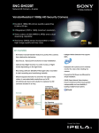
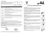
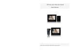
AMC 1080P/1080i HD PTZ Color Video Cameras User Manual V1.1 www.ismart-video.com SAFETY NOTICE-IMPORTANT!!! The following important notes must be followed carefully to run the camera and respective accessories in total safety. The camera and relative accessories are called video system in this section. Before installing the camera, please read this manual carefully. Please follow installation instructions indicated in this manual during installation. Please keep this manual for future use. The installation should be performed by qualified service personnel or system installers in accordance with all local rules. Before powering on the camera, please check the power voltage carefully. Make sure that you are using the correct power source. Please put the power cable, video cable and control cable in safe place. Do not operate the camera beyond the specified temperature and humidity. Working temperature range of the camera is between 0℃ and +40℃. The ambient humidity range is less than 95﹪. During transporting, avoid violent shake or force to the camera. To prevent electric shock, do not remove screws or housing of the camera. There are no self-serviceable parts inside. Refer to qualified service personnel for servicing. Video cable and RS485 cable should be kept far away from other cables. Shielded and independent wiring is necessary for video and control cables. Never aim the lens of the camera at the sun or other extremely bright objects. Otherwise, it may cause damage. When cleaning the camera, please use soft cloth. If the camera is very dirty, wipe it off gently with a soft cloth moistened with a weak solution of water and a neutral kitchen detergent. Wring all liquid from the cloth before wiping the camera, then wipe off all remaining dirt with a soft, dry cloth. Use lens cleaning paper to clean the lens. Do not move the camera head manually. In doing so would result in malfunction of the camera. Do not hold the camera head when carrying the video camera. This camera is for indoor use only. It is not designed for outdoor use. Make sure the camera is not directly exposed to rain and water. Make sure the camera is far away from area where radiation, X-rays, strong electric waves, or magnetism is generated. CONTENTS ABOUT THE PRODUCT -------------------------------------------------------- 1 FEATURES -------------------------------------------------------------------------------- 1 LIST OF PARTS & ACCESSORIES ----------------------------------------------------------- 1 MAIN PARTS & INTERFACES ---------------------------------------------------------------- 2 DIP SWITCHES SETTINGS ------------------------------------------------------------------ 3 REMOTE CONTROLLER -------------------------------------------------------------------- 4 CABLE CONNECTING INSTRUCTIONS --------------------------------------- 6 DVI-I INTERFACE -------------------------------------------------------------------------- 6 CABLE PACKAGE -------------------------------------------------------------------------- 7 HD-SDI INTERFACE ----------------------------------------------------------------------- 7 POWER CONNECTION---------------------------------------------------------------------- 8 REMOTE CONTROLLER OPERATION ----------------------------------------- 9 POWER ----------------------------------------------------------------------------------- 9 HOME ------------------------------------------------------------------------------------ 9 CAMERA SELECTION ----------------------------------------------------------------------- 9 FOCUS ----------------------------------------------------------------------------------- 9 PATTERN -------------------------------------------------------------------------------- 10 IRIS-------------------------------------------------------------------------------------- 10 BLC ------------------------------------------------------------------------------------- 10 ZOOM ----------------------------------------------------------------------------------- 10 MENU ----------------------------------------------------------------------------------- 10 BACK ------------------------------------------------------------------------------------ 11 DIRECTION / MENU OPERATION ----------------------------------------------------------- 11 OK -------------------------------------------------------------------------------------- 11 DATA ------------------------------------------------------------------------------------ 11 PRESET SETTING ------------------------------------------------------------------------- 12 NUMBER KEYS --------------------------------------------------------------------------- 12 CANCEL --------------------------------------------------------------------------------- 12 ENTER ----------------------------------------------------------------------------------- 12 LIST OF SPECIAL PRESET COMMANDS ----------------------------------------------------- 12 INSTALLATION INSTRUCTIONS--------------------------------------------- 13 DESKTOP MOUNT INSTALLATION ---------------------------------------------------------- 13 WALL MOUNT INSTALLATION -------------------------------------------------------------- 13 CEILING MOUNT INSTALLATION ------------------------------------------------------------ 14 PENDANT MOUNT INSTALLATION ---------------------------------------------------------- 15 MENU SETTINGS ------------------------------------------------------------ 16 MENU CONFIGURATION ------------------------------------------------------------------- 16 MENU EXPLANATION---------------------------------------------------------------------- 20 VIDEO ---------------------------------------------------------------------------------- 21 EXPOSURE ---------------------------------------------------------------------------- 21 WHITE BALANCE ----------------------------------------------------------------------- 22 PAN/TILT/ZOOM ------------------------------------------------------------------------ 22 SYSTEM -------------------------------------------------------------------------------- 23 RESTORE DEFAULTS ------------------------------------------------------------------ 23 ANNEX 1 TECHNICAL SPECIFICATIONS ------------------------------------ 24 ANNEX 2 SIZE AND DIMENSION -------------------------------------------- 26 ANNEX 3 SW1 DEFINITION -------------------------------------------------- 27 TROUBLESHOOTING -------------------------------------------------------- 29 ABOUT THE PRODUCT List Of Parts & Accessories When you open the box, check all accessories according to the packing list. ABOUT THE PRODUCT Features Camera (1) 1/2.8 inch Exmor CMOS sensor, 3.27megapixel; Supports full resolution up to1080/60P and SD video formats; Simultaneous outputs of HD and SD videos; HD video interfaces: HD-SDI, DVI-I; OSD menu; Power Adapter (1) 20x optical zoom, 12x digital zoom; Precise driving system with high reliability and precision; Support VISCA , Daisy chain and Pelco protocols; With IR remote controller; Smart AE technology to effectively avoid Remote Controller (1) the interference of complicated lights from projectors ,monitors etc; Desktop/Ceiling/ Wall/Pendant mount optional. Cable Package (1) 1 Main Parts & Interfaces Bottom View Camera Front View 8DIP Switch Set camera address, protocol, baud rate, 1Camera Module video format and mounting type. 2Power Indicator 3Remote Controller Indicator 9 Mounting Hole 1/4”inch screw thread for fixing camera. Rear View 10 Locating Hole To defineinstallation direction of camera. 11 Fixing Screw Hole (M3) To connect the camera with pendant mounting bracket. 4 DVI-I interface 5 HD-SDI interface 6 Composite interfaces(CVBS output, RS48/RS422, RS232 in and RS232 out) 7 DC12V power input 2 DIPSwitches Settings is used to set video output format. Refer to below chart for details: Before operating the camera, set the camera address, DVI-I output signal format and video has two DIP switches: SW1 and SW2 as below: Note SW1 is used to set address, video output and mounting type, SW2 is used to set protocol, baud rate and video format. Default Settings Address Baud Rate Protocol Video Format Analog Video Format Mounting Type 1 9600bps VISCA 1080i50 YPbPr Desktop Installation 1 OFF ON Protocol OFF ON DIP No. 3 OFF ON Baud Rate(bps) OFF ON DIP No. 5 OFF ON OFF ON OFF Video Format ON OFF ON OFF ON SW2 2 OFF OFF ON ON 4 OFF OFF ON ON 6 7 OFF OFF OFF OFF ON OFF ON OFF OFF ON OFF ON ON ON ON ON OFF OFF OFF OFF VISCA PELCO- D PELCO- P Reserved 2400 4800 9600 38400 8 OFF 1080P60 OFF 1080P50 OFF 1080i60 OFF 1080i50 OFF 720P60 OFF 720P50 OFF 1080P30 OFF 1080P25 ON 720P30 ON 720P25 When HD video output format is set as 1080p60,1080i60 or 720p60, relative SD video format is NTSC; when HD video output format is set as 1080p50, 1080i50 or 720p50, Sw1 settings relative SD video format is PAL. No 1~6 are used to set address for camera, the DIPs adopt binary system. No. 7 is used to set analog video format. No. 8 is used to set mounting type. Refer to page 27 for details. Sw2 settings No. 1 and 2 of SW2 is used to set protocol; no. 3 and 4 is used to set baud rate; no. 5, 6, 7, 8 3 ABOUT THE PRODUCT format etc through DIP switches. The camera DIP No. Remote Controller 2 Camera Selection Button Used to switch among 4 cameras, press 1-4 number buttons to control cameras with 1-4 addresses respectively. For example, press button 1 to control the camera with address 1. 3 Focus Press“AUTO”button to switch to Auto Focus, press “MANU” button to switch to Manual Focus mode. “ ”button to Focus Near “ ”button to Focus Far “ ”button to Auto Focus once every time it is pressed, then switch back to Manual Focus mode. 4 Iris Press“ ”button to reset iris value to default.“ ”button to Iris Open “ ”button to Iris Close. 5 Menu PressMENUbutton to enter / exit menu. 6 Data PressDATAbutton to set on / off the display 1 HOME Press HOMEbutton, camera moves to initial position where both pan and tilt angle is zero. of pan tilt angel, zoom times and other prompt message. 7 Number Keys Used to input numbers, for example, preset number. 4 16Direction / Menu Operation 8 Cancel To cancel numbers input In None-menu status, press these four buttonsto pan left/right and tilt up/down. 9Power power source, in none-menu status, press this button to turn on / off the camera. 10 Reserved buttons(F1, F2, F3, F4) These buttons are reserved for future use. In Menu status: or button to select among menu options, or ABOUT THE PRODUCT After the camera has been connected to to change option / value. 17Preset Setting “ ”button to call a preset. Input number key(s), and then press this 11Pattern button to call a preset. Used to activate Pattern Scan1 and Pattern “ Scan2. ”button to set a preset. Move the camera to a specific position, 12 BLC adjust focus value and etc, and then press Used to open / close back light this button to set a preset. compensation. “ 13 Zoom ”button to clear a preset. Input number key(s), and then press this Used to adjust zooming times. “ ”button to zoom in “ ”button to zoom out. button to clear a preset. 18Enter 14 Back Press“ After inputting numbers, press this button to confirm. ”button to go back to previous menu. 15OK In None-menu status: press this button to switch among pan / tilt control speeds. In Menu status: get into relative menu option after it has been selected. 5 CABLE CONNECTING INSTRUCTIONS Connect the camera to relative devices with the cables supplied with the camera. DVI-I Interface 6 Cable Package HD-SDI Interface CABLE CONNECTING INSTRUCTIONS Note Once the RS-422/RS-485 interface is used as RS485 control, simply connect R+ & T+ as RS485+ and R- & T- as RS485-. 7 Power Connection Once camera started successfully, in None-menu status, the Power button 1. Connect power adapter supplied together with the camera to power source, after powered on, camera’s power indicator lightsup, the camera will start self-testing, afterfinished, camera moves to Home position. Note If preset 0 has been saved, after powered on, camera moves to preset 0 automatically; if preset 0 has not been saved, after powered on, camera moves to Home position, where both pan and tilt angle is zero and zooming time is 1x. 2. Use remote control to turn on / off camera 8 can be used to turn on /off the camera. REMOTE CONTROLLER Camera Selection OPERATION REMOTE CONTROLLER OPERATION Before operating the camera, check if power and other devices have been correctly connected. Used to switch among 4 cameras, press 1-4 number buttons to control cameras with 1-4 Power addresses respectively. For example, press button 1 to control the camera with address 1. Default address of camera is 1, the remote controller supports to control camera with address 0 or 5~63. Focus In none-menu status, press this button to turn on / off the camera. Home Press“AUTO”button to switch to Auto Focus, press “MANU” button to switch to Manual Focus mode. Press HOME button, camera moves to initial “ ”button to Focus Near “ ”button to Focus Far position where both pan and tilt angle is zero. 9 “ ”button to Auto Focus once every time it BLC is pressed, then switch back to Manual Focus mode. Pattern Used to open / close back light compensation. Zoom Used to activate Pattern Scan1 and Pattern Scan2. Pattern Scan 1: camera pans between±45°of current position. Pattern Scan 2: camera pans between ±90° of current position. Used to adjust zooming times. Iris “ ”button to zoom in “ ”button to zoom out. Menu Press“ 10 ”button to reset iris value to default. “ ”button to Iris Open “ ”button to Iris Close. Press MENU button to enter /exit menu. Menu operation Back among menu options, In Menu status: or button to select or to change REMOTE CONTROLLER OPERATION option / value. OK Press“ ”button to go back to previous menu. Direction / Menu Operation In None-menu status: press this button to switch among pan / tilt control speeds. In Menu status: get into relative menu option after it has been selected. Data Direction In None-menu status, press these four buttons to pan left/right and tilt up/down. Fast and frequently press button to realize fast control; press and hold the button to realize slow control. Press DATAbutton to set on / off the display of pan tilt angel, zoom times and other prompt message. 11 Preset Setting Cancel “ To cancel numbers input. ”button to call a preset. Numbers input key(s), and then press this button to call a preset. “ Enter ”button to set a preset. Move the camera to a specific position, adjust focus value and etc, and then press this button to set a preset. “ ”button to clear a preset. Input number key(s), and then press this button to clear a preset. After inputting number(s), press this button to confirm. Number Keys List of Special Preset Commands Preset No. 93 95 96 Used to input numbers. 12 Function Cruise, camera switches among saved 0~29 presets repeatedly and sequentially in fixed interval. Get into menu Delete all presets Note INSTALLATION INSTRUCTIONS INSTALLATION INSTRUCTIONS Take effective measures to avoid camera from dropping. Do not grab the camera head when carrying. Do not rotate the camera head with hand. It may cause malfunction to the camera. The camera has 4 installation types: desktop, ceiling, wall, pendant mount installations. Wall Mount Installation Note Before installing, make sure there is enough space to install the camera and its parts. Make sure the installed place is strong and safe enough to hold the camera and relative parts, it is suggested that the installed place can withstand 4 times the weight of the camera and its relative parts. Desktop Mount Installation 1. According to diameter and position of the 4 installation holes (As shown below) on 1. Put the camera on a flat surface. In case the camera has to be placed on an inclined surface, make sure the cline the bracket, drill 4 holes on the wall and fix the bracket onto the wall by using 4 screws which should be prepared by you. angle is less than 15 degrees to ensure proper pan /tilt operation. 2. Before fixing the camera, set the DIP switches of the camera correctly. 13 3. Use inch screws to fix the camera on the 2. Fix the mounting plate onto the ceiling or bracket, fix the limit screw according to cement roof with 3 screws which should actual requirement, and make sure the be prepared by you. camera is tightly fixed onto the bracket before your hands leave the camera. 3. Before fixing the camera, set the DIP switches of the camera correctly. 4. Use 3 screws to fix the camera on the ceiling mount plate. Ceiling Mount Installation 5. Push forward camera's bottom slide according to the mounting plate’s bottom 1. According to diameter and position of the 3 installation hole (as shown below), drill 3 holes on the ceiling or cement roof correspondingly. 14 slide until they reach their limit. Fix the ceiling mount plate and camera’s bottom plate with M3×8 screws. Pendant Mount Installation INSTALLATION INSTRUCTIONS 3. Use 2 screws to fix the upper pole and lower pole. The length is adjustable ranging from 350mm~600mm. 1. According to diameter and position of the 4 holes on the pole (as shown below), drill 3 holes on the ceiling or cement roof. 4. Use screws to fix camera on the lower pole. Make sure the camera is tightly fixed 2. Fix the upper pole brackets onto the wall or cement roof tightly with 4 screws which onto the bracket before your hands leave the camera. are prepared by you. 15 MENU SETTINGS Menu Configuration <VIDEO> SHARPNESS 0, 1, 2, 3, 4, 5, 6, 7, 8, 9, 10, 11, 12, 13, 14, 15 BRIGHTNESS -5, -4, -3, -2, -1, 0, +1, +2, +3, +4, +5 CONTRAST -5, -4, -3, -2, -1, 0, +1, +2, +3, +4, +5 SATURATION -5, -4, -3, -2, -1, 0, +1, +2, +3, +4, +5 2DNR LEVEL OFF, LOW, MID, MAX 3DNR LEVEL OFF,LOW, MID, MAX WIDE DYNAMIC ON, AUTO, OFF Refer to Page21 16 <EXPOSURE> MODE FULL AUTO SLOW ON, OFF SHT.LIMIT Refer to Page21 GAIN -3, 0, +2, +4, +6, +8, +10, MENU SETTINGS MANUAL +12, +14, +16, +18, +20, +22, +24, +26, +28 SPEED 1/1, 1/2, 1/3, 1/6, 1/12, 1/25, 1/50, 1/75, 1/100, 1/120, 1/150, 1/215, 1/300, 1/425, 1/600, 1/1000, 1/1250, 1/1750, 1/2500, 1/3500, 1/6000, 1/10000 IRIS F14, F11, F9.6, F8, F6.8, F5.6, F4.8, F4, F3.4, F2.8, F2.4, F2, F1.6, CLOSE SHUTTER SPEED 1/1, 1/2, 1/3, 1/6, 1/12, 1/25, 1/50, 1/75, 1/100, PRI 1/120, 1/150, 1/215, 1/300, 1/425, 1/600, 1/1000, 1/1250, 1/1750, 1/2500, 1/3500, 1/6000, 1/10000 IRIS PRI IRIS F14, F11, F9.6, F8, F6.8, F5.6, F4.8, F4, F3.4, F2.8, F2.4, F2, F1.6, CLOSE BRIGHT PRI BRIGHT 0, 5, 6,7, 8, 9, 10, 11, 12, 13, 14, 15, 16, 17, 18, 19, 20, 21, 22, 23, 24, 25, 26, 27, 28, 29, 30, 31 EXP-COMP ON LEVEL -7, -6, -5, -4, -3, -2, -1, 0, +1, +2, +3, +4, +5, +6,+7 OFF BLC ON, OFF 17 <WHITE BALANCE> MODE Refer to Page22 AUTO ATW ONE PUSH INDOOR OUTDOOR MANUAL R.GAIN 0~255 B.GAIN 0~255 <PAN TILT ZOOM> PAN/TILT SPEED 1, 2, 3, 4, 5, 6, 7, 8 Refer to Page22 PAN/TILT LIMIT ON, OFF UP -30°~+90° DOWN -30°~+90° LEFT -170°~+170° RIGHT -170°~+170° D-ZOOM LIMIT X1, X2, X3, X4, X5, X6, X7, X8, X9, X10, X11, X12 PTZ TRIG AF ON, OFF POWER UP ACTION PRESET 1, PRESET 2, PRESET 3, PRESET 4, PRESET 5, PRESET 6, PRESET 7, PRESET 8, PRESET 9, HOME 18 ADDRESS Refer to PROTOCOL VISCA BAUDRATE 2400 Page23 1 MENU SETTINGS <SYSTEM> VIDEO FORMAT 720P50 DVI-I OUTPUT YPBPR MOUNT MODE STAND FIRMWARE VER V1.0.4 DISPLAY INFO ON, OFF <RESTORE DEFAULTS> Refer to Page23 19 Submenus Menu Explanation From main menu, navigate to select <EXPOSURE> menu, press OKto enter. Main Menu Press MENUbutton to enter / exit menu. ❶ <MENU> VIDEO EXPOSURE WHITE BALANCE PAN TILT ZOOM SYSTEM RESTORE DEFAULTS ❷ ❸ SELECT NEXT ❶❸<EXPOSURE> MODEMANUAL GAIN 0 ❷ SPEED 1/1 IRIS F14 EX-COMP LEVEL BLC ❹ EXIT SELECT ON 0 OFF BACK ❶ Menu Hint It displays currently selected menu option. ❶Menu Hint It displays currently selected menu option. ❷ Menu Options It displays options under current menu ❷Menu Options hint. It displays options under current menu hint. Press or button to select among menu options, once font of options turned Press or button to select among menu options, once font of options turned from white color to yellow color, it indicates from white color to yellow color, it indicates the menu has been elected, press OK button to get into this menu. the menu has been elected, press OKbutton to get into this menu. ❸Prompt Message “ SELECT”indicates it is possible to press or button to select menu Press or button to change value. ❹Prompt Message “ SELECT”indicates it is possible to options. press or “ press NEXT”indicates it is possible to to select menu options, or to change value press OKbutton to enter next level menu. “ BACK”indicates it is possible to press “ to return to previous menu. EXIT”indicates it is possible to press MENU button to exit menu. 20 ❸Manual Exposure VIDEO EXPOSURE VIDEO menu is used to change video value. EXPOSURE menu is used to adjust exposure SELECT value. +5 +2 -5 OFF OFF OFF BACK <EXPOSURE> MODEMANUAL GAIN 0 SPEED 1/1 IRIS F14 EXP-COMP LEVEL BLC SELECT MENU SETTINGS <VIDEO> SHARPNESS8 BRIGHTNESS CONTRAST SATURATION 2DNR LEVEL 3DNR LEVEL WIDE DYNAMIC ON 0 ON BACK Available Options: Available Options: SHARPNESS:0, 1, 2, 3, 4, 5, 6, 7, 8, 9, 10, 11, 12, 13, 14, 15. BRIGHTNESS:-5, -4, -3, -2, -1, 0, +1, +2, +3, +4, +5. CONTRAST:-5, -4, -3, -2, -1, 0, +1, +2, +3, +4, +5. MODE: FULL AUTO: Gain, Shutter Speed and Iris value are adjusted automatically accordingly to working environment. SLOW SHT. LIMIT:this option sits under “Full Auto”, there are On and Off options. SATURATION:-5, -4, -3, -2, -1, 0, +1, +2, +3, +4, +5. MANUAL:manually adjust Gain, Shutter Speed and Iris 2DNR LEVEL: OFF, LOW, MID, MAX GAIN: -3, 0, +2, +4, +6, +8, +10, +12, +14, If camera displays color image, it is suggested to turn off the 2DNR level, otherwise, the video trails will be generated. The higher the level is, the better is the noise reduction performance, but more +16, +18, +20, +22, +24, +26, +28. SPEED: 1/1, 1/2, 1/3, 1/6, 1/12, 1/25, 1/50, 1/75, 1/100, 1/120, 1/150, 1/215, 1/300, 1/425, 1/600, 1/1000, 1/1250, 1/1750, 1/2500, 1/3500, 1/6000, 1/10000s video trails will be generated. IRIS: F14, F11, F9.6, F8, F6.8, F5.6, F4.8, 3DNR LEVEL: OFF, LOW, MID, MAX. F4, F3.4, F2.8, F2.4, F2, F1.6, CLOSE. WIDE DYNAMIC: ON, AUTO, OFF 21 SHUTTER PRI:Gain and Iris value are WHITE BALANCE adjusted automatically according to working environment; shutter speed value is adjustable manually. SPEED:1/1, 1/2, 1/3, 1/6, 1/12, 1/25, 1/50, 1/75, 1/100, 1/120, 1/150, 1/215, 1/300, 1/425, 1/600, 1/1000, 1/1250, 1/1750, WHITE BALANCE menu is used to select from white balance modes. Available options: <WHITE BALANCE> MODE MANUAL R.GAIN 1 B.GAIN 128 1/2500, 1/3500, 1/6000, 1/10000s. SELECT BACK IRIS PRI:Gain and shutter speed value are adjusted automatically according to working environment; Iris value is adjustable MODE: AUTO, ATW(auto tracking), ONE PUSH, INDOOR, OUTDOOR, MANUAL. manually. “ONE PUSH”:when in “ONE PUSH IRIS: F14, F11, F9.6, F8, F6.8, F5.6, F4.8, F4, F3.4, F2.8, F2.4, F2, F1.6, CLOSE. BRIGHT PRI: manually adjust bright of image. TRIGGER” mode, aim the camera at a pure white object (say a white paper), then press OK button. BRIGHT: 0, 5, 6, 7, 8, 9, 10, 11, 12, 13, 14, “MANUAL”mode: R.GAIN and B. GAIN 15, 16, 17, 18, 19, 20, 21, 22, 23, 24, 25, 26, value can be chosen from 0~255. 27, 28, 29, 30, 31. EXP-COMP:onceEXP-COMP is set as On, below level options become available -7, -6, -5, -4, -3, -2, -1, 0, +1, +2, +3, +4, +5, +6, +7 PAN/TILT/ZOOM PAN/TILT/ZOOM is used to change pan/tilt/zoom value, available options: +7 is the maximumcompensation value for bright, -7 is the maximum compensation value for dark. BLC : ON, OFF Backlight compensation(BLC) is video gain done automatically to correct the exposure of subjects that are in front of a bright light source. 22 <PAN TILT ZOOM> PAN/TILT SPEED PAN/TILT LIMIT UP +90 DOWN -30 LEFT +170 RIGHT -170 D-ZOOM LIMIT ACTION PTZ TRIG AF SELECT BACK 8 ON X4 HOME ON/OFF PAN/TILT SPEED: 1,2,3,4,5, 6, 7, 8 the SYSTEM bigger the number is, the faster the speed is. The speed is the fastest when in 1x zoom compared to other zooming times. Low speed:4°~11°(increased by every1°) PAN/TILT LIMIT: ON/OFF, once it is set as ON, below limit value can be set SELECT MENU SETTINGS High speed:15°~50°(increased by every 5°) <SYSTEM> ADDRESS 1 PROTOCOL VISCA BAUD RATE 2400 VIDEO FORMAT 720P50 DVI-I OUTPUT YPBPR MOUNT MODE STAND FIRMWARE VER V1.0.4 DISPLAY INFO OFF BACK UP:-30°~+90°, adjustable every 1°; DOWN:-30°~+90°, adjustable every 1°; It displays current camera’s address, protocol, LEFT:-170°~+170°, adjustable every 1°; baud rate, video format, mount mode and LIGHT:-170°~+170°, adjustable every 1°. software version number. D-ZOOM LIMIT: X1, X2, X3, X4, X5, X6, X7, X8, X9, X10, X11, X12. DISPLAY INFO: Turn ON / OFF display of pan / tilt angle and prompt message. PTZ TRIG AF: Turn ON / OFF the auto focus when the camera pans / tilts / zooms. POWER UP ACTION: PRESET 1, PRESET 2, PRESET 3, PRESET 4, PRESET 5, PRESET 6, PRESET 7, PRESET 8, RESTORE DEFAULTS < RESTORE DEFAULTS> PRESS OK CONFIRM PRESS BACK CANCEL PRESET 9, HOME. BACK RESTORE DEFAULTS option is used to reset all menus to default value. Press OKto confirm or press to cancel and return to previous menu. 23 ANNEX 1 TECHNICAL SPECIFICATIONS Model Image Sensor Signal System (HD) Signal System (SD ) Focal Lens Iris Optical Zoom Digital Zoom Min. object distance Horizontal Viewing Angle Focus System Min. Illumination Shutter Speed Gain White Balance Wide Dynamic Exposure Control S/N Pan Angle Tilt Angle Pan Speed Tilt Speed Preset Number OSD Image Flip Wide Angle Lens HD video output SD Video Output Control Interface Protocol Address Power Power Consumption Operating Temperature Storage Temperature 24 AMC-S2003 1/2.8" Exmor CMOS,3.27 megapixel 1080p/60, 1080p/30, 1080i/60, 720p/60, 720P/30 1080p/50, 1080p/25, 1080i/50, 720p/50, 720P/25 NTSC, PAL f=4.7mm-94.0mm F1.6-F3.5 20x 12x 10mm-1,000mm 55.4°-2.9°(1080P mode) Auto, Manual, PTZ trigger, One push trigger 0.5lux(color), 0.095lux(B/W) 1/1 to 1/10,000s Auto /Manual Auto, indoor, outdoor, one push, manual, auto tracking Yes Auto, Manual, Shutter Priority, Iris Priority, Bright Priority ≥50dB -170°~+170° -30°~+90° 0.1°~160°/S 0.1°~120°/S 256 Yes Yes Optional DVI-I(for DVI-D, HDMI, YPbPr, VGA, 5-BNC),HD-SDI CVBS RS-232IN, RS-232OUT, RS-422, RS-485 VISCA( daisy chain) / PELCO-P/PELCO-D 0~63 DC12V <15W 0°C~+40°C -20°C~+60°C Dimensions (W×H×D) Weight Body color 226mm×206mm×159mm 1.7KG White / grey ANNEX 1 TECHNICAL SPECIFICATIONS 25 ANNEX 2 SIZE AND DIMENSION Front Rear Top Side Bottom 26 ANNEX 3SW1 DEFINITION 3 DIP No. 1 . OFF ON OFF ON OFF ON OFF ON OFF ON OFF ON OFF ON OFF ON OFF ON OFF ON OFF ON OFF ON OFF ON OFF ON OFF ON OFF ON OFF ON OFF ON OFF ON OFF ON 2 3 4 5 6 OFF OFF ON ON OFF OFF ON ON OFF OFF ON ON OFF OFF ON ON OFF OFF ON ON OFF OFF ON ON OFF OFF ON ON OFF OFF ON ON OFF OFF ON ON OFF OFF ON ON OFF OFF OFF OFF ON ON ON ON OFF OFF OFF OFF ON ON ON ON OFF OFF OFF OFF ON ON ON ON OFF OFF OFF OFF ON ON ON ON OFF OFF OFF OFF ON ON ON ON OFF OFF OFF OFF OFF OFF OFF OFF ON ON ON ON ON ON ON ON OFF OFF OFF OFF OFF OFF OFF OFF ON ON ON ON ON ON ON ON OFF OFF OFF OFF OFF OFF OFF OFF OFF OFF OFF OFF OFF OFF OFF OFF OFF OFF OFF OFF OFF OFF OFF OFF ON ON ON ON ON ON ON ON ON ON ON ON ON ON ON ON OFF OFF OFF OFF OFF OFF OFF OFF OFF OFF OFF OFF OFF OFF OFF OFF OFF OFF OFF OFF OFF OFF OFF OFF OFF OFF OFF OFF OFF OFF OFF OFF OFF OFF OFF OFF OFF OFF OFF OFF ON ON ON ON ON ON ON ON ANNEX 3 SW1 DEFINITION Address 0 1 2 3 4 5 6 7 8 9 10 11 12 13 14 15 16 17 18 19 20 21 22 23 24 25 26 27 28 29 30 31 32 33 34 35 36 37 38 39 27 40 41 42 43 44 45 46 47 48 49 50 51 52 53 54 55 56 57 58 59 60 61 62 63 OFF ON OFF ON OFF ON OFF ON OFF ON OFF ON OFF ON OFF ON OFF ON OFF ON OFF ON OFF ON DIP No. Analog Video Format DIP No. Mounting Type 28 OFF OFF ON ON OFF OFF ON ON OFF OFF ON ON OFF OFF ON ON OFF OFF ON ON OFF OFF ON ON OFF OFF OFF OFF ON ON ON ON OFF OFF OFF OFF ON ON ON ON OFF OFF OFF OFF ON ON ON ON ON ON ON ON ON ON ON ON OFF OFF OFF OFF OFF OFF OFF OFF ON ON ON ON ON ON ON ON OFF OFF OFF OFF OFF OFF OFF OFF ON ON ON ON ON ON ON ON ON ON ON ON ON ON ON ON 7 ON OFF 8 ON OFF VGA, 5-BNC (HD-SDI or YPbPr output is not supported) YPbPr Ceiling Desktop ON ON ON ON ON ON ON ON ON ON ON ON ON ON ON ON ON ON ON ON ON ON ON ON TROUBLESHOOTING Problem No self-testing after powered on, or with motor noise Not controllable from remote controller Solution Check power supply Power adapter damaged Replace power adapter Power cable connection got loosen Check & reconnect Not enough power supply Check & reconnect power cable connection Mechanical failure Repair Low battery of remote controller Change battery for remote controller Exceed remote control distance Control within distance of 8M TROUBLESHOOTING No action or image after powered on Possible Cause Power supply failure After power on, Wrong address / protocol / baud rate Check & set again self-test successfully, but not Wrong connection or open circuit of Check & reconnect controllable RS-485/RS422 or RS-232 cable Video loss when pans / tilts / zooms Video captured after connected to digital video interface of a capture device is not good as the video captured after connected directly analog video interface of the capture device Not enough power supply Check & reconnect power cable Video cable not properly connected Replace with a good video cable Different video capture devices have different video capturing Consult video capture device performance, image quality maybe supplier for more information worse after it has been converted from analog to digital 29 iSmart Video Tech Co., Ltd. Add: 4F, Bldg 4, 16# Xiyuan Yi Road, Hangzhou, China Tel: 0086-571-88842693 Web: www.ismart-video.com