1
MITSUBISHI ELECTRIC
MELSOFT
Programmable Logic Controllers
Operating Manual
GT Designer2 (Vers. 1)
Art. no.: 160455
15 01 2004
SH(NA)-080278E
Version C
MITSUBISHI ELECTRIC
INDUSTRIAL AUTOMATION
SAFETY PRECAUTIONS
(Please read it carefully before using this product)
Before using this product, please read carefully the manual and its related manuals introduced
thereinafter, and pay full attention to the safety to handle the product correctly.
The instructions given in this manual are concerned with this product.
In this manual, the safety instructions are ranked as “DANGER” and “CAUTION”.
DANGER
Indicates that incorrect handling may cause hazardous conditions,
resulting in death or severe injury.
! CAUTION
Indicates that incorrect handling may cause hazardous conditions,
resulting in medium or slight personal injury or physical damage.
!
Note that the
!
CAUTION level may lead to serious consequences according to the circumstances.
Always follow instructions of both levels because they are important to personal safety.
[Test operation precautions]
DANGER
Please read this manual carefully and understand it thoroughly before executing system
monitor, special module monitor, and circuit monitor (bit device on/off, current value change
of word device, setting value of timer/counter and current value change, and current value
change of buffer memory) During test operation, DO NOT change the devices data that are
used to execute important system operations.
Mis-output or mis-operation may cause accidents.
A-1
A-1
Cautions for using this software
1. Required PC memory
The processing may be terminated by Windows on a personal computer of which main memory capacity
is less than 64M bytes. Make sure to secure the capacity of 64 M bytes or more.
2. Free capacity of hard disk (virtual memory)
At least 50M bytes of free capacity of virtual memory should be secured within hard disk to run this
software.
,
The processing may be terminated by Windows if 50M bytes or more of free space cannot be secured
within hard disk while running GT Designer.
Secure enough free capacity of virtual memory within hard disk space in order to run the software.
When enough free capacity cannot be secured, make sure to save projects frequently.
3. Error messages displayed while starting and editing
“Operation will be terminated because of insufficient memory. Would you like to stop?”
If the above message appears, close other running application software or reboot Windows in order to
secure at least 50M bytes of free hard disk space.
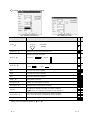
4. GT Designer2 and GOT display
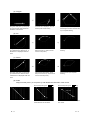
(a) Cautions for displaying straight line other than full line (dotted line, for example) in Bold
When straight line other than full line is drawn in bold, the line may not be displayed with its actual line
width on a personal computer. However, it will be displayed correctly on GOT. This phenomenon
does not mean data problem.
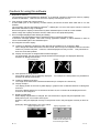
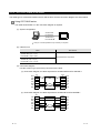
(b) Display of end points of straight line/line freeform/polygon
As shown below, the end points of straight line/line freeform/polygon are displayed differently
between GT Designer2 and GOT.
On GT Designer 2
(c) Start position for filling patterns
Some filling patterns may be differently displayed.
between GT Desginer2 and GOT.
On GOT
For example, the start position may be different
(d) Drawing of different type lines
The length of the dots varies in different dotted lines (for example: the chain lines).
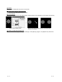
(e) Display of object
The display position of the memory data display in graph function is different between GT Designer2
and GOT.
Even if the display-start-line of a comment has been set, the comment will be displayed from the
first line on GT Designer2.
(f) Display magnification
When display magnification is changed, the connected lines or figures may be separated or the
filled-paint may be out of outline of the figure.
However, if they are displayed correctly on the preview screen, they will appear correctly on GOT as
well.
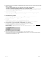
(Example): When filled-paint is out of the outline.
Display magnification: 200%
Display magnification: 100%
Position of Paint mark may be
shifted and the filled-paint may
be out of the figure outline.
A-2
A-2
5. Restrictions when the color setting is changed to the setting of less colors in the system environment (256
colors
2 colors)
• The color palette for setting color will be changed according to the updated settings.
• The color on the drawing screen will be kept the same as prior to the change.
If the color setting for a [red] rectangle-figure is changed to the 2 colors (B/W), the [red] color will remain.
• The colors of the image data (BMP format file) will be reduced when the project is stored, the screen is
closed and that image data is double-clicked.
6. Object function and device type
he object (bit lamp or word lamp),for which bit device setting and word device setting are separated,
cannot be converted between bit device and word device.
7. When device type is changed
Confirm the device type when the set bit device is changed from bit device into word device.
The device flag may be represented as “??” ,depending on the settings .
(Example) D0. b0
D0
D0.b5
??
8. OS setting
Set the font size as “Small Font” when setting OS (Windows) screen.
The GT designer2 dialog box cannot be displayed correctly if the font size is set as “Large font”.
9. When the toolbar icon appears in smaller size after startup of GT Desinger2
The toolbar icon may appear in smaller size right after GT Deseiger2 is started up.
To correctly display the icon, initialize it as instructed below.
(Click on [Project]
[References] from the menu, and select the toolbar tab. Click on
button in that tab.)
Reset All
10. When using GT Designer2 in the PC in which the OS other than Japanese version
The text may not be displayed correctly depending on the OS versions; some version include the fonts
incompatible with GT Designer2 or GOT.
A-3
A-3
REVISIONS
The manual number is given on the left bottom of the back cover.
Print Date
Manual Number
Apr., 2003
SH (NA)-080278E-A
Aug., 2003
SH (NA)-080278E-B
Revision
First edition
Partial corrections
Section 3.2, Section 3.5, Section 4.2, Section 5.4, Chapter 6
Partial additions
Section 5.1.1, Section 6.1.2, Section 6.2.1, Section 6.2.2
Additions
Section 9.5
Jan., 2004
SH (NA)-080278E-C
Partial corrections
Section 1.2, Section 3.1.1, Section 3.4, Section 3.2, Section 3.3.1,
Section 3.4.1, Section 4.3.1, Section 4.7.1, Section 4.8, Section 4.10.1,
Section 4.10.2, Section 5.4, Section 7.1.1, Section 7.3.6, Section 8.1.1,
Section 8.2.6, Section 9.1.1, Section 9.1.2, Appendix 2, Appendix 3.1
Partial additions
Section 2.1.2, Section 5.1.1, Section 8.1.4, Section 9.4
Additions
Section 7.3.7, Section 9.4.2, Section 9.6, Appendix 4
Japanese Manual Version SH-080279-E
This manual confers no industrial property rights or any other kind, nor does it confer any patent licenses. Mitsubishi
Electric Corporation cannot be held responsible for any problems involving industrial property rights which may occur as a
result of using the contents noted in this manual.
c
A-4
2003 MITSUBISHI ELECTRIC CORPORATION
A-4
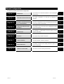
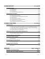
Manual Configuration
The following explains the manual configuration
The overview of this manual and features of the GT Designer2
Chapter 1
OVERVIEW
Chapter 2
SYSTEM CONFIGURATION
Chapter 3
SCREEN CONFIGURATION
OF GT DESIGNER2
The screen configuration for the GT Designer2 and the screen
Chapter 4
CREATING AND EDITING
SCREEN
The operations from the start-up of the GT Designer2 to saving
Chapter 5
DATA TRANSFER
OPERATION
The explanation on data transfer to the GOT and the transfer
Chapter 6
PRINTING PROJECT/FILE
OUTPUT
The project printing method is described.
6
Chapter 7
USING LIBRARY
The library utilization method is described.
7
Chapter 8
DRAW AND EDIT
The drawing of figures and the editing method for objects and
8
Chapter 9
USEFUL FUNCTIONS
A-5
are described.
The system configuration for using the GT Designer2 is
described.
customizing method are described.
screens are explained.
method are described.
figures are described.
1
2
3
4
5
9
The functions useful for drawing are described.
A-5
INTRODUCTION
Thank you for choosing Mitsubishi Graphic Operation Terminal (Mitsubishi GOT).
Read this manual and make sure you understand the functions and performance of the GOT thoroughly in
advance to ensure correct use.
CONTENTS
SAFETY PRECAUTIONS
A- 1
Cautions for using this software
A- 2
REVISIONS
A- 4
Manual Configuration
A- 5
INTRODUCTION
A- 6
CONTENTS
A- 6
Function Quick Reference
A-11
Manuals
A-18
Abbreviations and Generic Terms in This Manual
A- 19
How to Use This Manual
A- 23
1 OVERVIEW
1- 1 to 1- 5
1.1 Overview
1- 1
1.2 Feature
1- 2
2 SYSTEM CONFIGURATION
2.1 System Configuration in Creating Monitor Screen
2- 1 to 2- 6
2- 1
2.1.1 System configuration..................................................................................................... 2- 1
2.1.2 Operating environment.................................................................................................. 2- 1
2.2 System Configuration of Data Transfer and Document Creation
2- 3
2.2.1 System configuration..................................................................................................... 2- 3
2.2.2 RS-232C cable to be used ............................................................................................ 2- 5
3 SCREEN CONFIGURATION OF GT DESIGNER2
3.1 Screen Configuration and Basic Operation
3- 1 to 3-31
3- 1
3.1.1 Screen configuration and various tools ........................................................................ 3- 1
3.1.2 Basic operation of dialog box ........................................................................................ 3- 2
3.1.3 Operation of workspace ................................................................................................ 3- 4
3.2 Menu Configuration
A-6
3- 7
A-6
3.3 Toolbars
3- 10
3.3.1 Types of toolbars .......................................................................................................... 3-10
3.4 Customizing Screen Configuration and Toolbars
3-17
3.4.1 Customizing screen configuration................................................................................ 3-18
3.4.2 Customizing toolbars.................................................................................................... 3-20
3.4.3 Customizing GT Designer2 operating environment .................................................... 3-24
3.4.4 Display with frame ........................................................................................................ 3-28
3.4.5 Redisplaying drawing screen ....................................................................................... 3-29
3.5 How to Use Help
4 CREATING AND EDITING SCREEN
3-30
4- 1 to 4-28
4.1 Selecting Project at the Start of GT Designer2
4- 1
4.2 Creating a New Project
4- 2
4.3 Opening/Closing Project
4- 3
4.3.1 Opening project ............................................................................................................. 4- 3
4.3.2 Closing project ............................................................................................................... 4- 4
4.4 Providing Title on Project
4- 5
4.5 Creating a New Screen
4- 6
4.6 Opening/Closing Screen
4- 9
4.6.1 Opening screen ............................................................................................................. 4- 9
4.6.2 Closing screen .............................................................................................................. 4-12
4.7 Operating Multiple Screens
4-13
4.7.1 Cascading/tiling screens ............................................................................................. 4- 13
4.7.2 Making editing screen active........................................................................................ 4-14
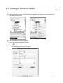
4.8 Changing Screen Property
4-15
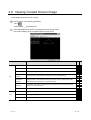
4.9 Viewing Created Screen Image
4-17
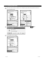
4.10 Copying/Deleting Screen
4-19
4.10.1 Copying screen data ................................................................................................. 4- 19
4.10.2 Deleting screen data ................................................................................................. 4- 21
4.11 Setting Screen Switching Device
4-23
4.12 Data Check
4-25
4.13 Saving Project
4-27
4.13.1 Overwriting and saving project.................................................................................. 4- 27
4.13.2 Saving as project name............................................................................................. 4- 27
4.14 Ending GT Designer2
A-7
4-28
A-7
5 DATA TRANSFER OPERATION
5.1 Type and Size of Transfer Data to GOT
5- 1 to 5-36
5- 1
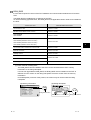
5.1.1 Data type to be installed on GOT ................................................................................. 5- 1
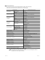
5.1.2 Memory space required for data transfer ..................................................................... 5- 8
5.2 Transferring data with RS-232C cable
5-12
5.2.1 Setting communication................................................................................................. 5-15
5.2.2 Getting built-in memory information............................................................................. 5-16
5.2.3 Uploading...................................................................................................................... 5-17
5.2.4 Installing ROM_BIOS ................................................................................................... 5-18
5.2.5 Installing OS ................................................................................................................. 5-21
5.2.6 Downloading monitor data ........................................................................................... 5-23
5.2.7 Downloading special data ............................................................................................ 5-25
5.3 Transferring Data Using PC Card
5-26
5.3.1 Installing ROM_BIOS ................................................................................................... 5-28
5.3.2 Transferring OS, monitor data and special data ......................................................... 5-31
5.4 Error Message for Data Transfer
6. PRINTING PROJECT/FILE OUTPUT
6.1 Printing method
5-34
6- 1 to 6-12
6- 1
6.1.1 Setting method............................................................................................................... 6- 1
6.1.2 Setting items .................................................................................................................. 6- 2
6.2 Printing example
6- 7
6.2.1 Printer output ................................................................................................................. 6- 7
6.2.2 File output ..................................................................................................................... 6-11
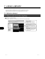
7. USING LIBRARY
7.1 What is Library?
7- 1 to 7-16
7- 1
7.1.1 What you need to know before using library ................................................................ 7- 1
7.1.2 Basic operation of library............................................................................................... 7- 3
7.2 Pasting Objects or Figures from Library
7- 5
7.3 Creating Original Library
7- 6
7.3.1 Registering objects or figures on library ....................................................................... 7- 6
7.3.2 Copying registered library/template .............................................................................. 7- 7
7.3.3 Deleting registered library/template .............................................................................. 7- 8
7.3.4 Editing registered objects and figures........................................................................... 7- 9
7.3.5 Changing library property............................................................................................. 7-10
7.3.6 Saving library to file ...................................................................................................... 7-11
7.3.7 Loading library from file ................................................................................................ 7-14
7.4 Utilizing Panelkit of GT Designer
A-8
7-16
A-8
8. DRAW AND EDIT
8- 1 to 8-26
8.1 Drawing Figures
8- 1
8.1.1 Drawing figures.............................................................................................................. 8- 1
8.1.2 Entering text................................................................................................................... 8- 6
8.1.3 Painting figures .............................................................................................................. 8- 8
8.1.4 Pasting figure data of BMP/DXF file ............................................................................ 8-10
8.2 Editing figure and object
8-14
8.2.1 Selecting figure and object........................................................................................... 8-14
8.2.2 Editing figures and objects ........................................................................................... 8-16
8.2.3 Grouping/Ungrouping multiple figures and objects ..................................................... 8-17
8.2.4 Undo and redo.............................................................................................................. 8-17
8.2.5 Aligning figures and objects ......................................................................................... 8-18
8.2.6 Changing attributes of figures and objects .................................................................. 8-21
8.2.7 Changing size of figures/objects .................................................................................. 8-23
8.2.8 Copying figures and objects consecutively ................................................................. 8-25
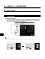
9. USEFUL FUNCTIONS
9.1 Edit Function
9- 1 to 9-31
9- 1
9.1.1 Batch setting of multiple objects/figures on the same screen(Property sheet) ........... 9- 1
9.1.2 Batch setting and managing objects/figures for each purpose(Category workspace) ..... 9- 3
9.1.3 Batch editing attributes of objects/figures scattered on multiple screens (Batch edit) ..... 9-10
9.1.4 Simple selection of overlapped figure (Data view) ...................................................... 9-14
9.1.5 Checking devices in use (Device list) .......................................................................... 9-15
9.2 Referring to Device Comment When Setting Devices
9-16
9.2.1 Importing device comment........................................................................................... 9-16
9.2.2 Check method of device comment .............................................................................. 9-18
9.3 Checking Monitor Data for Errors
9-20
9.4 Inputting multiple language
9-21
9.4.1 Input method................................................................................................................. 9-22
9.4.2 Precautions................................................................................................................... 9-25
9.5 Confirming the created data size
9-27
9.5.1 Confirmation method .................................................................................................... 9-27
9.5.2 Confirmation items........................................................................................................ 9-27
9.6 Utilizing other project data
9-28
9.6.1 Importing data............................................................................................................... 9-28
9.6.2 Cautions........................................................................................................................ 9-29
APPENDIX
App- 1 to App-13
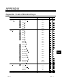
Appendix 1 List of Shortcut Keys
App- 1
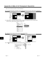
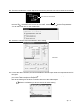
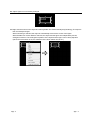
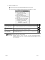
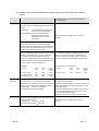
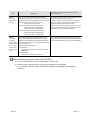
Appendix 2 Q&A of GT Designer2 Operation
App- 2
A-9
A-9
Appendix 3 Using Existing Data
App- 5
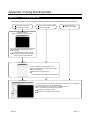
Appendix 3.1 Outline procedures.......................................................................................App- 5
Appendix 3.2 Precautions ..................................................................................................App- 6
Appendix 4 Applicable Monitor Data
App-10
Appendix 4.1 Opening monitor data .................................................................................App-11
Appendix 4.2 Uploading monitor data...............................................................................App-12
Appendix 4.3 Downloading monitor data ..........................................................................App-13
Appendix 4.4 Copying monitor data from one GOT unit to other unit with a PC card ....App-13
INDEX
A - 10
Index- 1 to Index- 2
A - 10
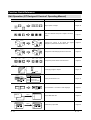
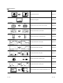
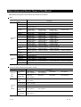
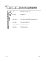
Function Quick Reference
Edit Operation (GT Designer2 Version1 Operating Manual)
Image
Function
Page
Align
Aligns objects or images
Page 8-18
Sets same attributes to objects or images in the same
screen
Page 9-1
Changes the color(s) of the objects and figures
arranged on plural screens at the same time
Page9-10
Changes the switch/lamp figures at the same time
Page9-10
Changes the preset devices at the same time
Page9-10
Overlapping images or objects
Page 9-14
Display the set device in list
Page 9-15
Input characters or comments in other language.
Page9-21
Imports BMP/DXF files
Page8-10
Utilizes other project data
Page9-28
Property sheet
Replace colors
Base 2
Base 2
Base 3
Base 1
Base 3
Base 1
Replace shapes
Base 2
Base 2
Base 3
Base 1
Base 3
Base 1
Replace devices
M11
M10
M12
M100
M101
M102
Data View
Select
Device list
Base 2
Base 3
D100
Numerical display
D200
ASCII display
D300
Panel meter display
Base 1
Multiple language input
Man.
Auto
English
Chinese
Import BMP/DXF file
BMP file
Import
DXF file
Import Project
Import
A - 11
A - 11
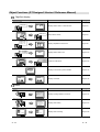
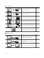
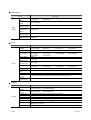
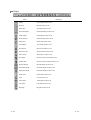
Object Functions (GT Designer2 Version1 Reference Manual)
Digit/font display
Image
Function
Page
Numerical display
334
D100
D100 : 334
Displays device value in numerical value
Page 5-61
Write value on device
Page 5-61
Display multipledevice value in list
Page 5-85
Displays device value in text
Page 5-100
Inputs text code device
Page 5-100
Displays hour/minutes, year/month/date
Page 5-112
Displays command
Page 5-118
Numerical input
45
D100
D100 : 45
Data list
D100 : 55
D101 : 122
D102 : 34
D100
55
D101
122
D102
34
ASCII display
D10 : 4241H(BA)
D11 : 4443H(DC)
ABCD
ASCII input
D10 : 4241H(BA)
D11 : 4443H(DC)
ABCD
Clock display
02/03/18
15:27
Comment display
RUN
STOP
Alarm
Image
Function
Page
Alarm list
02/04/18 13:25:40
RUN STOP
Displays message at alarm occurence
Page 5-137
Displays alarm history
Page 5-160
Displays alarm in floating
Page 5-186
Alarm history display
Time message
13:25 RUN A STOP
13:05 Hight limit over
13:03 Motor trip
Alarm flow
Alarm
A - 12
Alarm occur
A - 12
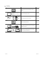
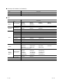
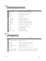
Animation
Image
Function
Page
Parts display
Part1
Display entered device
Page 5-191
Displays moving parts
Page 5-209
Displays device value via lamp color changing
Page 5-238
Displays device data on panel meter
Page 5-252
Displays device data in proportional level
Page 5-264
Displays device data in trend graph
Page 5-276
Displays device data in line graph
Page 5-289
Displays device data in bar graph
Page 5-301
Displays device data in statistics graph
Page 5-313
Displays device data in scatter grap
Page 5-323
Collect the device value and edit collected data on PC
Page 5-341
Part2
Parts movement display
Lamp display
Red
Blue
RUN
STOP
Panel meter display
Level display
Trend graph display
Line graph display
Bar graph display
Statistics graph display
Circle graph
Bar graph
Scatter graph display
Sampling
A - 13
A - 13
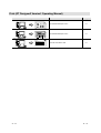
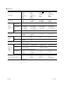
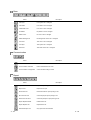
Touch switch
Image
Function
Page
Bit switch
MO : ON
OFF
Touch it to switch device ON/OFF
Page 5-348
Touch it to change bit device value
Page 5-363
Touch it to switch to the extended function screen
Page 5-368
Touchitto switch between the base and window screen
Page 5-376
Touch it to switch the monitored PLC station No.
Page 5-386
Used as the key for inputting numerical value/ASCII
Page 5-392
Data write switch
D100 :
200
350
Extended function switch
MOV
K
1
D1
MOV
K
2
D2
MOV
MOV
MOV
RST V
K
90 D162
K
110 D167
K
100 D172
Screen switching switch
Operation
Stop
Base 1
Base 2
Part No.switching switch
Change monitor
destination
Key code switch
A
A B C D
E F G H
Trigger
action
Image
Function
Page
Status observation function
Write
D100 : 0
150
Monitors status of device and write value to device or
operates GOT when condition meets
Page 5-411
Monitors status of device and write/read device data
when condition meets
Page 5-420
Outputs the device writing and sound at specified time.
Page 5-429
Recipe functioin
Write
/Read
D100 : 150
D101 : 300
D102 : 208
Time action function
A - 14
A - 14
Auxiliary
Image
Function
Page
Test
Script
Changes device value via test window in monitor
screen
Page 5-436
Controls GOT display by scripts
Page 5-439
Set overlay screen from other screens
Page 5-450
Restricts the password users
Page 5-52
Accumulates the offset device value in monitor device
address and monitor.
Page 5-48
Operates device values by expression and enables
objects using the operated value
Page 5-41
if(([b:X1]==OFF)&&([b:X2]==OFF)&&([b:X3]==OFF))
{[w:D10]=1;}
if(([b:X1]==ON)&&([b:X2]==OFF)&&([b:X3]==OFF))
{[w:D10]=2;}
if(([b:X1]==OFF)&&([b:X2]==ON)&&([b:X3]==OFF))
{[w:D10]=3;}
if(([b:X1]==OFF)&&([b:X2]==OFF)&&([b:X3]==ON))
{[w:D10]=4;}
Set overlay screen
Menu
Base 1
Menu
Base 3
Menu
Base 2
Security
*****
Offset
Numerical value input: D100
200
Write to D110
10
Offset device: D200
Data operation
D100 :
45
D100
180
A - 15
180
A - 15
External input/output
Image
Function
Page
Report
Collects numerical data when condition meets and
prints the numerical data and corresponding code.
Page 5-458
Outputs the GOT monitor screen to printer or PC card
Page 5-481
Uses operation panel to execute device writing
Page 5-487
Writes data read by barcode reader to device
Page 5-495
Outputs sounds
Page 5-500
Displays video
Page 5-504
Displays PC screens
Page 5-522
Hardcopy
Operation panel
X0
Bar code
1350
Sound
Video
RGB display
Data Transmission (GT Designer2 Version1 Operating Manual)
Image
Function
Page
Download
Transimits monitor screen data from PC to GOT
Page 5-1
Transmits monitor screen data from GOT to PC
Page 5-17
Upload
A - 16
A - 16
Print (GT Designer2 Version1 Operating Manual)
Image
Function
Page
Print screen
Print base/window/report screen
6-1
Print base/window/report screen
6-1
Prints list of the device used
6-1
Print screen list
Print device list
[Bit device]
[X list]
Network device
0-FF X0000 X0001 X0002 ......
X0013 X0016 X0017 ......
1-5 X0050 X0051 X0052 ......
[D list]
O-FF D0.b0
A - 17
A - 17
Manuals
The following manuals related to this product are available.
Order the manual as required referring to this table.
Reference manual
Manual number
Manual name
(model code)
GT Works2 Version1/GT Designer2 Version1 Operating Manual (Startup • Introductory Manual)
Describes methods of installing GT Designer2 and introductory drawing methods
SH-080250
(13JU25)
(Sold separately)
GT Designer2 Version1 Reference Manual
SH-080251
Describes the specifications and settings of each object function used in GT Designer2
(Sold separately)
(13JU26)
GOT-A900 Series Operating Manual
(GT Works2 Version1/GT Designer2 Version1 compatible Extended • Option Functions Manual)
Describes the following extended functions and optional functions applicable to GOT
Utility
Special module monitor
Module monitor
Font change
Ladder monitor
Network monitor
Servo amplifier monitor
SH-080253
System monitor
List editing
CNC monitor
(13JU28)
(Sold separately)
GOT-A900 Series User’s Manual
(GT Works2 Version1/GT Designer2 Version1 compatible Connection System Manual)
Describes the system configuration of which connection method is compatible with GOT-A900 series as well as
processing cables.
SH-080255
(13JR50)
(Sold separately)
GOT-A900 Series Operating Manual
(GT Works2 Version1/GT Designer2 Version1 compatible Gateway Functions Manual)
Describes the gateway function specifications, system configuration and methods of setting GOT-A900 series.
(Sold separately)
SH-080398E
(1D0J00)
A985GOT/A975GOT/A970GOT/A960GOT User's Manual
Provides performance specification, setting method, and communication board/communication module
installation method of each GOT.
SH-4005
(13JL70)
(Sold separately)
A950GOT/A951GOT/A953GOT/A956GOT User's Manual
Provides performance specification, setting method, and communication board/communication module
installation method of each GOT.
SH-080018
(13JL92)
(Sold separately)
GOT-F900 Series HARDWARE Manual [CONNECTION]
Explains the specifications, system configuration and connection diagram of each connection form available for
the GOT-F900 series.
JY992D94801
(09R805)
(Sold separately)
GOT-F900 Series OPERATION Manual [GT Designer2 Version]
Explains the drawing specifications, utility function/HPP mode/special function unit monitoring function
specifications, and dedicated monitor screen operation methods available for the GOT-F900 series.
JY997D09101
(09R813)
(Sold separately)
A - 18
A - 18
Abbreviations and Generic Terms in This Manual
Abbreviations and generic terms used in this manual are as follows:
GOT
Abbreviations and generic
terms
A985GOT-V
A985GOT
A975GOT
A970GOT
A97 GOT
A960GOT
A956WGOT
GOT-A900
series
A956GOT
A953GOT
A951GOT
A951GOT-Q
A950GOT
A95 handy
GOT
A95
GOT-F900
series
GOT
F940GOT
F930GOT-K
F930GOT
F920GOT-K
F940 handy GOT
F940WGOT
Description
A985GOT-TBA-V,
A985GOT-TBA,
A975GOT-TBA-B,
A975GOT-TBA-EU
A970GOT-TBA-B,
A970GOT-SBA,
A970GOT-TBA-EU,
A975GOT,
A960GOT-EBA,
A956WGOT-TBD
A956GOT-TBD,
A956GOT-TBD-M3,
A953GOT-TBD,
A953GOT-TBD-M3,
A951GOT-TBD,
A951GOT-TBD-M3,
A951GOT-QTBD,
A951GOT-QTBD-M3,
A950GOT-TBD,
A950GOT-TBD-M3,
A985GOT-TBD-V
A985GOT-TBD,
A975GOT-TBD-B,
A985GOT-TBA-EU
A975GOT-TBA,
A970GOT-TBD-B,
A970GOT-SBD,
A970GOT-SBA-EU,
A970GOT
A960GOT-EBD,
A970GOT-TBA,
A970GOT-LBA,
A970GOT-LBA-EU
A956GOT-SBD,
A956GOT-SBD-M3,
A953GOT-SBD,
A953GOT-SBD-M3,
A951GOT-SBD,
A951GOT-SBD-M3,
A951GOT-QSBD,
A951GOT-QSBD-M3,
A950GOT-SBD,
A950GOT-SBD-M3,
A956GOT-LBD,
A956GOT-LBD-M3
A953GOT-LBD,
A953GOT-LBD-M3
A951GOT-LBD,
A951GOT-LBD-M3
A951GOT-QLBD,
A951GOT-QLBD-M3
A950GOT-LBD,
A950GOT-LBD-M3
A975GOT-TBD,
A970GOT-TBD,
A970GOT-LBD,
A960GOT-EBA-EU
A950GOT-SBD-M3-H, A950GOT-LBD-M3-H, A953GOT-SBD-M3-H, A953GOT-LBD-M3-H
A956GOT,
A950GOT
F940GOT-SWD-E,
F930GOT-BBD-K-E
F930GOT-BWD-E,
F920GOT-BBD5-K-E,
F940GOT-SBD-H-E,
F943GOT-SBD-H-E,
F940WGOT-TWD-E
A953GOT,
A951GOT,
A951GOT-Q,
F940GOT-LWD-E,
F943GOT-SWD-E,
F943GOT-LWD-E
F933GOT-BWD-E
F920GOT-BBK-E
F940GOT-LBD-H-E,
F943GOT-LBD-H-E,
F940GOT-SBD-RH-E,
F943GOT-SBD-RH-E,
F940GOT-LBD-RH-E,
F943GOT-LBD-RH-E
Communication board/communication module
Abbreviations and generic terms
Communication
board
Communication
module
A - 19
Description
Bus connection
board
A9GT-QBUSS,
A9GT-50WQBUSS,
A9GT-QBUS2S,
A9GT-50WBUSS
A9GT-BUSS,
A9GT-BUS2S,
Serial
communication
board
A9GT-RS4,
A9GT-50WRS4
A9GT-RS2,
A9GT-RS2T,
A9GT-50WRS2,
Bus connection
module
A9GT-QBUS2SU,
A7GT-BUS2S
A9GT-BUSSU,
A9GT-BUS2SU,
A7GT-BUSS,
Data link module
A9GT-QJ71LP23,
A7GT-J71AT23B
A9GT-QJ71BR13,
A7GT-J71AP23,
A7GT-J71AR23,
Network module
A7GT-J71LP23,
A7GT-J71BR13
CC-Link
communication
module
A8GT-J61BT13,
A8GT-J61BT15
Ethernet
communication
module
A9GT-J71E71-T
A - 19
Option Module
Abbreviations and generic
terms
Option
Module
External I/O
module
Printer interface
module
Memory card
interface module
Video/RGB mixed
input interface
module
Video input
interface module
RGB input
interface module
Description
A9GT-70KBF,
A8GT-50KBF
A9GT-50PRF type
A1SD59J-MIF
A9GT-80V4R1
A9GT-80V4
A9GT-80R1
Option
Abbreviations and generic terms
Backlight
Debug stand
Memory board
Option
Ten-key panel
Bus connector
conversion box
Bus distance
connector box
Protective sheet
Attachment
PC card (memory
card)
Flash PC card
Compact Flash
PC card
Connector
conversion box
Description
A9GT-80LTT,
A9GT-70LTTBW,
A9GT-80STAND,
A9GT-FNB,
A9GT-FNB8M,
F9GT-40FMB,
A8GT-TK
A9GT-70LTTB,
A9GT-50LT,
A9GT-70STAND,
A9GT-FNB1M,
A9GT-QFNB,
F9GT-40UMB
A9GT-70LTT,
F9GT-40LTS,
A9GT-50WSTAND,
A9GT-FNB2M,
A9GT-QFNB4M,
A9GT-70LTS,
F9GT-30LTB
A9GT-50STAND
A9GT-FNB4M,
A9GT-QFNB8M,
A9GT-70PSC,
F9WGT-40PSC,
A85GT-95ATT,
A9GT-60PSC,
F9GT-40PSC,
A87GT-96ATT,
A9GT-50WPSC,
F9GT-30PSC
A87GT-97ATT
A7GT-CNB
A9GT-QCNB
A9GT-80PSC,
A9GT-50PSC,
A77GT-96ATT,
Abbreviations of PC card with JEIDA Ver4.2 (PCMCIA Ver2.1)
A9GTMEM-10MF,
A9GTMEM-20MF,
A9GTMEM-40MF
Abbreviation of Compact FlashTM (Compact FlashTM produced by Sun Disk.)
F9GT-HCNB
Software
Abbreviations and generic terms
GT Works2
Version1
GT Designer2
Version1
GT Designer2
GT Simulator2
Software
GT SoftGOT2
GT Converter
GX Developer
GX Simulator
DU/WIN
A - 20
Description
SW1D5C-GTWK2-E,
SW1D5C-GTWK2-EV
SW1D5C-GTD2-E,
SW1D5C-GTD2-EV
Abbreviation of GOT900 series graphic software-GT Designer2
Abbreviation of GOT900 series screen simulator-GT Simulator2
Abbreviation of monitoring software-GT SoftGOT2
Abbreviation of GOT900 series data conversion software-GT Converter
Abbreviation of SW D5C-GPPW(-V)/SW D5F-GPPW(-V) type software package
Abbreviation of SW D5C-LLT(-V) type download test tool function software package
(SW5D5C-LLT(-V) or later)
Abbreviation of FX-PCS-DU/WIN
A - 20
License (for GT SoftGOT, GT SoftGOT2)
Abbreviations
terms
and
generic
Description
License
A9GTSOFT-LKEY-P (for DOS/VPC)
License FD
SW5D5F-SGLKEY-J (for PC CPU module)
CPU
Abbreviations and generic
terms
QCPU
QnACPU
ACPU
Description
QCPU (Q Mode)
Q00JCPU,
Q02HCPU,
Q12PHCPU,
Q00CPU,
Q06HCPU,
Q25PHCPU
Q01CPU,
Q12HCPU,
QCPU (A Mode)
Q02CPU-A,
Q02HCPU-A,
Q06HCPU-A
QnACPU type
Q2ACPU,
Q3ACPU,
Q2ACPU-S1,
Q4ACPU,
Q2AHCPU,
Q4ARCPU
Q02CPU,
Q25HCPU,
Q2AHCPU-S1,
QnASCPU type
Q2ASCPU,
Q2ASCPU-S1,
Q2ASHCPU,
Q2ASHCPU-S1
AnUCPU
A2UCPU,
A2UCPU-S1,
A3UCPU,
A4UCPU
AnACPU
A2ACPU,
A2ACPU-S1,
A3ACPU
AnNCPU
A1NCPU,
A2NCPU,
A2NCPU-S1,
AnCPU type
AnUCPU,
AnACPU,
AnNCPU
AnUS(H)CPU
A2USCPU,
A2USCPU-S1,
A2USHCPU-S1
AnS(H)CPU
A1SCPU,
A1SHCPU,
A1SCPUC24-R2,
A2SHCPU,
A2SCPU,
A2SHCPU-S1
A1SJ(H)CPU
A1SJCPU,
A1SJCPU-S3,
A1SJHCPU
AnSCPU type
AnUS(H)CPU,
AnS(H)CPU,
A1SJ(H)CPU
A1FXCPU
A1FXCPU
A2CCPU,
A0J2HCPU,
A3NCPU
A2SCPU-S1,
A2CCPUC24,
A2CJCPU
FX0 series,
FXON series,
FX1N series,
FX1NC series,
FX2C series,
FX2N series,
FX(2N)-10GM/20GM series
FXOS series,
FX1S series,
FX2NC series,
FX1 series,
FX2 series,
Motion controller
CPU (A series)
A273UCPU,
A373CPU,
A171SCPU,
A171SHCPU,
A172SHCPUN,
A273UHCPU,
A373UCPU,
A171SCPU-S3,
A171SHCPUN,
A173UHCPU,
A273UHCPU-S3,
A373UCPU-S3,
A171SCPU-S3N,
A172SHCPU,
A173UHCPU-S1
Motion controller
CPU (Q series)
Q172CPU,
Q173CPU
FA controller
LM610,
LM7600,
MELDAS C6/C64
FCA C6,
FCA C64
FXCPU
Motion
controller
CPU
A - 21
LM8000
A - 21
Other PLC
Abbreviations and generic terms
C200H,
C200H
C200HE),
CV500,
CVM1-CPU11,
CJ1M,
CPM2C,
CQM1,
CV1000,
CVM1-CPU21,
CPM1,
CPM1H
C1000H,
CV2000,
CS1,
CPM1A,
C2000H,
CVM1-CPU01,
CS1D,
CPM2A,
GL60S,
GL130,
MP-930,
GL60H,
CP-9200SH,
MP-940,
GL70H,
CP-9300MS,
MP-9200(H),
GL120,
MP-920,
PROGIC-8
SLC500 series
SLC500-20,
SLC5/02,
SLC500-30,
SLC5/03,
SLC500-40,
SLC5/04,
SLC5/01,
SLC5/05
MicroLogix1000
series
1761-L10BWA,
1761-L16BWB,
1761-L32BWB,
1761-L20BWA-5A,
1761-L10BWB,
1761-L16BBB,
1761-L32BBB,
1761-L20BWB-5A
1761-L16AWA,
1761-L32AWA,
1761-L32AAA,
1761-L16BWA,
1761-L32BWA,
1761-L20AWA-5A,
MicroLogix1500
series
1764-LSP
JW-21CU,
JW-33CUH,
JM-100CU,
JW-22CU,
JW-50CUH,
Z-512J
JW-31CUH,
JW-70CUH,
JW-32CUH,
JW-100CUH,
PROSEC T
series
T3,
T3H,
T2E,
T2N
PROSEC V
series
Model3000,
S2T
Omron PLC
Yaskawa PLC
AllenBradley
PLC
Sharp PLC
Toshiba
PLC
SIMATIC S7-300series,
Large-sized H
series
H-302(CPU2-03H),
H-4010(CPU3-40H),
H-1002(CPU2-10H),
H-700(CPU-07Ha),
H-200 to 252
series
H-200(CPU-02H,CPE-02H),
H-252(CPU22-02H),
H-252C(CPU22-02HC, CPE22-02HC)
H-250(CPU21-02H),
H-252B(CPU22-02HB),
H series board
type
H-20DR,
H-20DT,
HL-40DR,
H-28DR,
H-28DT,
HL-64DR
H-40DR,
H-40DT,
H-64DR,
H-64DT,
EH-150 series
EH-CPU104,
EH-CPU208,
EH-CPU308,
EH-CPU316
FP0-C16CT,
FP2,
FP5,
FP-M(C32TC)
FP0-C32CT,
FP2SH,
FP10(S),
FP1-C24C,
FP2-CCU,
FP10SH,
FP1-C40C,
FP3,
FP-M(C20TC),
Matsushita Electric Works PLC
A - 22
series (C200HX, C200HG,
SIMATIC S7-200 series,
SIMATIC S7-400 series
SIEMENS PLC
HITACHI
PLC
(HIDEC H
series)
Description
C200HS,
H-702(CPU2-07H),
H-300(CPU-03Ha),
H-2002(CPU2-20H),
H-2000(CPU-20Ha)
A - 22
How to Use This Manual
Specification of symbols used in this manual
Indicates the operation steps.
Brackets used for the menu and items differ.
[ ] : Refers to menu in menu bar.
Refers to dialog box item or GOT utility
menu.
: Refers to dialog box buttons or PC
keyboard.
Shows functions applicable to GOT-A900 series
(GOT-A900) GOT-F900 series (GOT-F900).
" " , Applicable
" ",N/A
Point
Refers to information required for
operation.
Refers to information useful for
operation.
Remark Refers to supplementary
explanations.
Shows the items including detailed explanation
(manual and the chapter, section, item).
A - 23
A - 23
1. OVERVIEW
1
1.1 Overview
This manual explains the GT Designer2 system configuration, GT Designer2 screen configuration, basic
dialog box operation, creation of new project, data transfer to GOT and convenient operation for screen
editing.
Manuals
Three types of manuals are available for GT Designer2.
Refer to the appropriate manual depenfding on the purpose.
The manuals below are stored in PDF files and included with the product.
Purpose
Startup • Introductory
Manual
Reference Manual
Operating Manual
Details
Install the product into the personal computer
Details
Create a project
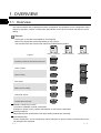
Overview
Create screens
Overview
Draw figures
Overview
Make common settings
Overview
Arrange/set objects
Overview
Transfer data to the GOT
Overview
Details
Details
Details
Details
Details
Startup & Introductory manual
The product installation method is described.
Examples of simple screen creation and operation on the GOT are described.
Reference Manual
Object/figure/screen specifications and object setting methods are described.
Operating Manual
Screen configuration, screen customizing, and procedures from project creation to data transfer on the
GT Designer2 are described.
1-1
1-1
1.2 Feature
The GT Designer2 has various functions to improve the drawing efficiency.
Main functions of the GT Designer2 are described below:
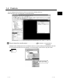
Easy to know the overall project ........................
1
Section 3.1.3 Operation of
workspace
Settings of the overall project such as created screens or common settings are displayed on the tree.
It is convenient to know the current settings, to check progress of work and to copy the screen.
A screen can be newly
created, copied or deleted.
1-2
1-2
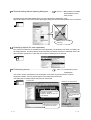
Easy to manage objects for each application ....
Item 9.1.2 Managing object/ figure
for each application
The overall project settings are displayed on the tree by category (type).
Classification for each application allows simple management of objects.
Managed for each application.
Easy to select parts frequently used ..................
Chapter 7 Using library
Objects or figures can be registered and pasted on the screen.
Objects or figures frequently used may be registered as buttons on the toolbar.
Pasting
Pasting from toolbar
Simple edit of parts
Part objects or figures once registered can be re-edited with the dedicated editor (library
editor).
Double click
Edit with dedicated editor
1-3
1-3
Shortest setting without opening dialog box ......
Item 9.1.1 Batch setting of multiple
objects/figures on the
same screen
All setting items and setting details being currently selected are displayed in a list.
Objects and figures can be set without opening the dialog box and the setting details can be checked.
Setting without opening
dialog box
Classifying objects for each application
Since the touch switches are classified for each application, the desired touch switch for setting can
be simply selected. The lamp display function and the part display function are classified into the bit
device and the word device. In this way, the number of setting items is reduced.
Customizing screen ...........................................
Item 3.4.1 Customizing screen
configuration
The screen can be customized for the workspace, movement of property sheet or toolbars
display/non-display. You may create figures in the preferred environment.
The dialog box for setting objects may also be customized.
GT Designer2
Dialog box for object setting
Movement and display/non-display
of toolbar is available.
Display/non-display for each icon
is also allowed.
Only checked items
are set.
Workspace or property
sheet can be moved.
1-4
1-4
Quick selection of desired screen for editing .....
Item 4.6.1 Opening screen
Double click the screen in the project workspace to display the desired screen for editing.
The screen can be displayed
by double clicking the screen
in the workspace.
Quick selection of desired part for editing..........
Item 9.1.5 Simple selection of
overlapped figure
Objects or figures set on the screen can be displayed in a list.
If multiple objects or figures are overlapped, it can be simply selected from the data list.
Currently selected objects or figures can also be checked.
Real time check of settings in graphic display (view direct)
Setting on the property sheet or the dialog box is quickly displayed on the screen.
Since the screen display can be checked, a screen as you wish can be smoothly created.
Quickly displayed
1-5
Quickly displayed
1-5
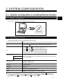
2. SYSTEM CONFIGURATION
2.1 System Configuration in Creating Monitor Screen
2
2.1.1 System configuration
The system configuration of GT Designer2 is shown below:
GT Works2 Version1 or
GT Designer2 Version1
PC
2.1.2 Operating environment
The operating environment of GT Designer2 is shown below:
Item
Details
PC
PC with Pentium
R
200 MHz or more that allows operation of the OS below.
Microsoft
Windows
98 operating system
Microsoft
Windows
Millennium Edition operating system
Microsoft
WindowsNT
Workstation4.0 operating system 2
Microsoft
Windows
2000 Professional operating system 2
Microsoft® Windows® XP Professional operating system 1 2
R
R
R
R
R
OS
R
R
R
Microsoft® Windows® XP Home Edition operating system
1
2
Computer main unit
Refer to "Used Operating System and performance required for personal computer main
unit" on the next page.
CPU
Required memory
Hard disk space
Installation: 250 MB or more
Operation : 50 MB or more
Disk drive
CD-ROM disk drive
Display color
256 colors
Display
Resolution of 800
Others
Installation of Internet Explorer Ver. 5.0 or later is required.
600 dots or more
1 "Compatibility mode", "user's easy switching" and "desktop theme (font) change" are not supported.
2 The authority of the administrator is required when installing GT Designer2 into WindowsNT Workstation4.0,
Windows 2000 Professional, Windows XP Professional or Windows XP Home Edition; when using GT
Designer2 on Windows XP Professional or Windows XP Home Edition.
R
R
R
R
2-1
R
R
2-1
Point
Regional Settings of Windows
R
control panel
Depending on the language of your Operating System, this software may not start.
In such a case, start this software after setting the Regional Settings within Control
Panel of Windows to "English".
R
Used Operating System and performance required for personal computer main unit
2
Operating System
Performance required for personal computer main unit
CPU
Required memory
Microsoft Windows 98 operating system
Pentium 200MHz or more
64MB or more
Microsoft® Windows® Me operating system
Pentium® 200MHz or more
64MB or more
Microsoft® WindowsNT® Workstation 4.0 operating system
Pentium® 200MHz or more
64MB or more
Microsoft® Windows® 2000 Professional operating system
Pentium® 200MHz or more
64MB or more
Pentium II® 300MHz or more
128MB or more
®
®
®
®
Microsoft Windows XP Professional operating system
Microsoft® Windows® XP Home Edition operating system
2-2
®
2-2
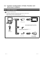
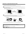
2.2 System Configuration of Data Transfer and
Document Creation
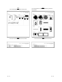
2.2.1 System configuration
Using GOT-A900 series
The system configuration using the GOT-A900 series is shown below.
Refer to Section 2.2.2 for the RS-232C cable.
Refer to the GOT user's manual (Details) for the PC card.
POWER
GOT-A900 series
RS-232C cable
PC
The OS program and monitor screen data
can be transferred (written) to the PC card.
PC card in compliance with JEIDA Ver. 4.2
(in compliance with PCMCIA 2.1)
GT Designer2
Printer cable
2-3
Printer compatible
with Windows R
2-3
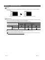
Using GOT-F900 series
The system configuration using the GOT-F900 series is shown below.
Refer to Section 2.2.2 for the RS-232C cable.
RS-232C cable
GOT-F900 series
PC
Printer cable
GT Designer2
2-4
Printer compatible
R
with W indows
2-4
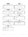
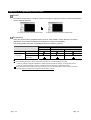
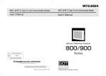
2.2.2 RS-232C cable to be used
The cable type for connection between the PC and the GOT and the connection diagram are shown below.
Using GOT-A900 series
The cable shown below or in the connection diagram is required.
(1) System configuration
AC30R2-9SS
FX-232CAB-1
AC30R2-9P 1
F2-232CAB-1 1
PC
GOT
1 9-25 pin converter (Diatrend Corp. D232J31) is required.
(2) Cable for use
Cable
Manufacturer
AC30R2-9SS (9 pin - 9 pin)
FX-232CAB-1 (9 pin - 9 pin)
Mitsubishi Electric Corporation
AC30R2-9P (9 pin - 25 pin)
F2-232CAB-1 (9 pin - 25 pin)
(3) Connection diagram
Use the screw-in type (inch screw) connector for the GOT.
(a) Connection diagram for cables equivalent to AC30R2-9SS and FX-232CAB-1
RXD
TXD
RTS
CTS
DSR
SG
DTR
PC
2
3
7
8
6
5
4
GOT
2
3
7
8
6
5
4
RXD
TXD
RTS
CTS
DSR
SG
DTR
Shield
(b) Connection diagram for cables equivalent to AC30R2-9P and F2-232CAB-1
TXD
RXD
RTS
CTS
DSR
SG
DTR
PC
2
3
4
5
6
7
20
GOT
2
3
7
8
6
5
4
RXD
TXD
RTS
CTS
DSR
SG
DTR
Shield
2-5
2-5
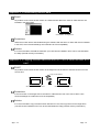
Using GOT-F900 series
The cable shown below or in the connection diagram is required.
(1) System configuration
FX-232CAB-1
F2-232CAB-1
GOT
PC
(2) Cable for use
Cable
Manufacturer
AC30R2-9SS (9 pin - 9 pin)
FX-232CAB-1 (9 pin - 9 pin)
Mitsubishi Electric Corporation
(3) Connection diagram
Use the screw-in type (inch screw) connector for the GOT.
(a) Connection diagram for cables equivalent to FX-232CAB-1.
RXD
TXD
RTS
CTS
DSR
SG
DTR
GOT
2
3
7
8
6
5
4
PC
2
3
7
8
6
5
4
RXD
TXD
RTS
CTS
DSR
SG
DTR
Shield
(b) Connection diagram for cables equivalent to F2-232CAB-1.
TXD
RXD
RTS
CTS
DSR
SG
DTR
GOT
2
3
7
8
6
5
4
PC
2
3
4
5
6
7
20
RXD
TXD
RTS
CTS
DSR
SG
DTR
Shield
Point
(1) Cable to be used
The cable for the Version A or later cannot be used.
The RS-232C cable for the Version A or later has the version name at the upper
right of the model on the connector. Check the version.
AC30R2-9SS
A
(2) Cable to be created
Use the F2-232CAB-1 connection cable when the PLC CPU and the GOT are
used at the same time with FX-2PIF by connecting the F940GOT or the
F930GOT to the A series CPU or the FX series CPU through the RS-422 cable.
2-6
2-6
3. SCREEN CONFIGURATION OF
GT DESIGNER2
3.1 Screen Configuration and Basic Operation
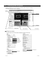
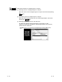
3.1.1 Screen configuration and various tools
3
The screen configuration and various tools are described.
Title bar
Menu bar
Toolbars
Title bar
Data view
All object functions
and figures on the
screen are displayed
in a list.
Section 9.1.5
Created screen
Status bar
Workspace
Settings on the overall
project such as created
screen and common
settings are displayed
in tree.
Section 3.1.3
Property sheet
Attributes of selected
screen, objects and figures
are displayed.
Settings can be made here.
Section 9.1.1
Library image list
Library is displayed.
Objects/figures in library can be
pasted.
Part image list
Parts used in the part display
function are displayed.
GT Designer2 Version1
Reference Manual
Chapter 7
Dropdown menu
3-1
3-1
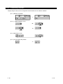
3.1.2 Basic operation of dialog box
1) Tab
(3) List box
(5) Text box
(6) Spin box
3
(7) Radio button
(8) Function list
check box
(4) Check box
(1) Tab
To switch the tab, click
.
When the function list check box is
checked, the extension tab is
additionally displayed.
The extension tab allows more
detailed settings than the basic tab.
(2) Command button
Command buttons such as [OK] and
[Cancel] are provided. Click each
button to perform the item.
(3) List box
Click
to display the selection list.
Click the item for selection.
(4) Check box
To execute an item, click
mark.
(2) Command button
(10) Creation of new folder
(12) Detail
(11) List
(9) To upper level folder
Extension tab
to put the
(5) Text box
Input text from the keyboard.
(6) Spin box
Input the value directly or click
to change the value.
(7) Radio button
Click
for the item to be selected.
(8) Function list check box
To display the extension tab, click
to put the
mark.
(9) Up One Level
One upper level than the current
folder is displayed.
(10)Create New Folder
A new folder is created.
(11) List
The folders and files which are open
currently are displayed in a list.
(12)Details
Details of the folders and files which
are open currently are displayed.
(8) Function list check box
When this is checked, the extension tab is additionally displayed.
3-2
3-2
(13)View of table
To select each item, click the left end
of the table.
(13) View of table
3-3
3-3
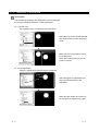
3.1.3 Operation of workspace
Workspace
The overall project settings are displayed in a tree by data type.
It is easy to manage and edit the overall project data.
Ex. 1) Screen copy
The existing screen is copied using the workspace.
Select the copy source screen and right
click on the mouse to select the [Copy]
menu.
Right click the mouse again to select
the [Paste] menu.
When the screen property is set, the
screen is copied.
Ex. 2) Part registration
A figure is registered as a part using the workspace.
Drag
Select the figure for registration and
drag it to the Parts folder in the
workspace.
When the part number and name are
set, the figure is registered as a part.
3-4
3-4
Workspace type
Types of the workspace are described here.
Project workspace
Overall project settings such as created screens and common settings are displayed in a tree.
It is convenient to see the project details, to check the work progress and to copy a screen.
Set overlay screen
Set overlay screen
status is displayed
in a tree.
When this is checked,
the set overlay screen
status is displayed in
a tree.
Screen
The created screen is displayed in a tree by type
(base screen, window screen and report screen).
Common settings
The object function settings used in common for the project
are displayed in a tree.
When an item is double clicked, the setting dialog box for
each function is displayed.
Common file
Files of multiple object functions (part, comment and voice)
which are used in common are displayed in a tree.
Available functions
• Right click the mouse to select basic commands
such as New Screen, Open or Copy.
Ex.) Right click the window screen.
• Dragging a figure to the project workspace allows
registration of a part.
Ex.) Drag a figure.
Drag
3-5
3-5
Category workspace
The overall project setting is displayed in a tree by category (type).
Classification for each application simplifies management and editing of objects.
Section 9.1.2 Managing and batch changing objects/figures for each application
Library workspace
Objects or figures can be registered and pasted to the screen.
Chapter 7 Using Library
3-6
3-6
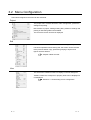
3.2 Menu Configuration
Commands assigned to the menu bar are described.
Project
The project menu contains functions of file management, preference
settings and printing.
New creation of project, reading existing files, preference settings and
printing of data being edited are available.
The recent file record can also be displayed.
Edit
The edit menu contains edit functions for created figures/objects.
If incorrect operation is done during edit, the screen can be returned
to the previous status. Copy, paste and grouping of objects and
figures are also allowed.
Chapter 8 Draw and edit
View
The view menu contains functions of display on the GT Designer2.
Toolbars, status bar, workspace or property sheet can be displayed or
not displayed.
Section 3.4.1 Customizing screen configuration
3-7
3-7
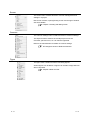
Screen
The screen menu contains functions of screen management and
settings in a project.
New screen creation, opening/closing screen and change of window
size are available.
Chapter 4 Creating and editing screen
Common
The common settings menu contains functions of common settings.
The object functions used for the overall project can be set.
Comment, part and voice, etc. can also be registered.
Refer to the manual below for details of common settings.
GT Designer2 Version1 Reference Manual
Figure
The figure menu contains functions of drawing figures.
Various figures can be drawn or figures can be filled. Image data can
also be imported.
Chapter 8 Draw and edit
3-8
3-8
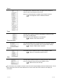
Object
The object menu contains functions of objects such as lamps or
switches witch are arranged on the screen.
Refer to the manual below for details of each object functions.
GT Designer2 Version1 Reference Manual
Tools
The tool menu contains functions of list display of set devices and
error check of setting items.
The data view can be displayed or not displayed.
Chapter 9 Convenient function
Communication
The communication menu contains functions of download, upload,
display of GOT memory information and communication settings.
Chapter 5 Data transfer operation
Window
The window menu contains functions of tiling multiple screens.
Clause 4.7 Operating multiple screens
Help
The help menu contains functions of viewing the PDF manual related
to the GT Designer2 and checking the software version.
Clause 3.6 How to use help
The commands in this chapter is shown for the case of the largest display of the GOT-A900 series. For the
GOT-F900 series, there are some differences for each model, and some models do not display all
commands.
3-9
3-9
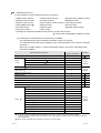
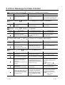
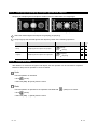
3.3 Toolbars
3.3.1 Types of toolbars
The following types of toolbars are available.
When desired toolbars are checked for display/non-display, the toolbars can be displayed/non-displayed
accordingly.
Standard items are displayed as icons.
Display items are displayed as icons.
Figure items are displayed as icons.
Object setting items are displayed as icons.
Figure edit items are displayed as icons.
Align items are displayed as icons.
Draw setting items are displayed as icons.
Communication setting items are displayed as icons.
Report function setting items are displayed as icons.
Favorite toolbars are displayed.
If you drag a displayed toolbar, it may be arranged as a window on the screen.
The following pages also describe details of each toolbar.
3 - 10
3 - 10
Main
Name
3 - 11
Description
New
New project file is created.
Open
Existing project file is opened.
Save project
Editing project is overwritten and saved on the existing file.
New Screen
New screen is created.
Open Screen
Specified screen is opened.
Cut
Figures and objects are cut.
Copy
Figures and objects are copied.
Paste
Figures and objects are pasted.
Undo
The last operation is cancelled to recover the status before change.
Redo
The last operation is repeated.
Screen Preview
Settings are displayed with the display image on the GOT.
Previous Screen
Screen with the number before the current screen number is opened.
Next Screen
Screen with the number next to the current screen number is opened.
Unopened Screens
Unopened screen is opened with "Previous/Next Screen" in the
ascending/descending order.
Screen Device List
List of devices used is displayed.
Data View
All figures and objects arranged on the screen are displayed in a list.
Comment
Comment to be displayed with the object function is registered.
Figure and Object
Objection of selection is switched to "Figure and Object."
3 - 11
View
Name
3 - 12
Description
Snap
Snap movement of the cursor is set.
Zoom
Screen display magnification rate/shrinkage rate is set.
Grid Interval
Grid interval is set.
Grid Color
Grid color is set.
ON, OFF
Screen is switched to the display of device ON/device OFF.
Device, Object ID
Device (Dev.) and object ID (ID) are displayed for each object.
Screen Color
Screen background color is set.
Screen Pattern
Screen background pattern is set.
Screen Background Color
Screen background color is set.
Workspace
Workspace is displayed.
Property sheet
Property sheet is displayed.
3 - 12
Figure
Name
3 - 13
Description
Line
Line is drawn.
Line FreeForm
Continuous line is drawn.
Rectangle
Rectangle is drawn.
Rectangle (Filled)
Filled rectangle is drawn.
Polygon
Polygon is drawn.
Circle
Circle is drawn.
Circle (Filled)
Filled circle is drawn.
Arc
Arc is drawn.
Sector
Sector is drawn.
Scale
Scale is drawn.
Text
Text is input.
Paint
Polygon and closed area are painted with the selected pattern.
Import Image
BMP format file is imported on the editing screen.
Import DXF
DXF format file is imported on the editing screen
3 - 13
Object
Name
3 - 14
Description
Switch
Touch switch function is set.
Bit Lamp
Bit lamp function is set.
Word Lamp
Word lamp function is set.
Numerical Display
Numerical display function is set.
ASCII Display
ASCII display function is set.
Numerical Input
Numerical input function is set.
ASCII Input
ASCII input function is set.
Time Display
Time display function is set.
Bit Comment
Bit comment function is set.
Word Comment
Word comment function is set.
Alarm History
Alarm history function is set.
User Alarm
Alarm list function (User Alarm) is set.
System Alarm
Alarm list function (System Alarm) is set.
Bit Parts Display
Bit parts display function is set.
Word Parts Display
Word parts display function is set.
Fixed Parts Display
Fixed parts display function is set.
Panel meter
Panel meter function is set.
Level
Level function is set.
Trend Graph
Trend graph function is set.
Line Graph
Line graph function is set.
Bar graph
Bar graph function is set.
3 - 14
Edit
Name
Description
Bring to Front
Selected figures and objects are arranged to front.
Bring to Back
Selected figures and objects are arranged to back.
Group
Selected figures and objects are grouped.
Ungroup
Grouping is canceled.
Flip Horizontal
Selected figure is flipped horizontally.
Flip Vertical
Selected figure is flipped vertically.
Rotate Left
Selected figure is rotated 90 degrees to the left.
Rotate Right
Selected figure is rotated 90 degrees to the right.
Edit Vortex
Length of freeform line or polygon line is changed.
Align
Selected figures and objects are aligned.
Figure
Only figures are selected.
Object
Only objects are selected.
Figure and Object
Figures and objects are selected.
Align
Name
3 - 15
Description
Align Left
Aligned with the selected leftmost figure or object.
Align Center (Horizontally)
Aligned at the center horizontally.
Align Right
Aligned with the selected rightmost figure or object.
Align Top
Aligned with the selected uppermost figure or object.
Align Center (Vertically)
Aligned at the center vertically.
Align Bottom
Aligned with the selected lowermost figure or object.
Align Across (Horizontally)
Selected figures and objects are evenly aligned in the horizontal direction.
Align Vertical (Vertically)
Selected figures and objects are evenly aligned in the vertical direction.
3 - 15
Draw
Name
Description
Line Style
Line style is set or changed.
Line Width
Line width is set or changed.
Line/Border Color
Line color is set or changed.
Fill Pattern
Fill pattern is set or changed.
Pattern Color
Fill color is set or changed.
Pattern Background
Fill background color is set or changed.
Text Color
Text color is set or changed.
Text Style
Text style is set or changed.
Solid Text
Text solid color is set or changed.
Communication
Name
Description
Communication with GOT
Data is transferred to GOT.
Communication with Card
Data is transferred to PC Card.
Communication Configuration
Communication setting is made
Report
Name
3 - 16
Description
Report Line
Report line (Rectangle) is drawn.
Report Text
Report text is input.
Numerical Print
Numerical value for report printing is set.
Bit Comment Print
Comment (Bit) for report printing is set.
Word Comment Print
Comment (Word) for report printing is set.
Report Repeat Header
Header line is set.
Report Repeat Line
Repeat line is set.
Selection Report Line
Only report lines are selected.
3 - 16
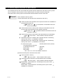
3.4 Customizing Screen Configuration and Toolbars
Screen configuration and toolbars can be customized on the GT Designer2 to facilitate operation by
users.
Screen configuration and toolbars customizing methods are described in this section.
Unused toolbars are not displayed.
Toolbars are displayed
as a window.
Size change
Workspace or property sheet is
moved to desired position.
3 - 17
Only toolbar icons necessary
for operation are displayed.
(Unnecessary icons are
not displayed.)
3 - 17
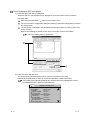
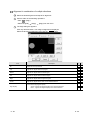
3.4.1 Customizing screen configuration
Display/non-display of tools, size change and display position change are available.
The areas shown below can be customized.
Toolbars
Data view
Status bar
Workspace
Property sheet
Library image list
Part image list
Display/non-display
Click the options in the menu below to display/non-display various tools.
Toolbars
Status bar
Workspace
Property sheet
Library list
Part image list
Data view
3 - 18
3 - 18
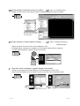
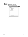
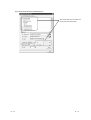
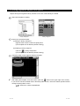
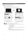
Size change
Click the buttons below to change the screen size:
: The selected screen is minimized.
: The selected screen is returned to the original size.
: The selected screen is maximized.
: The selected screen is closed.
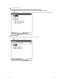
to pop up the workspace, property sheet and data view.
Click
(Ex.) Moving or changing size of workspace
Click
.
The workspace pops up as a window.
Change the window size of the workspace.
When it is dragged to the original position, full
(Toolbars size cannot be changed.)
display can be recovered.
A display frame appears
by dragging.
Remark
Customized screen
The GT Designer2 memorizes the customized settings of the screen configuration.
At the next start-up, the previously customized status screen is displayed.
3 - 19
3 - 19
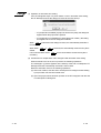
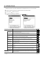
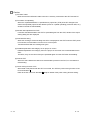
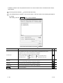
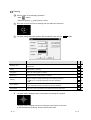
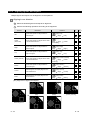
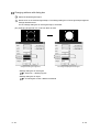
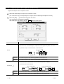
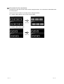
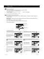
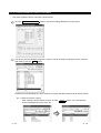
3.4.2 Customizing toolbars
Display image of icons can be changed and icons/toolbars can be added or deleted.
(Ex. 1) Deletion of toolbars
(Ex. 2)
Addition/deletion of icon
Addition
Deletion
(Ex. 3) Movement of icon
(Ex. 4) Icon grouping with partition
3 - 20
3 - 20
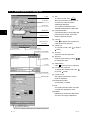
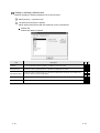
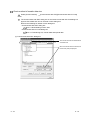
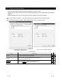
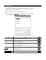
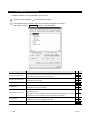
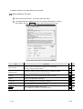
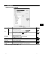
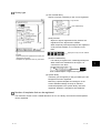
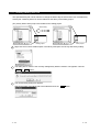
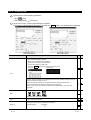
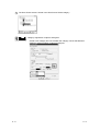
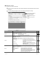
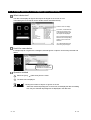
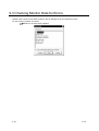
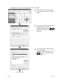
Adding or deleting toolbars/icons
Methods of adding or deleting toolbars/icons are shown below:
Select [Project]
[Preferences].
The preferences dialog box appears.
Add or delete toolbars/icons with the toolbar tab or the command tab.
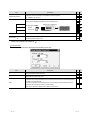
Toolbars tab
Toolbars are added or deleted.
Item
Description
Toolbars
Check the desired toolbars for addition. To delete it, remove the check.
Show Tool Tips
When the cursor is placed on the icon, check this to display the icon name.
With Shortcut Keys
When the cursor is placed on the icon, check this to display the shortcut key. (It is effective only
when the "Show Tool Tips" is displayed.)
Reset
Only the selected toolbars are set to default status.
Reset All
All toolbars are set to default status.
3 - 21
A
3 - 21
F
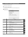
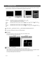
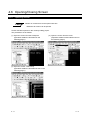
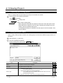
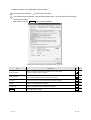
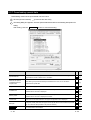
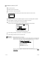
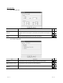
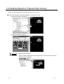
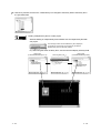
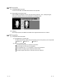
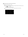
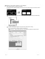
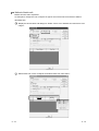
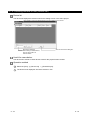
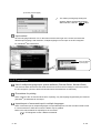
Command tab
Icons are added, deleted or moved with the procedures below:
(Ex. 1) Adding icon
Click the desired function for
addition and drag it to the
desired toolbar.
(Ex. 2) Deleting icon
Click the desired icon for
deletion and drag it outside
the toolbar.
3 - 22
3 - 22
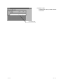
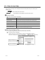
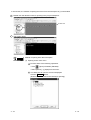
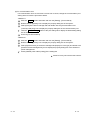
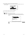
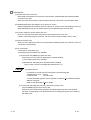
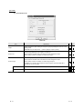
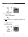
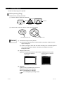
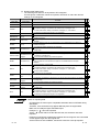
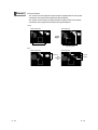
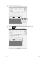
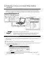
(Ex. 3) Moving icon
Select the desired icon for
movement and drag it to the
desired position.
When the toolbars are changed, click the
Close
button.
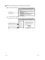
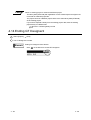
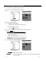
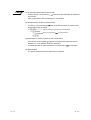
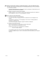
Deleting icon and inserting partition
While the preferences dialog box is open, select the icon and right click the mouse
to delete icon or to insert partition.
Delete
: Delete the selected icon.
Start Group : Insert a partition at the left of the icon.
It is convenient to group with icons.
When all icons at the right of the partition are deleted, the
partition is deleted as well.
3 - 23
3 - 23
3.4.3 Customizing GT Designer2 operating environment
Environment for the drawing screen is set.
Select [Project] - [Preferences] menu.
The preferences dialog box appears.
The drawing screen environment is set with operation tab/display tab items.
Operation tab
Operation setting for drawing screen is made.
Item
Figure/object
deselect-after create
Description
A
Checked
: After arranging objects, the selected status (status with handle) is reset.
Not checked : With the selected status (status with handle), figures/objects are arranged on the
drawing screen.
Checked
Tool de-select after
use
: After setting figures/objects, the tool selected status is reset. It is convenient to
arrange different figures/objects.
Not checked : After setting figures/objects, the selected status remains active. It is convenient to
arrange the same figures/objects continuously.
Checked
System setting on
new
: The system settings dialog box (GOT type, PC type, etc.) appears in creation of a
new project.
Not checked : The system settings dialog box (GOT type, PC type, etc.) does not appear in
creation of a new project.
Checked
Change object after
create
: After arranging objects on the drawing screen, the settings dialog box automatically
appears.
Not checked : After arranging objects on the drawing screen, the settings dialog box does not
automatically appear.
Checked
Auto File Save
Show "Select
Project" dialog when
you start GT
Designer2
3 - 24
: File is automatically saved.
Saving interval (5 to 720) is set.
Not checked : File is not automatically saved.
Checked
: When the GT Designer2 is started, the project selection dialog box (New, Open,
etc.) appears.
Not checked : When the GT Designer2 is started, the project selection dialog box (New, Open,
etc.) does not appear.
3 - 24
F
Point
(1) Operation in automatic save setting
If the GT Designer2 stops or a power failure occurs in automatic save setting,
the GT Desinger2 shows the dialog box below at the next start-up.
• If a project file is available (a project is saved in the past), this dialog box
appears when the project file is opened.
• If a project file is not available (no saving after new creation), this dialog
box appears when the GT Designer2 is started.
When Yes
recovered.
is selected on the dialog box above, the automatically saved file is
When either Yes or No is selected, the automatically saved recovery file is
erased.
It is recommended to select Yes and to check that the saved recovery file is
necessary.
(2) Precautions for multiple start of GT Designer2 with automatic save setting
When automatic save is set, do not perform the following operations.
The message in (1) above appears at the start-up of the 2nd or subsequent GT
Desinger2 and the automatically saved file is then erased.
Reset the automatic save for the following operations:
(a) After new creation, start the 2nd or subsequent GT Designer2 while editing
a project which has not been saved at all.
(b) Open the project which has been opened on the GT Designer2 with the 2nd
or subsequent GT Designer2.
3 - 25
3 - 25
View tab
Display for the drawing screen is set.
Snap
Item
Description
1
Dot value (1, 2, 4, 8 or 16) is selected for automatic arrangement of figures or objects on the screen.
Position
Grid
Position of grid display is selected.
Front : Grid is displayed at the front of the screen.
Back : Grid is displayed at the back of the screen.
None: Grid is not displayed.
Spacing
Grid spacing (2 to 64 dots) is set.
Color
Grid display color is selected.
Display items
A
(Ex.)
Front
Back
Items displayed on the GT Designer2 are checked.
(Ex.) Filling in white
Paint
When a closed figure is filled with "Paint," this item is selected to
display the filled status.
(Ex.) x 1000
Device
Object ID
This item is selected to display the device name set in the object.
This item is selected to display the object ID of each object.
The object ID is automatically put on each object.
It is convenient to display the object ID in setting the system
information.
Refer to the manual below for details of system information.
(Ex.) 10000
GT Designer2 Version 1 Reference Manual
(Ex.) Display of level
Object
This item is selected to display the set object.
Refer to the next page for details of
3 - 26
1.
3 - 26
F
1 Snap
Figures and objects are arranged with the dot value set in "Snap."
(Ex.)
Drawing a rectangle ([Snap] is set to 16 dots.)
Determine the start point by clicking.
Actual start position
Cursor position
(X=10, Y=12)
It is arranged at the closest position to the
coordinates of multiples of 16. (X=16,
Y=16)
(a) When the end point is determined, the cursor can only moved to the coordinates of
multiples of 16.
(b) When an object display position is determined or a figure is moved, the cursor moves
based on the dot value set in [Snap] as shown above.
key,
key,
key and
key on the keyboard
(c) One stroke of the
moves the cursor in the units of the set dot value.
key,
key,
key and
key
Set the [Snap] to one dot each and hit
each time on the keyboard to move the cursor 1 dot each. This facilitates drawing a fine
figure or position setting.
Display change from toolbars and menu
Items set on the display tab can be changed from toolbars and menu.
(1) Changing drawing screen display from toolbars (display setting)
Change of
ON/OFF status
Display/non-display of
device number
Object ID display/non-display
Snap value
Grid spacing
Grid color
Screen background color
Display magnification
(2) Changing drawing screen display from menu
Display magnification
Display/non-display of device,
object ID, paint and object
Grid display position
3 - 27
3 - 27
3.4.4 Display with frame
It is the function to display the outer frame on the drawing screen as if the GOT body frame is imaged.
With this function, a screen can be created with the image of the GOT body.
Standard
Handy
ET
Standard ...... Selectable on all GOT (except F920GOT (128
64)).
(This is not displayed on the GT SoftGOT.)
Handy........... Selectable when the GOT type is set to A95 GOT (320
240).
ET ................ Selectable when the GOT type is set to A94 GOT (320
Keypad......... Selectable when the GOT type is set to A920 GOT (128
80).
Select [View]
[Display with Frame]
Keypad
240) or F94 GOT (320
240).
64) or A930 GOT (240
[Standard]/[Handy]/[ET]/[Keypad] menu.
The frame is displayed according to the selected option.
Standard
This function allows an image of the GOT body on the drawing screen.
It is easy to edit a figure at an screen end.
No frame
With frame
Handy, ET and Keypad
This function allows an image of the GOT body on the drawing screen.
When a switch or an LED on the body image is clicked, device assignment for the operation switch
LED or the function switch and switch function for the function switch can be set.
It is easy to edit a figure at an screen end.
3 - 28
3 - 28
3.4.5 Redisplaying drawing screen
If paint is used, unpainted areas may occur.
Redisplay provides correct display.
Ex.) Moving an object on paint
Paint
Move an object on pain.
The figure shows unpainted areas.
Refresh the display with
[View]
[Redisplay] menu.
Select the [View] -> [Redisplay] menu.
Display the drawing screen correctly.
3 - 29
3 - 29
3.5 How to Use Help
Help is used for referring to the GT Designer2-relevant manual (PDF format) and confirming the
software version.
Point
Before viewing PDF format manual
Acrobat Reader must be installed to view PDF format manual
Operation method
Click on each menu item under [Help].
Item
Description
[Operating Manual]
This item is used for referring to GT Desginer2 Version1 operating manual.
[Reference Manual]
This item is used for referring to GT Designer2 Version1 reference manual.
[Index]
This item is used for viewing a PDF manual.
[About GTD2…]
This item is used for confirming the GT Designer2 version.
[Connect to MELFANSweb…]
This item is used for connecting to the MITSUBISHI ELECTRIC FA NETWORK
SERVICE ON WORLD WIDE, MELFANSweb homepage
PDF manual viewing procedure
(When [Operating Manual]/ [Reference Manual] is selected.)
The selected manual is displayed.
(Refer to the HELP of Acrobat Reader for details of Acrobat Reader operation.)
Manual list is displayed by clicking on INDEX MENU. (
in this section)
Switches the display to the
first page of the selected item
Returns to INDEX MENU.
3 - 30
3 - 30
PDF manual viewing procedure (When [Index] is selected.)
After operating
, following screen is displayed. Click on the desired manual.
Click
The selected manual is displayed.
(Refer to the HELP of Acrobat Reader for details of Acrobat Reader operation.)
Switches the display to the
first page of the selected item
Returns to INDEX MENU.
3 - 31
3 - 31
4. CREATING AND EDITING SCREEN
4.1 Selecting Project at the Start of GT Designer2
At the start of GT Designer2, the project selection dialog box is displayed.
Select whether a project is newly created or existing project data is edited.
From the PC start menu, select [Start]
[Program]
[MELSOFT Application]
[GT Designer2]
to start the GT Designer2.
The project selection dialog box is displayed.
4
Item
Select
project
Description
New
Click this to create a new project.
Open
Click this to edit an existing project data.
Show this dialog
next time you start
GT Designer2
When you do not want to display this dialog box at the next start of the GT Designer2,
uncheck this.
A
The operation proceeds to the following depending on the items selected.
New : Set [System environment] of a new project.
Section 4.3 Creating a new project
Open : Specifying a project save source for editing
Section 4.4 Opening a project
4-1
4-1
F
4.2 Creating a New Project
A new project is created.
Perform either of the following operations.
• Click
(New).
• Select [Project]
[New] menu.
The system environment dialog box appears. Perform the system settings.
For items other than [System settings], refer to the manual below:
GT Designer2 Version1 Reference Manual
4
Item
System
settings
Description
GOT type
The GOT type to be used is set.
PLC type
The PLC type to be connected is set.
Refer to the manual below for details of the PC type.
A
GT Designer2 Version1 Reference Manual
Color settings
Point
Screen color displayed on the GOT is set.
Select the color according to the GOT display color.
Change of GOT type
Refer to the manual below for cautions when changing GOT type.
GT Designer2 Version1 Reference Manual
After system settings, click the
OK
button to go to operation of New Screen.
Section 4.5 Creating a new screen
4-2
4-2
F
4.3 Opening/Closing Project
4.3.1 Opening project
A saved project data is read from the project save source.
Perform either of the following operations.
• Click
(Open).
• Select [Project]
[Open] menu.
The open dialog box is displayed.
Item
Description
Look in
Select the location where the project is saved.
File name
Set the project name for opening.
Files of type
Select the type of project for opening.
GTD file ( .GTD)
: Project data of GT Designer2 is opened.
DU-Win file ( .DUP) : Project data of DU-Win is opened.
GOT file ( .GOT) : Project data of GT Designer is opened.
Remark
A
(1) Using existing GOT data
• GOT800 series
: The data are converted to the monitor screen data for
the GOT-A900 series with the GT converter.
• A77GOT and 64GOT : The data are converted to the monitor data for the
GOT-A800 series and then converted to the monitor
screen data for the GOT-A900 series with the GT
converter.
Refer to the following for conversion to the monitor screen data for the
GOT-A900 series.
GT Converter Help function
4-3
4-3
F
(2) Using existing DU (data access unit) data
• DU series: Select the DU-WIN file and open the project data.
The DU-WIN file is the project data prepared with the FX-PCS-DU/WIN
drawing software.
Up to Ver. 1.01B, a temporary file is created in the some folder of DU-WIN file in
reading.
Accordingly, a write-enabled memory device (such as folppy disk and hard disk)
should be set to the write-enabled status.
The read screen data is compatible because the menu name and data handling
of the software DU-WIN are same.
• The base screen No. starts from No.0.
• The system information consists of control devices.
For the details, refer to the GOT-F900 SERIES OPERATION MANUAL (GT
Designer2 Version1).
Click the
Open
Remark
button to open the specified project.
Opening project directly
Double click the project data ( .GTD). The GT Designer2 starts with the project
data open.
4.3.2 Closing project
Close the open project.
Select [Project]
[Close] menu.
The open project data is closed.
4-4
4-4
4.4 Providing Title on Project
Detailed information (project ID, detailed explanation, author, etc.) for the project is set.
Select [Common settings]
[System environment] from the menu.
Double click [Project title] of the system environment.
The project title dialog box appears.
Set the following items and click the
OK
button.
Item
A
F
Project title is set as required.
Set the text within 32 characters.
Project title
Project ID
Description
1
Set the ID in the range of 1 to 4294967295.
Detailed Explanation
Project is explained as required.
Set the text within 512 characters.
(If a line feed is used, it is considered as 2 characters.)
Author
Author name is set as required.
Set the text within 8 characters.
Refer to the following for details of
1.
1 Project ID
The project ID number is registered to prevent the downloaded project data from being mixed with other
project data.
When a part of the other project data screen is downloaded, the project ID number is checked to call
your attention.
(If the project ID number is different, the data can be downloaded.)
4-5
4-5
4.5 Creating a New Screen
Base screen, window screen and report screen are newly created.
Refer to the manual below for the preparation method of the report screen.
GT Designer2 Version1 Reference Manual
Perform either of the following operations.
• Click
(New Screen).
• Select [Screen]
[New Screen]
[Base Screen]/[Window Screen] menu.
The screen property dialog box is displayed.
After setting the items below, click the
OK
button. The screen is created.
Basic tab
Screen number, name and type of the new screen are set.
(GOT-A900 series)
(GOT-F900 series)
Item
Description
Screen Number
Screen number is selected.
Screen Name
Screen name is input.
Set the text within 32 characters.
(If a line feed is used, it is considered as 2 characters.)
Screen Type
Screen type is selected.
Base screen : Base screen is created.
Window screen: Window screen is created.
Security
A
Security level (1 to 15) of each screen is set.
When the security function is not used, set to "0."
Refer to the manual below for details of the security function.
GT Designer2 Version1 Reference Manual
4-6
4-6
F
Item
Description
Detailed Explanation
Use screen color
Pattern
Foreground
Screen Size
F
A
F
Explanation of the new screen to be created is input as required.
512 characters can be input.
Color of the overall screen is set.
Pattern type is displayed with filled color on the background.
Pattern type + Filled color
(Ex.) Background :
Pattern
:
Foreground :
Background
Background
Background
A
Color of the overall screen is set.
1
Size is displayed only for creation of the window screen.
Size of the window screen is set.
Refer to the following for details of
1.
1 Screen size
Set the following items to determine the window screen size.
Item
Description
X
Horizontal window screen size is set.
Y
Vertical window screen size is set.
Edit
A handle for size change is displayed on the screen. Move the cursor to the handle position
and drag it to change the size.
When the screen becomes the desired size, click it to determine the window screen size.
This cannot be set when the screen is newly created.
(This can be selected for editing after creation of the screen.)
4-7
4-7
Auxiliary setting tab
Settings of the cursor, key window or data input for the screen which is newly created, and
use/non-use of some object functions are specified.
Settings here can be changed after creation of the screen.
Refer to the manual below for details of the settings.
GT Designer2 Version1 Reference Manual
Key window tab
The key window which is used on the new screen is set.
Settings here can be changed after creation of the screen.
Refer to the manual below for details of the settings.
GT Designer2 Version1 Reference Manual
4-8
4-8
4.6 Opening/Closing Screen
4.6.1 Opening screen
Point
Number of screens that can be opened at a time
Maximum 25 screens can be opened.
Screen data are imported on the currently editing project.
The procedures are as follows:
(1) Open the screen from the workspace.
(Operation details are described on the
following pages.)
(2) Open the screen from the menu.
(Operation details are described in Hint on
the following pages.)
(3) Open the screen continuously.
(Operation details are described in Hint on the
following pages.)
4-9
4-9
In this section, the method of opening the screen from the workspace in (1) is described.
Double click the desired screen for opening in the project workspace.
Double click
The screen opens.
Method of opening other than workspace
(1) Opening screen from menu
Perform either of the following operations.
• Click
(Open) of toolbars (Standard).
• Select [Screen]
[Open] from the menu.
The dialog box to open the screen is displayed.
Click the Image button.
(Double click the desired screen directly for opening.)
4 - 10
4 - 10
The screen image view dialog box is displayed.
Double click the desired screen.
Item
Description
Screen Type
Screen type for opening is selected.
Base screen : Base screen is displayed.
Window screen: Window screen is displayed.
Report screen : Report screen is displayed.
Screen display list
Screen image is displayed in a list.
Double click each screen to open the screen.
Jump
The screen number is selected to open the screen.
A
F
(2) Opening screen continuously
Select the drawing screen of the desired type (base screen/window screen)
for continuous opening and make the screen active.
Click
Click the
of the toolbars and keep the button depressed (
).
button to open the same type screen of the active
screen.
4 - 11
4 - 11
4.6.2 Closing screen
The open screen is closed.
Perform either of the following operations.
• Select [Screen]
• Click
[Close] from the menu.
on the title bar of each screen.
The open screen is closed.
Closing all screens.
Select [Screen]
4 - 12
[Close All] from the menu to close all open screens.
4 - 12
4.7 Operating Multiple Screens
4.7.1 Cascading/tiling screens
Multiple screens in the project are reordered.
Select [Window]
[Cascade]/[Tile Vertical]/[Tile Horizontal].
Multiple open screens are reordered as follows:
(Ex.)
• Cascade
Overlapped screens are displayed toward the lower right like a staircase.
• Tile vertical
Screens are displayed as follows without overlapping.
• Tile horizontal
Screens are displayed as follows without overlapping.
4 - 13
4 - 13
4.7.2 Making editing screen active
To edit a screen while multiple screens are displayed, make the edit screen active with either of the
methods below:
Select the screen name from the [Window] menu.
(Ex.)
W-1: Key window switch
Screen name
Screen type and number
(B: Base screen, W: Window screen,
R: Report screen)
Click on a part of the screen.
Click on a part of the screen to make it active.
(Ex.)
Click
The left window is displayed at the front.
Click on a part of the left window.
Remark
Activating method with
of toolbar
of the toolbar to switch the active screen within a range of the
Click
same screen type (base/window screen/report screen).
4 - 14
4 - 14
4.8 Changing Screen Property
Screen settings such as screen number or home are changed.
Select the desired screen to change the property in the project workspace and select [Property] by
right clicking on the mouse.
The screen property dialog box appears.
Refer to the following for details of settings.
Section 4.5 Creating a new screen
Basic tab
The screen number or name is changed.
4 - 15
4 - 15
Auxiliary setting tab
Settings for data input operation and use/non-use of the object function are changed on the
setting screen.
Key window tab
Settings for key window used on the setting screen are changed.
After changing settings of each tab, click the
4 - 16
OK
button.
4 - 16
4.9 Viewing Created Screen Image
Image displayed on the GOT is checked.
Perform either of the following operations.
• Click
.
• Select [View]
[Preview] menu.
The image displayed on the GOT is displayed on the preview screen.
The preview display can be changed/output from each menu.
Item
File
View
4 - 17
Description
Save
Preview display is saved in a file (BMP format file).
Print
Preview display is printed.
Printer Settings
Printer settings, paper and paper orientation are set.
Output in
reverse
Black and white is reversed when printing based on the printer/file setting.
Fill Black at
Text BG
Letters are filled in white and letter background is filled in black to make clearly visible
reversed when printing based on the printer/file setting.
Dithering
Intermediate color tone is provided on the two tone monochrome screen when printing
based on the printer/file setting.
Close
Preview screen is closed.
Menu and Title
Display/non-display of the title bar is selected.
Toolbar
Display/non-display of the toolbars is selected.
Status Bar
Display/non-display of the status bar is selected.
A
4 - 17
F
Item
Description
A
ON Image
Every time the menu is selected, the preview screen display is switched to ON/OFF status.
The display is the same as the ON/OFF display on the drawing screen.
Next State
Screen display status set with the "State" in the object is switched in the ascending order.
Previous State
Screen display status set with the "State" in the object is switched in the descending order.
F
2 Colors (EL)
Display
2 Colors (Blue
Back)
2 Colors
(Monochrome)
Screen colors to be displayed are set.
Select the colors available for the GOT to be used.
8 Colors
16 Colors
256 Colors
Remark
(1) Items displayed on preview
Items displayed on the preview (display/non-display of object, object ID, device
name, etc.) can be changed with the settings of the GT Designer2.
Section 3.4.3 Customizing GT Designer2 operating environment
(2) Display of object ID and device name
Object ID and device name are displayed on the preview screen. It is not
displayed on the GOT.
Object ID
Device name
4 - 18
4 - 18
4.10 Copying/Deleting Screen
4.10.1 Copying screen data
Select the desired screen for copying in the project workspace and right click the mouse to select the
[Copy] menu. Up to 25 screens can be copied at a time.
Right click
Right click the mouse again and select the [Paste].
The screen property dialog box appears. Set the screen number of the copying screen.
Section 4.5 Creating a new screen
After setting, click the
4 - 19
OK
button to display the copied screen.
4 - 19
Remark
To copy screens continuously
One screen can be copied to multiple screens.
Select [Screen]
[Utilize].
The utilize dialog box appears.
Set the following items and click the
Item
Copy
button.
Description
A
Project display list
The screen to be copied is selected (up to 25 screens).
Destination
Set the copy destination screen number (1 to 32767).
The number of copies is set.
Up to 100 screens can be copied at a time.
Ex.: Copying with destination number "6" and number of
copy "3"
The screen is copied to base screens 6, 7 and 8.
Copy Number
Before copy
After copy
The screen is copied.
Property (name, attribute, etc.) of the copied screen is checked or edited.
Section 4.5 Creating a new screen
4 - 20
4 - 20
F
4.10.2 Deleting screen data
Select the desired screen for deletion in the workspace (project tab) and right click the mouse to
select the [Delete] menu.
Right click
The confirmation screen for deletion of the screen appears. Click the
Yes
button.
The selected screen is deleted.
4 - 21
4 - 21
Remark
Deleting screen data from menu bar
Select [Screen]
[Delete] menu.
The screen deletion dialog box appears.
Select the screen to be deleted and click the
Delete
button.
The selected screen is deleted.
4 - 22
4 - 22
4.11 Setting Screen Switching Device
To switch the screen on the GOT or to display the window screen, use the dedicated device for screen
switching.
Refer to the manual below for details of the screen switching device.
GT Designer2 Version1 Reference Manual
Select [Common]
[System Environment] menu of the menu bar.
Double click [Screen Switching] of the system environment.
The screen switching setting dialog box appears.
After setting, click the
OK
button.
(Setting of GOT-A900 series)
(Setting of GOT-F900 series)
4 - 23
4 - 23
Item
Base Screen
Description
A
F
The base screen switching device is set.
Refer to the manual below for the device setting method.
GT Designer2 Version1 Reference Manual
Overlap Window 1
Overlap Window 2
This is checked to display overlap window 1 and overlap window 2.
After checking, the screen switching device of each window is set.
(When the screen switching device is not set, the window for that type is not displayed.)
Display Position
is specified with
the device
This is checked to specify the window display position with the device value.
Window bar
None
This is checked not to display the movement key and the close key.
Superimpose Window
This is checked to display the superimpose window.
After checking, the screen switching device of the super impose window is set.
(When the screen switching device is not set, the superimpose window is not displayed.)
Uninitialize switching screen
device
When "1" is to be input to the device set in Base screen at power ON, this is unchecked.
The device value is reset when the PLC is powered ON and it prevents the screen data
error from being displayed on the GOT screen.
Remark
(1) Setting in project workspace
Double click the system environment. The system environment setting dialog
box appears. Double click [Screen Switching].
Double click
(2) What is the screen switching device?
To switch a screen on the GOT or to display the window screen, use the screen
switching device.
The GOT displays the screen for the value stored in the screen switching
device.
Use the device set for the screen switching only for screen switching on the
GOT.
When the screen switching device value is "1,"
the GOT displays base screen 1.
D100 1
Base screen1 Base screen2 Base screen3
4 - 24
When the screen switching device value is "1 --> 3,"
the GOT displays base screen 3.
D100 3
Base screen1 Base screen2 Base screen3
4 - 24
4.12 Data Check
Whether the monitor screen data created with the GT Designer2 has an error or not is checked.
Open all screens for data check. Unopened screens are not data checked.
Select [Tools]
[Data Check] menu.
The data check dialog box is displayed.
Set the check items for data check and click the
(Setting of GOT-A900 series)
Item
Check Item
button.
(Setting of GOT-F900 series)
Description
A
Items for data check are checked.
Touch Area
Whether overlap of touch switch functions occurs is checked.
• Touch switches are overlapped.
• Numerical input/ASCII input is overlapped with touch switches.
Key Count
Whether the number of touch switch functions exceeds 256 on one screen is checked.
Memory Store
Object
Whether the number of objects (alarm list, trend graph and scatter graph) which set the
memory storage is 17 or more for each object is checked.
Window Screen
Data
Whether the data list or the alarm history is set on the window screen is checked. (The
data list and the alarm history cannot be displayed on the window screen.)
Scroll Object
Whether multiple objects with scroll display (data list, alarm history and alarm list) are set
on one screen is checked.
Report Data
When the report screen is created, whether the numerical print or the comment print is set
on the header is checked.
Number of
object entries
Whether the number of objects that can be registered on one screen exceeds the limit is
checked.
Nest level of set
overlay screens
Whether the nest level of set overlay screens is within 5 that can be set on one screen is
checked.
Key window
screen data
Whether there is any object that cannot be set on the window screen is checked.
Data Area
Whether any object is set outside the screen range is checked.
Carry out Checking during
save or transfer
4 - 25
Check
Data check is automatically performed when a project is saved or a monitor screen data is
transferred to the GOT.
4 - 25
F
Remark
Applicable item for data check
Data check are applicable only for open screens.
Closed screens are not checked.
When the data check is performed with the settings, click the
(To close the dialog box after updating the settings, click the
Check
OK
button.
button.)
If an error is detected after checking, the following screen is displayed.
(Ex.)
When
When
4 - 26
OK is clicked, data check is continued for any other error.
Abort is clicked, data check is cancelled.
4 - 26
4.13 Saving Project
4.13.1 Overwriting and saving project
When an existing data has been edited, the project is overwritten and saved.
Perform either of the following operations.
• Click
(Overwrite).
• Select [Project]
Point
[Save] menu.
When using FD (floppy disk).
When a project is overwritten and saved, the same size of free disk space as the
project data size is required. If an FD is used, overwriting and saving may not be
carried out due to insufficient disk space.
If overwriting and saving is not allowed, save the project in the PC hard disk. Then,
copy it to the FD.
4.13.2 Saving as project name
When a newly created project is saved or an existing project is saved with a different project name, set
as follows:
Select [Project]
[Save as].
The save as dialog box appears.
Set the following items and click the
Save
button.
Item
Description
Save in
The location to save the project is selected.
File name
The project name to be saved is set.
Save as type
A
GT Designer2 Files ( .GTD)
It is saved as the GT Designer2 format project data.
Intel Hex Files ( .ITH) (only for GOT-F900 series)
It is the data transfer data file between the ROM writer and the PC and is
saved as the Intel Hex code.
Data cannot be saved in other formats (GT Designer, DU-WIN).
4 - 27
4 - 27
F
Point
When an existing project is saved as a different project
The library data (GTD2.ldb) with registration of user-created objects and figures are
not saved as a different project file.
The project saved as a different project refers to the same library data (GTD2.ldb)
as the existing project.
If you want to separate a library from the existing project data, save the existing
project library as a different file.
Item 7.3.6 Saving library into file
4.14 Ending GT Designer2
Select [Project]
[Exit].
The GT Designer2 is ended.
Remark
Ending GT Designer2 from title bar
Click
4 - 28
on the title bar to end the GT Designer2.
4 - 28
5. DATA TRANSFER OPERATION
5.1
Type and Size of Transfer Data to GOT
5.1.1 Data type to be installed on GOT
To operate the GOT, it is necessary to transfer the following data to the GOT.
(In the GOT-F900 Series, as the data including the OS has been written prior to shipment, the data
transfer is not necessary.)
Transfer destination
(Area in GOT)
Item
1
Necessity
Reference
Dedicated memory
in this section
Standard monitor OS
Dedicated memory
in this section
Communication driver
Dedicated memory
in this section
Extended function OS
Built-in memory
in this section
Monitor data (Provided by user)
Built-in memory
in this section
Special data
(special module/motion/
servo amplifier monitor data)
Built-in memory
in this section
ROM_BIOS
5
OS
A
F
: Data must be transferred.
: Data needs to be transferred depending on the function.
1 Transfer destination
Dedicated memory: Area to store the ROM_BIOS, standard monitor OS and communication driver.
Calculation or addition of the memory space is not required.
Built-in memory:
Area to store the extended function OS, monitor data and special data.
Calculation of the memory space and addition of the memory is required as
necessary.
Point
(1) Downloading monitor data
When the version of the ROM_BIOS and the OS (standard monitor OS,
communication driver and extended function OS) of the GT Designer2 is later than
that of the system program installed on the GOT, the new functions may not be
compatible.
It is recommended to reinstall the ROM_BIOS and the OS when downloading the
monitor data to the GOT.
(2) Installing OS
Make sure that the version numbers (leftmost version) of the OS (standard monitor
OS, communication driver and extended function OS) are the same.
If the version numbers are different, the GOT is not operated.
(Ex. 1)
(Ex. 2)
Standard monitor OS : Ver. 9. .
Standard monitor OS : Ver. 9. .
Communication driver : Ver. 9. .
Communication driver : Ver. 8. .
Extended function OS : Ver. 9. .
Extended function OS : Ver. 8. .
The GOT is operated.
5-1
The GOT is not operated.
5-1
ROM_BIOS
It is the data required for control of the GOT hardware and communication between the PC and the
GOT.
The ROM_BIOS is installed prior to shipment of the GOT.
To use the following types/functions, the ROM_BIOS of the applicable version needs to be installed to
the GOT.
Type/function name
Applicable ROM_BIOS version
Use of flash PC card
Version F or later
MELSEC-Q/QnA ladder monitor function
Version H or later
A9GT-QFNB8M
A9GT-FNB8M
Version H or later
A9GT-FNB1M (Hardware version B or later)
A9GT-FNB2M (Hardware version B or later)
A9GT-FNB4M (Hardware version B or later)
A9GT-QFNB (Hardware version B or later)
Version M or later
Use of base screen numbers from 1024 to 4096
Version P or later
Ethernet connection
Version Q or later
Gateway function
Version S or later
5
CNC monitor function
Version W or later
KANA KANJI function
Font change function
Version X or later
(1) Check method of ROM_BIOS
The ROM_BIOS version installed to the GOT can be checked with the GOT memory
information or the rating nameplate.
If a user has upgraded the ROM_BIOS, the ROM_BIOS version installed on the GOT is
different from the version on the rating nameplate. Check the version from the memory
information.
Immediately after purchase of the product, the version may be checked with the rating
nameplate.
(a) Memory information
(b) Rating nameplate
MEMORY INFORMATION
[ S/W Version ]
ROM BIOS
Ver.8.0.1 [M]
SYSTEM
Ver.8.0.1
COMM. DRIVER
Ver.8.0.1
PLC MONITOR
Ver.8.0.1
ESC PRINT.B-CODE Not Installed
LADDER (A)
Ver.8.0.1
SP. UNIT MON
Ver.8.0.1
(SP,RECIPE,WAVE)
SP. UNIT DATA
Not Installed
NET WORK MON
Ver.8.0.1
5-2
(M)
GRAPHIC OPERATION TERMINAL
ROM_BIOS Version
LISTED 80M1
IND. CONT. EQ.
A
MODEL A970GOT-TBA
IN 100-240VAC 50/60Hz
POWER MAX 115VA DATE 0010 A M
MITSUBISHI ELECTRIC CORPORATION
BD992C091H01
MADE IN JAPAN
AM
ROM_BIOS Version
5-2
Remark
Display method of memory information
Display the GOT memory information on the utility.
<Display example of memory information>
Touch the upper right
and the upper left of the
screen at the same time.
Select the utility memory
information.
Refer to the manual below for the start-up method and the operation method of the
utility.
GOT-A900 Series Operating Manual (GT Works2 Version1/GT Designer2
Version1 compatible Extended • Option Functions Manual)
(2) Upgrading method
The ROM_BIOS can be upgraded with the method below:
(a) Upgrading with RS-232C communication
Section 5.2 Transferring data with RS-232C communication
(b) Upgrading with PC card
Section 5.3 Transferring data with PC card
Standard monitor OS
It is the program to control the monitor function.
5-3
5-3
Communication driver
It is the driver to make communication between the GOT and the PLC CPU.
Select the communication driver suitable for the connection type.
Connection type
Communication driver name
QCPU (Q mode)
Bus (Q)
A/QnACPU
Bus (A/QnA)
A/QnA/QCPU, MELDAS C6/C64
A/QnA/QCPU, QJ71C24, MELDAS C6*
FXCPU
MELSEC-FX
QCPU
A/QnA/QCPU, QJ71C24, MELDAS C6*
QnACPU
AJ71QC24
QCPU (A mode), ACPU
AJ71C24/UC24
Data link system
MNET2/B
Bus connection
CPU direct connection
Computer link
connection
MELSECNET
connection
MNET/10 (A/QnA/Q)
Network system
MNET/10 (A)
CC-Link connection
Remote device station
CC-LINK(RD)
Intelligent device station
CC-LINK (ID)
Through G4
CC-LINK(G4)
Ethernet connection
QJ71E71/AJ71(Q)E71
OMRON PLC connection
OMRON SYSMAC
YASKAWA PLC Connection
YASKAWA GL/CP9200 (SH/H)/CP9300MS Series
Microcomputer connection
Microcomputer connection
AB SLC500, AB1: N connection
Allen-Bradley PLC connection
AB Micrologix
SHARP PLC connection
SHARP JW
TOSHIBA PLC connection
TOSHIBA PROSEC T/V
SIEMENS PLC connection
SIEMENS S7-300/400
HITACHI HIDIC H
HITACHI PLC connection
HITACHI H (Protocol 2)
MATSUSHITA Electric Works PLC connection
MATSUSHITA MEWNET-FP
Refer to the manual below for details of the connection type.
GOT-A900 Series Users Manual (GT Works2 Version1/GT Designer2 Version1
compatible Connection System Manual)
5-4
5-4
Extended function OS
It is the program to use the following functions on the GOT.
• Ladder monitor function
• System monitor function
• Special function module function
• Network monitor function
• List editor function
• Gateway function
• Motion monitor function
• Servo amplifier monitor function • CNC monitor function
• KANA KANJI function 1
• Recipe function
• Sound function
• Bar code function
• Report function
• Operation panel function
• Hard copy function
• Printer output
• Creating CSV format file with alarm history function or/and recipe function
1 This function is dedicated to Japanese version.
(1) Combination of extended function OS that can be installed
The extended function OS is installed in the built-in memory of the GOT.
The extended function OS can be installed up to 6 in total equivalent to the number of required
memories.
Either one of "ladder monitor", "motion monitor/CNC monitor" and "other" extended function
OS can be installed.
Number of required
memories at installation
Extended function OS name
System monitor
1
Ladder monitor for MESELC-A
1
Ladder monitor for MESELC-QnA
Ladder
monitor
Ladder monitor for MESELC-Q
1
1
Ladder monitor for MESELC-FX
Motion monitor
CNC monitor
1
2
2
2
1
2
1
Network monitor
1
List editor function for MESELC-A
Gateway (Server, client, mail, FTP)
Servo amplifier monitor
KANA KANJI (JPN)
2
1
Only one
can be
installed.
1
Special unit, recipe, sound
Others
Remark
Only one
can be
installed.
2
1
1
1
2
2
2
ESC printer, bar code, report, CSV, keyboard
1
PCL printer, bar code, report, CSV, keyboard
1
ESC printer, bar code, report, CSV, I/O
1
PCL printer, bar code, report, CSV, I/O
1
ESC printer, bar code, report, CSV, video/RGB
1
PCL printer, bar code, report, CSV, video/RGB
1
Chinese (Big 5) printer, bar code, report, CSV, keyboard
1
Chinese (Big 5) printer, bar code, report, CSV, I/O
1
Chinese (Big 5) printer, bar code, report, CSV, video/RGB
1
Chinese (GB) printer, bar code, report, CSV, keyboard
1
Chinese (GB) printer, bar code, report, CSV, I/O
1
Chinese (GB) printer, bar code, report, CSV, video/RGB
1
Only one
can be
installed.
1: When the number of required memories installed on the GOT is 4 or less, the OS may not be installed.
If the OS cannot be installed, delete all extended function OS installed on the GOT and then reinstall the extended
function OS again.
2: Select "Other" extended function OS referring to Point on the next page.
5-5
5-5
Point
Selection point of "Other" extended function OS
(1) Install "Other" extended function OS when the following functions are used.
• Report function
• Operation panel function • Bar code function
• Video display function • RGB display function
• External I/O function
• Printer output
• Gateway function (Send mail)
• Hard copy function (File save)
• Creating CSV format file with alarm history function or/and recipe function
(2) In "Other" extended function OS, only items of 1) (Language) and 2) (Device)
below are different. Other items (bar code, report and CSV) are the same.
Select "Other" extended function OS referring to 1) and 2).
1) Selection by printer connected to the GOT or language output to the CSV file
• ESC printer:
: Output/send mail in Japanese
• PCL printer:
: Output in English
• Chinese (Big 5) printer:
: Output in Chinese (Traditional characters)
• Chinese (GB) printer:
: Output in Chinese (Simplified characters)
2) Selection by optional equipment
• Keyboard
: Operation panel, ten-key panel
(operation panel function)
• I/O
: External I/O device (external I/O function)
• Video/RGB
: Video camera (video function),
PC (RGB function)
(2) Relation between extended function OS and built-in OS
When the extended function OS is installed, the memory space below is always used
regardless of each extended function OS data size.
If the built-in memory is not sufficient, mount the memory board on the GOT (Use - M3 type for
the A95 GOT.) to increase the built-in memory space. (The space added with the memory
board is used as the memory only for the monitor data and the special data.)
Total count equivalent to required
memories for extended function OS
Memory space used by extended
function OS (k byte)
Space to store monitor data and
special data (k byte) 1
0
0
1152
1
256
896
2
384
768
3
640
512
4
768
384
5
1024
128
6
1152
0
1 The space without the memory board (Use the type without -M3 on the A95
5-6
GOT.) is assumed.
5-6
Monitor data
It is the monitor screen data created by the user.
Special data
It is the dedicated screen data used for the special module monitor function, motion monitor function
and servo amplifier monitor function.
Refer to the manual below for details of each function.
GOT-A900 Series Operating Manual (GT Works2 Version1/GT Designer2 Version1
compatible Extended • Option Functions Manual)
5-7
5-7
5.1.2 Memory space required for data transfer
The extended function OS, monitor data and special data are transferred to the built-in memory of the
GOT. If the built-in memory does not have sufficient space, the data cannot be transferred.
Check the built-in memory space and the transfer data size before transfer of the data.
Remark
Check method of memory space
(1) New data transfer (No data has been transferred to the GOT.)
Check the total count equivalent to the required memories for installation of
the extended function OS.
Section 5.1.1
(1) Combination of extended function OS
that can be installed
Check the GOT built-in memory size used by the extended function OS
from the total count equivalent to the required memories.
Section 5.1.1
(2) Relation between extended function OS
and built-in memory
Check the size of the monitor data or the special data to be downloaded.
in this section
Check method of transfer data size
Extended function OS + Monitor data + Special data size < Remaining
Installation is allowed.
memory size of GOT
Extended function OS + Monitor data + Special data size > Remaining
memory size of GOT
Installation is not allowed.
Ex.) GOT memory size
: 1152 KB (without memory board)
Count equivalent to memories
of extended function OS
: 3 (640 KB)
Monitor data
: 300 KB
Special data
: 26 KB
640 + 300 + 26 < 1152
Installation is allowed.
(2) Data has already been transferred to the GOT.
Check the built-in memory.
in this section
Check method of GOT space
Check the monitor data size or the special data size to be added.
in this section
Check method of transfer data size
Monitor data + special data size < Remaining memory size of GOT
Installation is allowed.
Monitor data + special data size > Remaining memory size of GOT
Installation is not allowed.
5-8
5-8
Check method of GOT free space
(1) Check the space with the GT Designer2.
When the space is checked with the GT Designer2, connect the GOT to the PC with the
RS-232C cable.
Click the [Communication]
[Memory Information] menu.
The communication configuration dialog box (Memory information tab) appears. Click the
Get Latest button.
The free space is indicated in the [Available space] and the [Memory meter]" of the GOT
built-in memory.
Refer to the following for details of each item in the built-in memory information.
Item 5.2.6 Getting memory information
1
(2) Check the space with the GOT.
The space can be checked with the built-in memory information of the utility.
Refer to the manual below for start-up method and operation method of the utility.
GOT-A900 Series Operating Manual (GT Works2 Version1/GT Designer2 Version1
compatible Extended • Option Functions Manual)
MEMORY INFORMATION
[ S/W Version ]
ROM BIOS
Ver.8.0.1 [M]
SYSTEM
Ver.8.0.1
COMM. DRIVER
Ver.8.0.1
PLC MONITOR
Ver.8.0.1
ESC PRINT.B-CODE Not Installed
LADDER (A)
Ver.8.0.1
SP. UNIT MON
Ver.8.0.1
(SP,RECIPE,WAVE)
SP. UNIT DATA
Not Installed
NET WORK MON
Ver.8.0.1
5-9
5-9
Check method of transfer data size
Select [Communication]
[Communicate with GOT]/[Communicate with PC Card]
menu.
The Communicate with GOT dialog box or the Communicate with PC Card dialog box
appears. Each data size can be checked in each dialog box.
Refer to the following for details of each dialog box.
• Communicate with GOT dialog box
5.2.4 Downloading monitor data
• Communicate with PC Card dialog box
5.3.2 Transferring OS, monitor data and special data
(1) Communicate with GOT dialog box
Click the tab and click the desired tab to
check data size
When the transfer items are clicked, the
transfer size (total) is displayed.
5 - 10
5 - 10
(2) Communicate with PC Card dialog box
When the transfer items are clicked, the
transfer size (total) is displayed.
5 - 11
5 - 11
5.2 Transferring data with RS-232C cable
The data transfer method with RS-232C cable is described.
As data transfer is operated with the GT Designer2, operation on the GOT side is not necessary.
Procedures
The data is transferred in the following procedures.
Set communication
on the GT Designer2.
Connect a RS-232C cable.
Get the built-in memory information.
Upload
Memory board
ROM_BIOS
Dedicated
memory
Extended function OS
Communication driver
Extended function OS
Built-in memory
Monitor data
When the user area is not sufficient
or the extended function is used
Special data
Transfer
Transfer data
Set communication on the GT Designer2..........
Item 5.2.1 Setting communication
Connect a RS-232C cable. ................................
Item 2.2.2 RS-232C cable to be used
Get the built-in memory information...................
Item 5.2.2 Getting built-in memory information
Upload (Operation is not required for the first upload.)
..........................................................................
Item 5.2.3 Uploading
ROM_BIOS (GOT-A900 Series only) ................
Item 5.2.4 Installing ROM_BIOS
Standard monitor OS, communication driver and extended function OS (GOT-A900 Series only)
..........................................................................
Item 5.2.5 Installing OS
Monitor data .......................................................
Item 5.2.6 Downloading monitor data
Special data (GOT-A900 Series only)................
Item 5.2.7 Downloading special data
Remark
Monitor data transfer
To transfer monitor data, the project must be opened on the GT Designer2.
Other data than the monitor data can be transferred when the project is not opened
on the GT Designer2.
5 - 12
5 - 12
Caution
(1) RS-232C cable
Make sure that the RS-232C cable connector is securely connected to the GOT and the PC.
(2) Precaution for uploading
When the "upload destination" is specified as a project file (.GTD) of the GT Designer2, all
data in the specified project file are deleted. (Even for a partial uploading (comment data, etc.),
all data in the file are also deleted.)
(3) Monitor data uploaded from GOT
If monitor data downloaded to the GOT is uploaded again from the GOT, all tabs of the object
setting dialog box are displayed.
(4) Data transfer timing
While the message "Communicating with CPU" is displayed on the GOT when the GOT power
is turned ON, communication from the PC is not accepted.
Transfer the data after the message has gone.
(5) Detailed explanation and category set on project or screen
Detailed explanation and category set on the project or the screen are not downloaded to the
GOT.
Therefore, they are not saved if they are uploaded again from the GOT after downloading.
(6) Data in GOT
When the same data as the data to be downloaded is present in the GOT, it is overwritten in
downloading.
(7) Power saving function of PC
When data is transferred with the GOT connected, turn OFF the power saving function of the
PC and Windows .
Refer to the PC manual or Windows Help for details of the power saving function setting.
R
R
5 - 13
5 - 13
(8) For communication error
If a communication error such as time-out error has occurred, change the communication port
setting at the PC with the procedures below:
<Method 1>
Click the
Start
button and select and click the [Setting] - [Control Panel].
Double click the [System] icon to display the property dialog box of the system.
Select [Port] of the device manager tab and double click the [Communication Port
(currently used port)] icon to display the property dialog box of the communication port.
Click the
Detail Setting
button of the port setting tab to display the detail setting dialog
box of the port.
Uncheck [Use FIFO buffers].
<Method 2>
Click the
Start
button and select and click the [Setting] - [Control Panel].
Double click the [System] icon to display the property dialog box of the system.
Select [System Device] of the device manager tab (display for each type) and double click
[Advanced Power Management] icon to display the property dialog box of the advanced
power management.
Check [Disable power status polling] of the setting tab.
Some PCs may not have the items above.
5 - 14
5 - 14
5.2.1 Setting communication
Communication setting of the PC that transfers data to the GOT is made.
Settings can be made in either the Communicate with GOT dialog box or the Communication Configuration
dialog box.
(When one dialog box is set, the other dialog box automatically has the same settings.)
Click the [Communication]
[Communicate with GOT]/[Communication Configuration].
The setting dialog box appears. Make settings referring to the description below.
Communicate with GOT dialog box
(Communication configuration tab)
Communication Configuration dialog box
(GOT-A900 Series)
Item
Description
Port No.
PC port connected to the GOT is selected.
Baudrate
The transmission speed between the PC and the GOT is set.
Set the rate suitable for the PC.
Update
5 - 15
A
When the settings are changed, the settings are updated.
Click the Update button to update the settings.
5 - 15
F
5.2.2 Getting built-in memory information
The method to check the built-in memory is shown below:
Click the [Communication]
[Communicate with GOT].
The setting dialog box appears.
Click the
Get latest
button to get the built-in memory information.
Communicate with GOT dialog box (Memory information tab)
Item
Description
Built-in memory information
tree
1
Configuration of the monitor data, special data and OS is displayed in a tree. Right click
the mouse to "Select All" or "Unselect".
Installed memory
Built-in memory size of the GOT is displayed.
Available size
1
1
Size of memory that can be used by the user is displayed.
Memory meter
1
Area that can be used by a user is displayed as a meter.
User area size
1
Size of memory used by the user is displayed.
Project ID
1
A
Project ID is displayed.
Delete
Items checked in the built-in memory information tree are deleted from the built-in
memory.
Get latest
Built-in information of the GOT is obtained.
1 It is displayed after the built-in memory is obtained.
5 - 16
5 - 16
F
5.2.3 Uploading
When the ROM_BIOS or the OS is installed to the GOT, monitor data of the built-in memory are deleted.
To backup the monitor data, upload and save them temporarily in the PC hard disk.
The uploading method is as follows:
Click the [Communication]
[Communicate with GOT].
The setting dialog box appears. Make settings referring to the description below.
After setting, click the
Upload
button to start upload.
Communicate with GOT dialog box (Upload
Item
Computer tab)
Description
Project configuration tree
Configuration of the obtained monitor data is displayed in a tree.
Right click the mouse to "Select All" or "Unselect".
Password
When the password for upload is set, input the password.
Each input is displayed as " ".
Upload path
Storage location of the uploaded monitor data is set.
(Up to 5 historical data specified in the past are retained.)
When data is uploaded in default (GT Designer2), the uploaded data are read into the
currently open GT Designer2.
Upload
Items checked in the project configuration tree are uploaded.
When the project configuration tree is not displayed, all monitor data of the GOT built-in
memory are uploaded.
If the space of the upload destination is not sufficient, uploading is interrupted.
Memory Information
Built-in memory information of the GOT is obtained.
5 - 17
A
5 - 17
F
5.2.4 Installing ROM_BIOS
Point
(1) Data installed in the GOT
When the ROM_BIOS is installed, the monitor data, special data and OS in the
GOT are deleted.
If the data must be retained, upload them in advance.
(2) During installation of ROM_BIOS
Once the ROM_BIOS installation is started, it cannot be interrupted.
Do not turn OFF the power of the GOT/PC or unplug the communication cable
to interrupt. Otherwise, the GOT may became inoperable.
<GOT recovery method>
If the GOT goes down due to the operation above, install the system program
again by the following procedure:
Remove the communication module/board or optional module mounted
on the GOT (remove the communication cable for the communication
interface built-in GOT) before installation.
Turn OFF the GOT.
Turn ON the GOT while pressing two locations shown below on the GOT
at the same time.
Message "Reinstall the ROM_BIOS/OS" appears on the GOT.
Complete installation according to the GOT instruction.
If the GOT is not recovered by the above method, contact your local
Mitsubishi service center or representative.
5 - 18
5 - 18
Installation method of the ROM_BIOS is shown below:
Click the [Communication]
[Communicate with GOT].
The setting dialog box appears. Click the ROM_BIOS Install -> GOT tab. Refer to the following
description for setting.
After setting, click the Install
button to start installation.
Communicate with GOT dialog box (ROM_BIOS Install
Item
GOT tab)
Description
Points of caution
Points of caution are described for installation of the ROM_BIOS.
Be sure to read this before installation.
ROM_BIOS path
Path (drive, folder) that stores the ROM_BIOS to be installed is specified.
(Up to 5 historical data specified in the past are retained.)
GOT type
The type of GOT to which the ROM_BIOS is installed is selected.
Version
Version of the ROM_BIOS is displayed.
Transfer size
Size of the ROM_BIOS to be transferred is displayed.
Install
5 - 19
A
The ROM_BIOS is installed.
5 - 19
F
After installation, reset the GOT to start rewriting the ROM_BIOS.
Never turn OFF the power of the GOT or press the reset switch during rewriting. The GOT may
became inoperable.
Set UP ROM_BIOS Ver
Step Status
1.Erase
2.Weite
3.Verify
OK
OK
Doing
Don't turn off the power supply.
Don't push the reset button.
GOT screen during rewriting ROM_BIOS
After rewriting, message "Cycle power on unit" appears.
After resetting, transfer the OS or the monitor data.
Remark
Installing ROM_BIOS of old version
When the GOT is reset to install the old version ROM_BIOS, the following
message appears and the GOT stops. (The old version ROM_BIOS cannot be
rewritten.)
ROM_BIOS
setup
Ver1.1.0[B]
Don't turn off the power supply.
Don't push the reset button.
ROM_BIOS Not Rewriterble.
GOT stopped
Please install operating system.
When the message appears, transfer the OS or monitor data with the above screen
status.
5 - 20
5 - 20
5.2.5 Installing OS
Point
(1) Data installed in the GOT
When the OS is installed, the monitor data and special data in the GOT are
deleted.
If the data must be retained, upload them in advance.
(2) During installation of OS
The OS installation, it can be interrupted. (Reinstallation of the OS is required.)
Do not turn OFF the power of the GOT/PC or unplug the communication cable.
Otherwise, the GOT may became inoperable.
<GOT recovery method>
If the GOT goes down due to the operation above, install the system program
again by the following procedure:
Remove the communication module/board or optional module mounted
on the GOT (remove the communication cable for the communication
interface built-in GOT) before installation.
Turn OFF the GOT.
Turn ON the GOT while pressing two locations shown below on the
GOT at the
same time.
Message "Reinstall the ROM_BIOS/OS" appears on the GOT.
Complete installation according to the GOT instruction.
5 - 21
5 - 21
Installation method of the OS (standard monitor OS, communication driver, extended function OS) is
shown below:
Click the [Communication]
[Communicate with GOT].
The setting dialog box appears. Click the OS Install -> GOT tab. Refer to the following descriptions
for setting.
After setting, click the
Install
button to start installation.
Communicate with GOT dialog box (OS Install
Item
GOT tab)
Description
A
The standard monitor OS, communication driver and extended function OS are
displayed in a tree. Check the desired item for installation.
Refer to the following for details of items to be selected.
Function tree
Communication driver
Section 5.1.1
Communication driver
Extended function
Section 5.1.1
Extended function OS
Data path
Path (drive, folder) that stores the OS to be installed is specified.
(Up to 5 historical data specified in the past are retained.)
GOT type
The type of GOT to which the OS is installed is selected.
Transfer size
Size of the OS selected in the "function tree" is displayed.
Install
5 - 22
The OS is installed.
5 - 22
F
5.2.6 Downloading monitor data
Installation method of the monitor data is shown below:
Click the [Communication]
[Communicate with GOT].
The setting dialog box appears. Refer to the following descriptions for setting.
After setting, click the
Download
button to start installation.
Communicate with GOT dialog box (Download
Item
GOT tab)
Description
Project configuration tree
The project configuration tree is displayed. Check the desired item for downloading.
Right click the mouse to "Select All" or "Unselect".
Delete all old monitor data
After deleting the monitor data already downloaded to the GOT, this is checked to
download this monitor data.
Project ID
Project ID is displayed.
Available size
When the built-in memory information has the memory information of the GOT, the
available size for a user is displayed.
Check OS version of GOT
Check this to check the basic OS version of the GT Designer2 and the basic OS version
installed on the GOT.
If the basic OS version installed on the GOT is older than the GT Designer2 OS version,
a message to prompt reinstallation of the OS appears in downloading.
Memory meter
When the built-in memory information has the memory information of the GOT, the
available size for the user is displayed as a meter.
Transfer size
Size of the monitor data selected in the project configuration tree is displayed.
5 - 23
A
5 - 23
F
Item
Description
Select All
All items in the project configuration tree are selected.
Difference
If download has been performed during editing, items subsequently changed in the
project configuration tree are checked.
After selection, click the Download button to download the edited items only.
When data has not been downloaded, this is not available.
When the project is closed, Difference cannot be selected.
Deselect
All items selected in the "project configuration tree" are deselected. (Items for common
settings are not deselected.)
Download
The monitor data is downloaded.
5 - 24
A
5 - 24
F
5.2.7 Downloading special data
Downloading method of the special data is shown below:
Click the [Communication]
[Communicate with GOT].
The setting dialog box appears. Click the Special data tab and refer to the following descriptions for
setting.
After setting, click the
Download
button to start downloading.
Communicate with GOT dialog box (Special data tab)
Item
Description
Special data tree
The special data are displayed in a tree. Check the desired item for downloading.
Right click the mouse to "Select All" or "Unselect".
Delete all old Special
module/Motion/Servo
amplifier data
After deleting the special data already downloaded to the GOT, this is checked to
download this special data.
Project ID
Project ID is displayed.
Available size
When the built-in memory information has the memory information of the GOT, the
available size for the user is displayed.
Memory meter
When the built-in memory information has the memory information of the GOT, the
available size for the user is displayed as a meter.
Transfer size
Size of the monitor data selected in the project configuration tree is displayed.
Data path
Path (drive, folder) that stores the project of the special data to be downloaded is specified.
(Up to 5 historical data specified in the past are retained.)
Download
5 - 25
A
The special data is downloaded.
5 - 25
F
5.3 Transferring Data Using PC Card
Data transfer method with the PC card is described.
With a PC card, it is not necessary to carry a PC or cable.
The data transfer time is faster than that of the communication with the RS-232C cable. 1
The working time can be reduced.
Procedures
Data is transferred with the procedures below.
Memory board
ROM_BIOS
Dedicated
memory
Standard monitor OS
Communication driver
Extended function OS
Built-in memory
Monitor data
When the user area is not sufficient
or the extended function is used
Special data
Transfer
Transfer data
1 Reference value.... For screen data (589,572 bytes (30 screens)), approx. 55 sec. for PC card and approx. 5 min. for RS-232 cable
2 When the GOT-F900 Series is used, data cannot be transferred with the PC card.
3 Data in
and
can be transferred at the same time depending on the PC card size.
ROM_BIOS .........................
Section 5.3.1 Installing ROM_BIOS
Standard monitor OS, communication driver and extended function OS
...................
Section 5.3.2 Transferring OS, monitor data and special data
Monitor data and special data
...................
Remark
Section 5.3.2 Transferring OS, monitor data and special data
Monitor data transfer to PC card
To transfer monitor data from the PC to the PC card, the project must be
opened on the GT Designer2.
Other data than the monitor data can be transferred even if the project is not
opened on the GT Designer2.
5 - 26
5 - 26
Precautions
(1) Module mounted on the GOT
When data are transferred, remove the communication module/board and extended module
mounted on the GOT.
When the GOT has the built-in communication interface, remove the communication cable.
(2) Detailed explanation and category set on project or screen
Detailed explanation and category set on the project or screen are not downloaded to the GOT.
After downloading, they are not saved when they are uploaded again from the GOT.
(3) Transfer method of monitor data to PC card
Be sure to transfer the monitor data from the GT Designer2 to the PC card.
If data is copied with Explorer of the PC, the GOT cannot check the data in the PC card.
(4) Data in GOT/PC card
When the same data as the data to be downloaded is already present in the GOT/PC card, it is
overwritten in downloading.
(5) PC card format
Format the PC card before use.
The following format methods are available:
(a) Format with PC (SRAM type, flash PC card)
Format the PC card on the PC satisfying the conditions below:
1) The PCMCIA card slot is available.
2) Windows 98, Windows Me or Windows 2000 is installed.
(The PC card cannot be formatted with Windows NT 4.0.)
Point
Formatting with PC
Format the PC card for the GOT using either of the following type:
• SRAM type PC card : FAT16
• Flash PC card
: FAT16, FAT32
To make the SRAM type PC card recognized on Windows 98, statement must be
added to config.sys.
Refer to Help of Windows 98 for details.
R
R
(b) Format with self-diagnosis (memory card check) of utility menu
Only the SRAM type PC card can be used.
Refer to the GOT-A900 Series operating manual (Extended functions and Optional
functions corresponding to GT Works2 Version1/GT Designer2 Version1) for details of
the utility menu.
5 - 27
5 - 27
5.3.1 Installing ROM_BIOS
Point
(1) Using PC card
Do not put other data in the PC card which is used to install the ROM_BIOS.
All other data are deleted when the ROM_BIOS is installed.
(2) Installing ROM_BIOS
The ROM_BIOS installation, it cannot be interrupted.
Do not turn OFF the power of the GOT/PC or unplug the communication cable.
Otherwise, the GOT may become inoperable.
<GOT recovery method>
If the GOT is inoperable due to the operation above, install the system program
again with the procedure below:
Remove the communication module/board or optional module mounted on
the GOT (remove the communication cable for the communication interface
built-in GOT) before installation.
Turn OFF the GOT.
Turn ON the GOT while pressing two locations shown below on the GOT at
the sametime.
Message "Reinstall the ROM_BIOS/OS" appears on the GOT.
Complete installation according to the GOT instruction.
If the GOT is not recovered with the above method, contact your local
Mitsubishi service center or representaive.
5 - 28
5 - 28
Installation method of the ROM_BIOS is shown below:
Write method to PC card
Click the [Communication]
[Communicate with GOT].
The setting dialog box appears. Refer to the following description for setting.
After setting, click the
Install
button to start saving on the PC card.
Communicate with GOT dialog box (ROM_BIOS Install tab)
Item
Description
Points of caution
Points of caution are described for installation of the ROM_BIOS.
Be sure to read this before installation.
ROM_BIOS path
Path (drive, folder) that stores the ROM_BIOS to be installed is specified.
(Up to 5 historical specified in the past are retained.)
GOT type
The type of GOT to which the ROM_BIOS is installed is selected.
Version
Version of the ROM_BIOS is displayed.
Transfer size
Size of the ROM_BIOS to be transferred is displayed.
PC card
Drive assigned to the PCMCIA slot is selected.
Install
5 - 29
A
The ROM_BIOS is installed on the PC card.
After installation, the dialog box (Completed) appears.
5 - 29
F
Installation method on GOT
Turn OFF the GOT.
Mount the PC card to the GOT.
Turn ON the PC card access switch.
Turn ON the power while pressing two locations shown below on the GOT screen.
Message "The system will be initialized" appears on the GOT. The ROM_BIOS is installed.
After installation, message "Cycle power on unit" appears on the GOT.
After resetting, the ROM_BIOS is automatically rewritten.
Never turn OFF the power of the GOT or press the reset switch during rewriting.
Set UP ROM_BIOS Ver
Step Status
1.Erase
2.Weite
3.Verify
OK
OK
Doing
Don't turn off the power supply.
Don't push the reset button.
GOT screen during rewriting ROM_BIOS
After rewriting, message "Cycle power on unit" appears on the GOT.
After resetting, transfer the OS or the monitor data.
Remark
Installing ROM_BIOS of old version
When the GOT is reset to install the old version ROM_BIOS, the message below
appears and the GOT stops. (The old version ROM_BIOS cannot be rewritten.)
ROM_BIOS
setup
Ver1.1.0[B]
Don't turn off the power supply.
Don't push the reset button.
ROM_BIOS Not Rewriterble.
GOT stopped
Please install operating system.
When the message appears, transfer the OS or the monitor data with the above
screen status.
5 - 30
5 - 30
5.3.2 Transferring OS, monitor data and special data
Point
(1) Data installed in the GOT
When the OS is installed, the monitor data and special data in the GOT are
deleted.
If the data must be retained, upload them in advance.
(2) During installation of OS
The OS installation, it can be interrupted. (Reinstallation of the OS is required.)
Do not turn OFF the power of the GOT/PC or unplug the communication cable.
Otherwise, the GOT may become inoperable.
<GOT recovery method>
If the GOT is inoperable due to the operation above, install the system program
again with the procedure below:
Remove the communication module/board or optional module mounted
on the GOT (remove the communication cable for the communication
interface built-in GOT) before installation.
Turn OFF the GOT.
Turn ON the GOT while pressing two locations shown below on the GOT at
the same time.
Message "Reinstall the ROM_BIOS/OS" appears on the GOT.
Complete installation according to the GOT instruction.
5 - 31
5 - 31
Transfer method of the OS, monitor data and special data is shown below:
Write method to PC card
Click the [Communication]
[Communicate with PC Card].
The setting dialog box appears. Refer to the following descriptions for setting.
After setting, click the
Write
button to start writing to the PC card.
Communicate with PC Card dialog box (PC card write tab)
Item
Project configuration tree
SP/Motion path
Description
A
The project configuration tree is displayed in a tree. Check the desired item for
downloading.
Right click the mouse to "Select All" or "Unselect".
Path (drive, folder) that stores the data to be installed is specified.
(Up to 5 historical data specified in the past are retained.)
OS install path
GOT type
The type of GOT to which the data is transfered is selected.
Available size
When the built-in memory information has the memory information of the GOT, the
available size for the user is displayed.
Monitor data
OS
When the built-in memory information has the memory information of the GOT, the data
size used for each data is displayed.
SP/Motion
PC card
Write
5 - 32
Drive assigned to the PCMCIA slot is selected.
Data are written on the PC card.
5 - 32
F
Installation method on GOT
Turn OFF the GOT.
Mount the PC card to the GOT.
Turn ON the PC card access switch.
Turn ON the power while pressing two locations below on the GOT screen.
Message "Monitor data is installed" appears on the GOT. The OS and the monitor data are
installed.
Downloading monitor data and special data
The monitor data and the special data can be downloaded with the GOT utility
(screen & OS copy).
Refer to the manual below for details of the GOT utility:
GOT-A900 Series Operating Manual (GT Works2 Version1/GT Designer2
Version1 compatible Extended • Option Functions Manual)
5 - 33
5 - 33
5.4 Error Message for Data Transfer
Communication setting (
Error No.
Section 5.2.1 Setting communication)
Error message
Error definition and cause
Invalid communication port is
using.
Built-in memory (
Error No.
Error definition and cause
Memory information for deleting is
not selected.
PC (
Error No.
0285
Error definition and cause
Corrective action
The input password is incorrect.
Input the correct password.
Invalid folder is specified.
Please specify the correct folder.
Invalid upload destination folder
(e.g. non-existing folder) is
specified.
Specify the valid upload
destination folder.
GOT (
Error message
Section 5.2.4 Installing ROM_BIOS)
Error definition and cause
Corrective action
GOT type error
The GOT type setting is incorrect.
Select the same "GOT type" as the
GOT to be used.
Effective ROM_BIOS is not existed
in the specified folder.
Please specify the correct folder.
Valid ROM_BIOS folder is not
present in the specified folder.
Specify the valid ROM_BIOS
folder.
OS install
0289
Select the deletion item from the
built-in memory.
Password Error
Error No.
Error No.
Deletion item is not selected from
the built-in memory.
Corrective action
Section 5.2.3 Upload)
Error message
ROM_BIOS install
0289
Set the "Communication port" to
the port used for connection of the
communication cable to the GOT.
Section 5.2.2 Getting built-in memory information)
Error message
Upload
The communication port has not
been set.
Corrective action
GOT (
Section 5.2.5 Installing OS)
Error message
Error definition and cause
Corrective action
GOT type error
The GOT type is incorrect.
Select the same "GOT type" as the
GOT for installation of the OS.
OS is not selected for Installing.
Item to be installed is not selected.
Select the item in the "function
tree".
7 or more memories cannot be
selected from the extended
function OS.
Please reduce to a maximum of 6
memoies.
The extended function OS to be
installed exceeds the number of
required memories (6) that can be
installed on the GOT.
Select the extended function OS to
be installed so that the number of
the required memories may be
within 6.
(
Section 5.1.1,
Extended function OS)
5 - 34
Effective OS is not existed in the
specified folder.
Please specify the correct folder.
The valid OS file is not found in the
specified folder.
Installing Extended function OS is
in conflict with already installed.
Please install again after deleting
the installed function.
The selected function is competing
with the function already installed
on the GOT. They cannot be
operated at the same time on the
GOT. (e.g. MELSEC-A ladder
monitor and MELSEC-Q ladder
monitor)
Specify the valid OS folder.
Delete the function installed on the
GOT with the "built-in memory
information" and reinstall it.
(
Section 5.2.2 Getting
built-in memory
information)
5 - 34
Error No.
Error message
Error definition and cause
If the selected OS is installed, the
number of allowable extended
function OS memories is
exceeded.
Please reduce to a maximum of 6
memoies.
There is no space on the GOT to
install the selected extended
function OS.
Corrective action
Check the extended function OS
installed on the GOT with the
"built-in information". Select the
item so that the equivalent number
of the required memories may be
within 6 including the extended
function OS to be installed.
(
(
The version of ROM_BIOS
installed in the GOT is not
compatible with the CNC monitor
and the KANA KANJI (JPN)
extended OS.
Please install a more up to date
ROM_BIOS version.
The ROM_BIOS installed in the
GOT is not compatible with the
CNC monitor and the KANA KANJI
(JPN).
Section 5.2.2 Getting
built-in memory
information)
Section 5.1.1,
Extended function OS)
Install the ROM_BIOS compatible
with the CNC monitor and the
KANA KANJI (JPN).
(
Section 5.1.1,
ROM_BIOS)
When the extended function OS that uses two or more required memories is installed, the extended function OS may not be
installed with the action above.
If it cannot be installed, delete all extended function OS installed on the GOT with the "built-in memory information" and reinstall the
extended function OS again.
Download
Error No.
0015
GOT (
Section 5.2.6 Downloading monitor data)
Error message
Please make sure of transfering
data size.
Error definition and cause
The GOT built-in memory space
runs out during download. Further
data cannot be downloaded.
Corrective action
Check items written to the GOT
with the "built-in memory
information".
Delete items written to the GOT
and download the data again.
(
Section 5.2.2 Getting
built-in memory
information)
Add more memory to the built-in
memory of the GOT. (Mounting
memory board/using-M3 type)
0270
Since the data size to be
downloaded is larger than the GOT
user area size, the data cannot be
downloaded.
Transfer size error
Check the user area size with the
"built-in memory information" and
download the data again.
(
Section 5.2.2 Getting
built-in
memory information)
Add the GOT memory. (Mounting
memory board/Using -M3 type)
Special data (
Error No.
5 - 35
Section 5.2.7 Downloading special data)
Error message
Error definition and cause
Corrective action
Special Module/Motion/Servo
amplifier Monitor Module Data is
not selected.
The special data to be downloaded
is not selected.
Select the special data to be
downloaded.
Effective Special
Module/Motion/Servo amplifier
monitor data is not existed in the
specified folder. Please specify the
correct folder.
The valid special data file is not
present in the specified folder.
Specify the folder that has the valid
special data.
5 - 35
Communication
Error No.
0008
to
0014
Error message
Please make sure of
communicatoin.
Error definition and cause
Transfer data with the GOT has an
error.
Check the cable.
The cable is unplugged.
The cable is broken..
Check the cable.
The GOT is not responding.
0259
Corrective action
Timeout error
Communication with the GOT is
unstable. An error has occurred in
communication.
Check the GOT condition.
Set the lower "transmission speed"
in the "communication
configuration" than the current
value.
(
Section 5.2.1 Setting
communication)
0260
Port open error
Non-existing communication port is
set.
Set the port that connects the
communication cable to the GOT
to the "communication port" of the
"communication configuration".
(
Section 5.2.1 Setting
communication)
0263
Recieve error
Data cannot be received from the
GOT.
Data received from the GOT has
an error.
Check the cable.
0264
Send error
Data cannot be transmitted to the
GOT.
Check the cable.
With the communication dialog for
the GOT-A900 Series,
communication with
non-GOT-A900 Series is
performed.
Connect the GOT-A900 Series.
With the communication dialog for
the GOT-F900 Series,
communication with
non-GOT-F900 Series is
performed.
Connect the GOT-F900 Series.
0289
GOT type error
PC card (
Error No.
0288
5 - 36
Section 5.3.2 Write method to PC card)
Error message
Error definition and cause
Corrective action
The drive where the PC card is set
is not specified.
Select the drive where the PC card
is set in "PC card".
The PC card is write protected.
Disable the write protect of the PC
card.
OS is not selected for Installing.
The item to be installed is not
selected.
Select the item to be installed in
the "project configuration tree".
7 or more memories cannot be
selected from the extended
function OS.
Please reduce to a maximum of 6
memoies.
The extended function OS to be
installed exceeds the number of
required memories (6) that can be
installed on the GOT.
Select the extended function OS to
be installed so that the number of
the required memories may be
within 6.
(
Section 5.1.1,
CNC monitor and KANA
KANJI(JPN) extended OS are
compatible with ROM_BIOS Ver
9.2.2[W] or later.
When installing to the GOT, please
check that the ROM_BIOS is Ver
9.2.2[W] or later
Continue writing.
OK?
The left message is always
displayed when [CNC monitor] or
[KANA KANJI (JPN)] is selected in
the [Project configuration tree].
Create Directory Error
Extended function OS)
Check the ROM_BIOS version
installed within the GOT.
(
Section 5.1.1
ROM_BIOS)
5 - 36
6. PRINTING PROJECT/FILE OUTPUT
Project settings or screen image created on the GT Designer2 can be output to a file or printer.
The data output to a file can be used for various documents after editing with a commercially available
word processor software.
Output to file
Text/CSV format data
(Screen setting information,
comment, etc.)
BMP format data
(Screen image)
Saved in hard disk
of PC
Output to printer
6
Point
Print setting
(a) Papers are printed in the portrait mode.
(b) Font and font size for printing cannot be changed.
(c) The header information (date, file name) are automatically printed when
output to a printer.
6.1 Printing method
6.1.1 Setting method
Select the [Project]
[Print].
The print setting dialog box appears. Refer to the following description for setting.
6-1
6-1
6.1.2 Setting items
Setting items for printing are described.
6
Item
Name
Description
Select the printer for printing.
To make basic settings of the printer, click the
Properties
A
button.
Printer setting varies depending on the printer driver of Windows.
Printer
Print to file
Save the data in a file without printing from the printer.
Check [Print to file] and click the OK button.
The Save as dialog box is displayed. Set the file target.
Select the items to be printed.
Refer to the following for the print image of each item:
Items for print
Section 16.2 Print example
File format
Preview
1
Page setup
Detail
When data are written to files, select the file format (CSV/TXT).
3
Preview in printing is displayed.
2
Set the page or screen image to be printed.
Set each screen's details and select the device used for printing.
Refer to the next page for details of
6-2
1 to
3.
6-2
F
1 Print preview
Each icon of print preview is described.
Item
Description
(Print)
Printing is performed.
(One page)
The entire page is displayed.
(Zoom)
(Previous, Next)
(Close)
6-3
A
The display image is enlarged/reduced.
Image on the previous/next page is displayed.
Print Preview is closed.
6-3
F
2 Page Setup
(1) Page Setup tab
Item
Description
Page No.
Select whether page No. to be added or not.
If [Add] is selected, set the page No. (“initial value”) to be printed on the first page. (0 to
9999)
Space
Set the top/bottom/right/left space in mm units. (0 to 100mm)
A
F
A
F
(2) Screen Image tab
Item
Description
Reverse
Check this item to output the screen image with black and white inverted.
Fill the background of text in
black
Check this item to output the text in the black background.
Dithering
Check this item to convert the screen image into black and white, apply monochrome
dithering to the image and output it.
6-4
6-4
3 Detail
(1) Base/Window tab
Base tab
Item
Description
Object
Select whether the object setting to be output in [List] or [Details] format for the screen
setting check.
Selectable only for output to file. (Fixed to [List] for output to printer.)
Screen List
Set the image (ON/OFF) to be output to a screen list.
When both are checked, both of ON and OFF screen images are output.
When neither of them is checked, no screen list is output.
Screen Image
Set the image (ON/OFF) to be output to a screen image.
When both are checked, both of ON and OFF screen images are output.
When neither of them is checked, no screen image is output.
In addition to a normal screen image, the screen image on which the object ID or
devices are put can be output.
6-5
Print Object ID
Outputs the screen image on which the object ID is put.
Print Devices
Outputs the screen image on which devices are put.
A
6-5
F
(2) Report tab
Item
Description
Object
Select the object setting to be output in [List] or [Details] format.
Selectable only for output to file. (Fixed to [List] for output to printer.)
Screen List
Check this item to output a screen list.
(ON image is output.)
Screen Image
Outputs a screen image.
In addition to a normal screen image, the screen image on which the object ID or
devices are put can be output.
Print Object ID
Outputs the screen image on which the object ID is put.
Print Devices
Outputs the screen image on which devices are put.
A
F
A
F
(3) Device tab
Item
Device
Description
Select a device name to be printed in a device list or device details.
Select All
Selects all devices.
Unselect
Unselects all devices.
6-6
6-6
6.2 Printing example
6.2.1 Printer output
Title list
Each screen title is printed as shown below.
Screen setting information
Setting items in each screen are printed as shown below.
Screen list
List of created screens is printed as shown below.
Screen image
Each screen image is printed as shown below.
1 The number of screens displayed on the screen image view is fixed to 16 screens (4 x 4) per page.
6-7
6-7
Common Setting
Details of common setting are printed as shown below.
Device List
List of set devices is printed as shown below.
Device Details
Details of set devices are printed as shown below.
Comment
Created comments and their attributes are printed as shown below.
6-8
6-8
Parts
List of created parts is printed as shown below.
Script
List of set script files is printed as shown below.
6-9
Library
List of My favorites or user-defined libraries is printed as
shown below.
Voice
List of set voice files is printed as shown below.
6-9
Category
Each category list is printed as shown below.
6 - 10
6 - 10
6.2.2 File output
Files to be output
In file output, the following files are output to the specified folder.
(1) Image file (
refers to screen numbers.)
(a) Base screen
Base ON.Bmp
Base OFF.Bmp
Base ON object ID.Bmp
Base OFF object ID.Bmp
.Bmp
Base OFF device.Bmp
Base ON device(b) Window screen
.Bmp
Window ON.Bmp
Window ON object IDWindow ON device.Bmp
(c) Report, Parts, Library
.Bmp
Report..Bmp (First
Library
template No., respectively)
(2) Text file
Title list.CSV/TXT
Common setting.CSV/TXT
Device detail.CSV/TXT
Parts.CSV/TXT
Script.CSV/TXT
Category.CSV/TXT
Remark
Window OFF.Bmp
Window OFF object ID.Bmp
Window OFF device.Bmp
Parts.Bmp
shows the library No., and second one shows the
Screen setting information.CSV/TXT
Device list.CSV/TXT
Comment list.CSV/TXT
Library.CSV/TXT
Voice.CSV/TXT
(1) If a file, which was saved in CSV format once by GT Designer2, is opened by
other software, this may change the format settings, and the file may not be
correctly displayed.
In this case, adjust the settings by using the corresponding menu or other of the
software.
(2) If a file, which was saved in TXT format once by GT Designer2, is opened by
other software, this may disrupt the settings of tab or space, and the text may
appear misaligned.
In this case, adjust the text poison by adding/deleting tabs or spaces.
Output image (When set to CSV file format)
The output image (in CSV file format) is shown below:
Title list
Each screen title is output as shown below.
6 - 11
Screen setting information
Setting items in each screen are output as shown below.
6 - 11
Common Setting
Details of common setting are output as shown below.
Device List
List of set devices is output as shown below.
Device Details
Details of set devices are output as shown below.
Comment
Created comments and their attributes are output as shown below.
Parts
List of registered parts is output as shown below.
Library
List of registered libraries is output as shown below.
Script
List of script files is output as shown below.
Voice
List of registered voice files is output as shown below.
Category
Each category list is output as shown below.
6 - 12
6 - 12
7. USING LIBRARY
Figures and objects created by the user can be registered as a library.
Registered figures and objects can be easily pasted on the screen.
7.1 What is Library?
7.1.1 What you need to know before using library
Screen used for library
In library, registration and readout are performed on the screen below:
"Library workspace"
Registered objects or figures are
displayed in a tree.
To display the library workspace,
click the library tab of the workspace.
"Library image view"
The library can be operated while
displaying image of registered objects
or figures.
7
"Library editor"
Double click the registered objects
or figures to edit them with the
dedicated editor.
7-1
7-1
Library type
(1) User created library
Objects or figures created by a user can be registered.
My Favorite
User created library
(1)
(2)
(a) My Favorite
Objects or figures registered as "My favorite" are
registered on the "My Favorite" toolbars.
When frequently used objects/figures are registered
on My Favorite toolbars, it is convenient to use
them.
Displayed on "My Favorite" toolbars
Template
Figures and objects registered to the library are
registered as templates.
Templates are registered under any of libraries.
(b) User created library
It is a library to register user created figures/objects.
When folders are classified for each type, it is
convenient to use them.
User-created objects or figures are registered.
(2) System library
The library (not changed by a user) provided by the GT
Designer2 has been registered.
Retrieving a preset template and arrange it on the
screen facilitates settings of lamps or switches.
Libraries/templates in the system library cannot be
registered, deleted or changed for their attributes.
Number of templates that can be registered
The maximum number of user created libraries is 50. For one library, the maximum 200 templates
can be registered.
7-2
7-2
7
7.1.2 Basic operation of library
Basic operation of library workspace
Select the item for operation and right click the mouse to select the setting item.
As shown below, the display varies depending on the selected items.
Right click the mouse when the
library is selected.
Right click the mouse when the
template is selected.
Item
Right click the mouse at a
space.
Description
New Template
New template is added to My Favorite or the user created library.
New Library
New library is added to the user created library.
Edit
Registered template is edited/modified with the library editor.
Cut
Registered library/template is cut.
Copy
Registered library/template is copied.
Paste
Cut and registered library/template is pasted to the new library/template.
Delete
Registered library/template is deleted.
Rename
The name of the registered library/template is changed.
Open Image View
Template image is displayed on the [Library image list] screen.
Property
The "number" and "name" of the registered library/template is changed.
New Library Folder
A folder to save the library data (My Favorite, user created library) is newly created.
Load Library Folder
The library data (My Favorite, user created library) is loaded.
Store to Library Folder
The currently edited library data (My Favorite, user created library) is saved.
7-3
A
7-3
F
Basic operation of library image list dialog box
Select the [View]
[Library]
The library image list appears.
[My Favorite]/[User Defined Libraries]/[System Libraries] menu.
Template image
Template name
Item
Library type selection menu
Description
The library type to be displayed is changed.
(Register)
Objects or figures selected on the drawing screen are registered on the library.
(New Screen)
Template is newly created.
(Edit)
Registered template is edited with the library editor.
(Name)
Template name is displayed/not displayed.
(Cut)
Selected template is cut.
(Copy)
Selected template is copied.
(Paste)
Template copied with the
(Delete)
Selected template is deleted.
(Property)
Property of a template is displayed.
7-4
A
Copy
button is pasted.
7-4
F
7.2 Pasting Objects or Figures from Library
Objects or figures registered to the library are pasted on the screen.
Select the template for pasting and paste it on the drawing screen.
(1) Pasting from library workspace
Drag
(2) Pasting from library image list
Click
Loading My Favorite library
Objects or figures registered to the My Favorite library can be read out from the My
Favorite icon on the toolbar.
Click
Click
7-5
7-5
7.3 Creating Original Library
7.3.1 Registering objects or figures on library
Objects or figures are registered to My Favorite or the user created library.
Select the object/figure for registration.
Perform the following operation:
(1) Using library workspace
Drag the object or figure into the workspace.
Drag
(2) Using library image list
Click the
(Register) button.
The template property dialog box appears.
Input the template number and name and click the
OK
button.
Registration is completed.
Library workspace
7-6
Library image list
7-6
7.3.2 Copying registered library/template
User created library or registered template is copied.
Select the user created library/template for copying.
Library workspace
Library image list
Perform the following operation:
(1) Copying in library workspace
Right click the mouse to select [Copy].
Right click the mouse again to select [Paste].
(2) Copying in library image list
Click
(Copy).
Then, click
(Paste).
The library property/template property dialog box appears.
Set the user created library/template number of copy destination and the library/template name. Click
the OK button.
The selected user created library/template is copied.
Library workspace
7-7
Library image list
7-7
7.3.3 Deleting registered library/template
User created library or registered template is deleted.
Select the user created library/template for deletion.
Library workspace
Library image list
Perform the operations below:
(1) Deleting in library workspace
Right click the mouse to select the [Delete] menu.
(2) Deleting in library image list
Click the
(Delete) button.
The confirm screen delete/confirm template delete dialog box appears.
Click the
Yes
button.
The selected user created library/template is deleted.
Library workspace
Point
Library image list
Deleting user created library
When the user created library is deleted, note that all templates registered on the
library are deleted.
7-8
7-8
7.3.4 Editing registered objects and figures
Objects and figures registered to My Favorite or the user created library are edited.
Select the template for editing.
Library workspace
Library image list
Perform the operations below:
(1) Editing in library workspace
Right click the mouse to select the [Edit] menu.
(The template can be edited by double clicking.)
(2) Deleting in library image list
Click the
(Library Edit) button.
(The template can be edited by double clicking.)
The library editor screen appears. Edit the template.
After editing the template, close the screen. (Click the
button on the upper right of the screen.)
If you want to cancel the edited reslt on the library editor screen, cancel the edition operation before
closing the library editor screen.
Section 8.2.4 Undo, Repeat/Redo
7-9
7-9
7.3.5 Changing library property
Number or name of user created library or registered template is changed.
Select the user created library/template for copying.
Library workspace
Library image list
Perform the following operation:
(1) Editing in library workspace
Right click the mouse to select [Property].
(2) Deleting in library image list
Click the
(Property) button.
The template creation dialog box appears.
Change the library/template number and the library/template name. Click the
OK
button.
Property of the selected user created library/template is changed.
Library workspace
7 - 10
Library image list
7 - 10
7.3.6 Saving library to file
My Favorite/user created library file can be saved separately from the currently edited library file.
To use the multiple libraries for different drawing purposes, save the files in the PC hard disk. (
Section 7.3.7 Loading library from file)
In addition, by saving the file in a floppy disk, the library can be shared with multiple PCs.
(Ex. 2)
(Ex. 1)
Saving
library
file
Library file
Copying
Drawing data
Hard disk
Multiple library files are saved in the PC hard disk.
Point
A created library is shared with multiple PCs.
Creating GOT-A900 series screen and GOT-F900 series screen
Make sure to create the library for GOT-A900 series screen and GOT-F900 series
screen separately.
If the same library is used for both of them, the settings may be changed when the
library is overwritten.
Saving created library
Save the created library according to the following procedure.
Select and right-click [Library] and then click [Store to Library Folder].
As the Choose library dialog box appears, specify the folder to store the library file.
The library file name is unchangeable. When saving multiple libraries, create a folder for each
library file.
After the specification, click the OK button.
7 - 11
7 - 11
The library file (GTD2.lbd) is stored in the specified folder.
7 - 12
7 - 12
Creating a new library irrespective of the one already created.
Create a new library irrespective of the one already created, according to the following procedure.
Select and right-click [Library] and then click [New Library Folder].
The dialog box appears asking whether the currently edited library data is saved or not.
When saving the library, click the
Yes
button.
Specify the folder to store the library file.
The library file name is unchangeable. When saving multiple libraries, create a folder for each
library file.
After the specification, click the OK button.
The library file (GTD2.lbd) is stored in the specified folder.
7 - 13
7 - 13
7.3.7 Loading library from file
The specified library file can be read out to change the data of My Favorite and the user created library.
A library file created by other PC can be loaded into the library of the editing project.
(Ex.) Library data of other project are loaded into the editing project.
Reuse library
Editing project
Other project
Right click the mouse at a blank space in the library workspace and click [Load Library Folder].
The dialog box to confirm if the currently editing library data are saved or not appears. Click the
Yes
or
No
button.
The choose library dialog box appears.
Specify the folder of the library file to be loaded and click the
7 - 14
OK
button.
7 - 14
Data in My Favorite and the user created library are changed to the library data of the library file in
the specified folder.
Loading multiple library files to create project
Alternate loading of multiple library files facilitates use of multiple library files with
one project.
The storange location of the loaded library file is displayed
on the list box at the upper part of the library workspace.
Multiple library files can be easily loaded.
Ex.) After using the switch of library file A, use the numerical display of library file B.
Library file A
(C:\WINDOWS\Desktop\Line-A)
7 - 15
Switching library file 1
Library file B
(C:\WINDOWS\Desktop\Tank)
7 - 15
7.4 Utilizing Panelkit of GT Designer
The panelkit of the GT Designer can be imported and used on the GT Desinger2.
Select the [Project]
[Import Panelkit of GT Designer] menu.
The Import Panelkit of GT Designer dialog box appears. Refer to the following descriptions for
setting:
Item
Description
Source Path
Storage location of the panelkit of the GT Designer is specified.
Select "pkit" files
Panelkit files in the [Source path] are displayed. The selected panelkit file is imported to
the GT Desinger2.
Click the
7 - 16
Import
A
button to import the panelkit.
7 - 16
F
8. DRAW AND EDIT
8.1 Drawing Figures
8.1.1 Drawing figures
Draw each type of figure as follows:
Figure
Drawing example
Operation
•
A
(Line)
Line
• [Figure]
•
[Line] menu
(Line FreeForm)
Line FreeForm
• [Figure]
•
[Line FreeForm] menu
(Rectangle)
• [Figure]
[Rectangle] menu
Rectangle
•
(Rectangle (Filled))
• [Figure]
•
[Rectangle] (Filled) menu
(Polygon)
Polygon
• [Figure]
8
•
Circle (including
ellipses
(GOT-A900
Series only))
(Circle)
• [Figure]
•
•
[Circle (Filled)] menu
(Arc)
• [Figure]
•
[Circle] menu
(Circle (Filled))
• [Figure]
Arc (including
elliptic arc)
[Polygon] menu
[Arc] menu
(Sector)
Sector
• [Figure]
•
[Sector] form
(Scale)
Scale
• [Figure]
8-1
[Scale] menu
8-1
F
Drawing figures
(1) Line
Drag from start point 1) to end point 2), and release the left button of the mouse.
Draw while pressing the
Shift
key.
Draw while pressing the
Ctrl
key.
1)
1)
2)
45 degrees
start point
1)
2)
2)
Lines can be drawn at the angle of 45
degrees.
A line can be drawn from the start point
as a center.
(2) Rectangle
Drag from start point 1) to end point 2), and release the left button of the mouse.
Draw while pressing the
1)
Shift
key.
Draw while pressing the
Ctrl
key.
1)
start point
1)
2)
2)
2)
A rectangle can be drawn from the start
point as a center.
A square can be drawn.
(3) Circle
Drag from start point 1) to end point 2), and release the left button of the mouse.
Draw while pressing the
Shift
key.
Draw while pressing the
8
Ctrl
key.
1)
1)
start point
1)
2)
2)
A complete round circle can be drawn.
2)
A circle can be drawn from the start point
as a center.
(4) Line free form
2)
1)
Drag from start point 1) to end point
2) of the first line, and release the left
button of the mouse.
8-2
4)
3)
Click at the end point of next line 3).
Repeat the operation in 3) until a
figure is drawn. Double click end
point 4) to complete drawing.
8-2
(5) Polygon
4)
3)
1)
5)
2)
Drag from start point 1) to end point
2) of the first side, and release the
left button of the mouse.
A dashed line is displayed. Click at
the end point of next side 3).
Repeat the operation in 3) until the
desired figure is drawn. Double click
4) to complete drawing.
(6) Arc
3)
2)
4)
5)
1)
Drag from start point 1) to end point
2) to determine the radius of arc. A
dashed line is displayed inside the
circle.
Click the left mouse button at the
start point of arc 3), and move the
cursor to end point 4).
Click end point 4) to complete
drawing.
(7) Sector
2)
3)
4)
5)
1)
Drag from start point 1) to end point
2) to determine the radius of sector.
A dashed line is displayed inside the
circle.
Click the left mouse button at the
start point of sector 3), and move the
cursor to the end point 4).
Click end point 4) to complete
drawing.
(8) Scale
Drag from start point 1) to end point 2), and release the left button of the mouse.
Draw while pressing the
1)
Shift
key.
Draw while pressing the
Ctrl
key.
1)
start point
1)
2)
2)
2)
A scale with the same vertical and
horizontal sizes can be drawn.
8-3
A scale can be drawn from the start point
as a center.
8-3
Double click a figure to determine the attribute.
(Ex.: Setting of arc/sector)
(Ex.: Setting of scale)
Item
Description
A
This is checked to create a sector.
Sector
Checked
1
Scale Points
2
Not checked
Number of lines (2 to 255) on the scale is set.
Direction of the scale is selected.
Direction
2
Horizontal:
Vertical:
Position of the center line that makes a right angle to the scale is selected.
Center line
2
Center:
None:
Style
Line style of the figure is selected.
Width
Line width of the figure is selected.
Color
Line color of the figure is selected.
Pattern
4
Filling pattern is selected.
ForeGround
4
Display color of filling pattern is selected.
BackGround
4
Background color of filling pattern is selected.
If a category is assigned to the figure, the category is selected.
Category
Set as Default
Clear Default
(
3
Section 9.1.2 "Managing object/figure for each application")
Click this to use the current attribute as the default user setting.
In the next attribute setting, the default user setting is displayed.
Click this to return the attribute as the default value to the initial status.
Refer to the next page for details of
8-4
1 to
4.
8-4
F
1 Sector
This is the setting item only for arc and sector.
2 Scale points, direction and center line
These are the setting items only for scale.
3 Set as Default
Set the user attribute as the default value. Figures with the same attribute can be drawn continuously.
Click the "Set As Default" button.
When the same figure is drawn next time, it can be drawn with
the values set as default.
4 Pattern, Foreground, Background
These are the setting items only for rectangle, circle (ellipse), polygon, arc (elliptical arc) and sector.
8-5
8-5
8.1.2 Entering text
Perform either of the following operations:
• Click
(Text).
• Select the [Figure]
[Text] menu.
Click on the screen. The text figure dialog box appears.
Enter the text, set the attribute of the text, and click the
OK
GOT-A900 Series
Item
button. The entered text is displayed.
GOT-F900 Series
Description
A
Text you want to display is entered.
• Maximum 512 characters can be entered.
(A line feed is counted as one character.)
• Text can be entered in multiple lines.
Press the Enter key at the end of the line to feed a line.
<Display Ex.>
<Input Ex.>
Text
Input an external character to be displayed (which should be created in advance using the
external character creation function).
When the external character No. is sandwiched with “| (half-width vertical bar)”, a
corresponding external character is displayed as one character.
When “|1||2|” is input, two characters whose external character Nos. are 1 and 2 are
displayed.
The display format of the text is selected.
Style
Standard Bold Solid color Sculpture
Text
Color of the text is selected.
Direction
Direction of the text (horizontal/vertical) is selected.
[Horizontal] AAA
[Vertical] A
A
A
8-6
8-6
F
Item
Description
Alignment
Reference position to align multiple text lines is selected.
(It is available only when the [Direction] is set to "Horizontal.")
Left: AAAA
Right: AAAA
Center: AAAA
BB
BB
BB
CCCC
CCCC
CCCC
Solid
Solid color is selected when the [Style] is set to [Solid] or [Sculpture].
Bg transparent
Check this to make the background of the text transparent.
Text size (magnifying factor of vertical
horizontal sizes) is selected.
When the magnifying factor is x1 horizontal and x1 vertical, the text size is 8
(horizontal
vertical).
GOT-A900 Series
GOT-F900 Series
Size
A
A
x0.5 to x8
x0.5 to x8
A
16 dots
x0.5 to x8
x1 to x8
AAA
Interval
Interval between lines is set.
Interval
BBB
High Quality Font
Check this to use the high quality font.
(It is available only when the horizontal and vertical "sizes" are set to 2, 4, 6 or 8 times.)
When a category is assigned to the figure, the category is selected.
Category
Use 6
(
8 dot font
Section 9.1.2 Managing object/figure for each application)
Text with the font size of 6
8 dots is displayed.
Set as Default
Click this to use the current attribute as the default user setting.
In the next attribute setting, the default user setting is displayed.
Clear Default
Click this to return the attribute as the default value to the initial status.
Remark
(1) Precautions for vertical text
If the text is displayed in the vertical direction, the text is displayed as follows:
(Ex. 1) "-"
(Ex. 2) "Caution"
Horizontal : 10 - 20
Horizontal : Caution
Vertical :
1
Vertical :
(
0
C
a
2
u
0
t
i
o
n
)
(2) Font types that can be displayed on GOT
(a) Font types displayed on the GT Desinger2 can be displayed on the GOT.
However, fonts that are displayed as "?" or in different sizes after
arrangement on the drawing screen cannot be displayed on the GOT even
if these fonts are correctly defined and displayed only on the screen.
(b) The GOT can display Japanese (Unicode compatible font), Korean,
Chinese (Mandarin), English, German, French and different languages in
the world.
8-7
8-7
F
8.1.3 Painting figures
Closed area and polygon are painted.
Before painting (filling)
Draw areas for painting as follows:
(1) Close the area to paint with solid lines.
Solid line
Solid line
Paint a polygon.
Paint this area.
Solid line
Paint this
area.
Solid line
Solid line
Solid line
(2) Use the same color for outlines of the area to be painted.
Paint this area.
Paint this area.
Draw with the same color.
Remark
Draw with the same color.
(1) Precautions for figure to be painted
(a) Note that any opening of the outline leads to protrusion of paint from the
edge of the figure.
(b) Inside of the figure drawn with the same boundary color as the background
color cannot be painted. Select a boundary color different from the
background color.
(2) Display of paint mark
Figures are not painted unless the paint mark is displayed on the screen.
The paint mark is displayed
on the screen.
The paint mark is not displayed
on the screen.
(3) Redisplay
If paint is used, unpainted areas may occur.
Redisplay provides correct display.
Refer to the following for redisplay.
3.4.5 Redisplaying drawing screen
8-8
8-8
Painting
Perform either of the following operations:
• Click
(Paint).
• Select the [Figure]
[Paint] from the menu.
Move the cursor to the area for painting and click within the paint area.
Click
The paint setting dialog box appears. Set the attribute, and click the
Item
OK
button.
Description
Boundary color
The boundary color of the area is selected. The line set here is the boundary line of the
painted area.
Pattern
Filling pattern is selected.
Foreground
The color of filling pattern is selected.
Background
Background color of filling pattern is selected.
A
When a category is assigned to the figure, the category is selected.
Category
(
Item 9.1.2 Managing object/figure for each application)
Set As Default
Click this to use the current attribute as the default user setting.
In the next attribute setting, the default user setting is displayed.
Clear Default
Click this to return the attribute as the default value to the initial status.
The paint mark is displayed at the click position and the figure is painted.
The paint mark is displayed on the GT Desinger2 only and not on the GOT.
To edit the attribute of painting, double click the paint mark.
8-9
8-9
F
8.1.4 Pasting figure data of BMP file
This function imports figure data (BMP/DXF (AutoCAD drawing file) format) to GT Desinger2 and pastes
the figure on the screen.
Operation method
Perform either of the following operations:
File format
BMP
DXF
Description
BMP format file is imported as an
image.
DXF format file is imported as an
image.
Operation
A
(Image data)
[Figure]
[Import Image] menu
(Import DXF)
[Figure]
[Import DXF] menu
The Open a File dialog box appears.
Select the file of the figure data to be imported and click the
Open
button.
Pasting a file by drag-and-drop
The BMP/DXF format file can be pasted onto the GT Desinger2 screen by drag-and-drop
operation.
Pasting a file by drag-and-drop
The BMP/DXF format file can be pasted onto the GT Desinger2 screen by
drag-and-drop operation.
Drag-and-drop
8 - 10
8 - 10
F
BMP format file
(1) Compatible BMP format file
2-color/16-color/256-color BMP format data can be imported.
(2) Editing BMP format figure data
Click the BMP format figure data to start the painting software. Then, modify the figure.
Closing the software ensures the modification on the figure data.
(3) Category
After being imported, the BMP format data will be registered and stored in “Others”.
DXF format file
(1) Compatible DXF format data
(a) Compatible D XF format data
The DXF format data created using the following Auto CAD (version) can be imported.
Release 12
Release 13
Release 14
(b) Notes on importing data
The data with the layer off cannot be converted.
Only the Shift JIS code text is compatible.
The coordinate unit “1” is converted to 1 dot on GT Designer2.
10 minutes or longer may be required in some cases.
The figure bigger than 2048 x 1536 dot cannot be imported.
8 - 11
8 - 11
(c) Details of DXF data import
The following DXF data can be imported to GT Designer2.
If some figures or attributes cannot be imported, draw them or make the relevant
settings on GT Designer2.
Before import
(DXF data)
After import
(GTD2 data)
ARC
Arc
ATTDEF
(Ignored)
ATTRIB
Text
CIRCLE
Circle
DIMENSION
Group
ELLIPSE
Circle or Arc
INSERT
Group
LEADER
Line Free Form
LINE
Line
LWPOLYLINE
Line Free Form or
Polygon
MLINE
Line Free Form
MTEXT
Text
POINT
Circle, Rectangle,
Line
POLYLINE
Line Free Form or
Polygon
SOLID
SPLINE
Text
TRACE
Polygon
Point
A
F
-
Polygon
Line Free Form or
Polygon
TEXT
Remarks
The text size is converted to the nearest one (0.5 to 8 times) of GT Desiger2.
The rotation setting is converted to the nearest one in 90-degree units.
For GOT-F900 series, always converted to “0”degree, i.e., “No rotation”.
The text style including slant angle is not supported.
For GOT-F900 series, converted to a line.
The color and line style are converted based on the DIMENSION block definition
instead of the layer.
The slanted figure is converted so that its main axis will be rotated horizontally or
vertically.
The color and line style are converted based on the DIMENSION block definition
instead of the layer.
The scale and rotation angle are not supported.
The figure is converted to be a line free form (the end points are connected in a
straight line).
The figure is converted to be a line free form or polygon (the end points are
connected in a straight line).
The curved lines between the points are ignored.
The MLINESTYLE is not supported.
Each line free form color and the line style are converted based on the layer
definition.
Cap processing is not supported.
The text size is converted to the nearest one (0.5 to 8 times) of GT Desiger2.
The rotation setting is converted to the nearest one in 90-degree units.
For GOT-F900 series, always converted to “0”degree, i.e., “No rotation”.
The form code is deleted.
The text style is not supported.
The figure is converted to a line free form or polygon (the end points are connected in
a straight line).
The curved lines between the points are ignored.
The figure is converted to be a line free form or polygon (the fit lines are connected in
a straight line).
The text size is converted to the nearest one (0.5 to 8 times) of GT Desiger2.
The rotation setting is converted to the nearest one in 90-degree units.
For GOT-F900 series, always converted to “0”degree, i.e., “No rotation”.
The text style including slant angle is not supported.
-
Notes on importing data
GT Desginer2 converts only the compatible characters within a DXF data during
data import.
Therefore, some characters may appear differently from the original data.
Make sure to modify the figure after data import.
Example 1) “
” cannot be imported.
As the “
” in DXF data is not the Shift JIS code, this character cannot be
imported.
8 - 12
Example 2) The BLOCK created with rectilinear and circle figures on the AutoCAD
screen appear larger than the original size.
As the scale is set in the INSERT, the BLOCK cannot be correctly imported.
8 - 12
(d) Line
Each line is converted as shown below (1-dot width).
Before import (DXF data)
After import (GTD2 data)
CONTINUOUS
Full line
DASHED
Dotted line
HIDDEN
Dotted line
CENTER
Dashed line
PHANTOM
Dashed line
User definition
Full line
Others
Full line
A
F
A
F
(e) Color
The color is converted as shown below.
Before import (DXF data)
Red
After import (GTD2 data)
(0x09)
Red
(224)
Yellow
(0x02)
Yellow
(252)
Green
(0x03)
Green
(28)
Light blue
(0x04)
Light blue
(31)
Blue
(0x05)
Blue
(3)
Purple
(0x06)
Purple
(227)
White
(0x07)
White
(255)
Black
(0x08)
Black
(0)
Dark red
(0x09)
Dark red
(160)
Dark yellow
(0x0A)
Dark yellow
(180)
Dark green
(0x0B)
Dark green
(20)
Dark-light blue
(0x0C)
Dark-light blue
(22)
Dark blue
(0x0D)
Dark blue
(2)
Dark purple
(0x0E)
Dark purple
(162)
Dark white
(0x0F)
Dark white
(109)
Others
(255)
Others
(2) Editing DXF format figure data
To edit the grouped figure data on GT Desinger2, ungroup it once.
After the edition, group them again.
(3) Category
After being imported, the DXF format data will be registered and stored in ”None”.
(The ungrouped data will be also stored in “None”.)
If necessary, register it again.
8 - 13
8 - 13
8.2 Editing Figure and Object
8.2.1 Selecting figure and object
Selection items with the cursor (figures and objects) can be changed by clicking.
It is convenient to select the cursor type suitable for the editing item.
Cursor type
Description
Selecting operation
A
Selection and editing can be performed without
distinguishing between figures and objects.
(Cursor set as initial setting)
Both figure and object
are selected.
"Figure and
Object" edit
cursor
•
(Select: Figure and Object)
• [Edit]
[Object of Selection]
[Figure and Object] from the
menu
If the figure and the
object are overlapped,
the object is selected.
Figures can be edited.
Only the figure is
selected.
"Figure" edit
cursor
If the figure and the
object are overlapped,
only the figure is
selected.
•
(Select: Figure)
• [Edit]
[Object of Selection]
[Figure] from the menu
Objects can be edited.
Only the object is
selected.
"Object" edit
cursor
If the figure and the
object are overlapped,
only the object is
selected.
8 - 14
•
(Select: Object)
[Object of Selection]
• [Edit]
[Object] from the menu
8 - 14
F
Selection/de-selection of multiple figures or objects
(1) Selecting one from overlapped figures or objects
Move the cursor to the overlapped figures or objects and click while pressing
the
Ctrl key.
(2) De-selecting one from multiple figures or objects
Move the cursor to the boundary line of a desired figure/object. Click while
pressing the Shift key.
(3) Selecting figures or objects from the data view
The data view displays figures and objects on the screen in a list.
If figures or objects are overlapped, a desired figure/object can be simply
selected from the data view.
Section 9.1.3 Selecting overlapped figure easily (Data View)
8 - 15
8 - 15
8.2.2 Editing figures and objects
Different types of editing can be made for the figures and objects arranged on the screen.
Select the desired figure/object for editing.
Perform the following operations according to the editing details.
Function
Description
Delete
Figures and objects are deleted.
Cut
Figures and objects are cut.
Operation
[Edit]
•
• [Edit]
•
Copy
F
[Delete]
(Cut)
[Cut]
(Copy)
Figures and objects are copied.
• [Edit]
Paste
A
The cut/copied figures and objects are
pasted.
The front/back position of the figure/object is
replaced.
•
• [Edit]
•
• [Edit]
[Copy]
(Paste)
[Paste]
(Bring to Front)
[Bring to Front]
(Ex.) Bringing selected figure to the front
Front/Back
•
• [Edit]
Flip Vertical/Flip
Horizontal
(Send to Back)
[Send to Back]
The selected figure is flipped. (Not available
for objects)
•
(Ex.) Flipping selected figure vertically
• [Edit]
[Rotate/Flip]
Vertical]
•
(Flip Vertical)
[Flip
(Flip Horizontal)
• [Edit]
[Rotate/Flip]
Horizontal]
[Flip
Figure is rotated 90 degrees to right/left. (Not
available for objects)
•
Rotate
Left/Rotate Right
(Ex.) Rotating selected figure 90 degrees to
left
• [Edit]
Left]
•
• [Edit]
Right]
8 - 16
(Rotate Left)
[Rotate/Flip]
[Rotate
(Rotate Right)
[Rotate/Flip]
[Rotate
8 - 16
8.2.3 Grouping/Ungrouping multiple figures and objects
Grouping of multiple figures and objects enables users to handle them as a single figure.
Group
Ungroup
Select the desired figures and objects for grouping (ungrouping).
Group/ungroup the selected figures and objects by either of the following operations:
Function
Description
Operation
•
Group
A
F
(Group)
Multiple figures and objects are grouped.
• [Edit]
•
Ungroup
[Group]
(Ungroup)
Multiple figures and objects are ungrouped.
• [Edit]
[Ungroup]
8.2.4 Undo and redo
After deletion or movement of figures and objects, the last operation can be cancelled or repeated.
Maximum 500 previous operations can be recorded.
Undo
The last operation is cancelled.
• Click
(Undo).
• Select the [Edit]
[Undo] from the menu.
Redo
The last operation is repeated or the operation cancelled with
• Click
(Redo).
• Select the [Edit]
8 - 17
(Undo) is recovered.
[Redo] from the menu.
8 - 17
8.2.5 Aligning figures and objects
Multiple figures and objects can be aligned in several patterns.
Aligning in one direction
Select the desired figures and objects for alignment.
Perform the following operations according to the alignment:
Function
Left
Description
Figures and objects are aligned with the
leftmost figure.
Operation
•
Figures and objects are aligned at the center
in the horizontal direction.
Right
Figures and objects are aligned with the
rightmost figure.
Top
Figures and objects are aligned with the
uppermost figure.
• [Edit]
Center (Vertical)
Bottom
Figures and objects are aligned with the
lowermost figure.
Across
Down
Selected figures are equally aligned in the
horizontal direction.
Selected figures are equally aligned in the
vertical direction.
[Align]
[Left]
(Align: Center (Horizontal))
• [Edit]
[Align]
(Horizontal)]
•
[Center
(Align: Right)
• [Edit]
•
[Align]
[Right]
(Align: Top)
• [Edit]
•
Figures and objects are aligned at the center
in the vertical direction.
F
(Align: Left)
•
Center
(Horizontal)
A
[Align]
[Top]
(Align: Center (Vertical))
• [Edit]
[Align]
(Vertical)]
•
[Center
(Align: Bottom)
• [Edit]
•
[Align]
[Bottom]
(Align: Across)
• [Edit]
•
[Align]
[Across]
(Align: Down)
• [Edit]
[Align]
[Down]
(Ex.) Alignment of figures and objects
[Top]
[Right]
[Across]
[Down]
[Center (Vertical)]
Before alignment
8 - 18
8 - 18
Remark
Across and Down
The "Across" function aligns the figures/objects equally based on the top-left
coordinates of the leftmost and rightmost figures/objects.
The "Down" function aligns the figures/objects equally based on the top-left
coordinates of the uppermost and lowermost figures/objects.
Across
Before alignment
After alignment
Reference
Aligned equally
Down
Before alignment
After alignment
Reference
8 - 19
Aligned
equally
8 - 19
Alignment in combination of multiple directions
Select the desired figures and objects for alignment.
Perform either of the following operations:
• Click
(Align).
• Select the [Edit]
[Align]
[Align] from the menu.
The Align dialog box appears.
Click any direction button. The image of alignment is displayed.
Select the direction of alignment, and click the OK button.
Item
Description
No
Alignment is not performed.
Top
Figures are aligned with the top figure.
Bottom
Figures are aligned with the bottom figure.
Left
Figures are aligned with the leftmost figure.
Right
Figures are aligned with the rightmost figure.
Center
Figures are aligned at the center in the selected direction.
Align Equally
Check this to align figures equally.
Across : Figures are aligned equally in the horizontal direction.
Down : Figures are aligned equally in the vertical direction.
8 - 20
A
8 - 20
F
8.2.6 Changing attributes of figures and objects
Changing attributes with property sheet
Select the desired figure/object.
Change the attribute of the selected figure/object on the property sheet.
(Ex.) Changing foreground color of a circle from black to white
Changing foreground color
Remark
The change is displayed on the figure.
(1) Changing attributes of multiple figures/objects
Attributes of different types of objects/figures cannot be changed at a time.
Ex.) Touch switch and lamp
Bit lamp and word lamp
Circle and rectangle
Attributes of grouped objects/figures of different types cannot be changed at a
time, either.
(2) Figure frame of object
The figure frame of object cannot be set with "Yes/No" on the property sheet.
Set "Yes/No" of the figure frame by using the dialog box of each object.
8 - 21
8 - 21
Changing attribute with dialog box
Select the desired figure/object.
Double click on the selected figure/object. The settings dialog box of each figure/object appears.
Change attributes there.
For the settings dialog box of each figure/object, see below:
(Ex.) Changing foreground of a circle from black to white
Change the setting of foreground.
The change is displayed on the figure.
• Settings dialog box of each figure
Section 8.1.1 Drawing figures
• Settings dialog box of object
GT Desinger2 Version1 Reference Manual
8 - 22
8 - 22
8.2.7 Changing size of figures/objects
Changing overall size (scaling up/down)
Select the desired figure or object.
Move the cursor to a handle of figure or object. Drag it to change the size of figure or object.
(Ex.) Changing vertical and horizontal sizes
(Ex.) Changing vertical and horizontal sizes from corner
(1) Operation in combination with the
Ctrl
and
Shift
keys
Operation in combination with the
following changes of size:
Ctrl
and
Shift
keys allows the
(Ex.) Changing sizes without changing the horizontal to vertical ratio
Drag while pressing the
Shift
key.
(Ex.) Changing vertical and horizontal sizes from the center
Drag while pressing the
Ctrl
key.
(Ex.) Changing sizes from the center without changing the horizontal to vertical ratio
Drag while pressing the
Shift
and
Ctrl
keys.
(2) Changing font size
The font size can be changed by the operation above in (1).
However, if the size of the high quality font is multiplied 1, 3, 5 or 7 times, the
high quality font setting becomes invalid.
When using the high quality font, set the font size again to 2, 4, 6 or 8 times.
8 - 23
8 - 23
Changing length of specified side (Edit Vertex)
Select the desired figure or object.
Perform either of the following operations to change the handle to the "Edit Vertex" mode:
• Click
on the toolbars.
• Select the [Edit]
[Edit Vertex] menu.
Move the cursor to a handle of the figure. Drag the handle to move the vertex.
(Ex.) Vertex edit of Line free form
8 - 24
8 - 24
8.2.8 Copying figures and objects consecutively
Figures and objects can be copied at a time.
Select the desired figure or object for consecutive copies.
(For consecutive copy of multiple figures or objects, select multiple figures/objects at a time.)
Select the [Edit]
[Consecutive Copy] from the menu.
The consecutive copy dialog box appears.
After setting the copy details, click the OK
button to make copies.
Item
Description
The number of figures to be produced after copying and pasting is set. For instance, if the number of
copies is set to "2," one selected figure is copied once and two figures are pasted on the screen.
Ex.) Number of copies: 3 in the X direction, 2 in the Y direction
Copy source
Number
X:3
Y:2
Before
After
X direction
The number of copies in the X direction (rightward from the source) is set.
Y direction
The number of copies in the Y direction (downward from the source) is set.
The interval (number of dots) between the source and the copy is set for copying.
Ex.) Interval: 5 dots in the X direction
Interval (Dot)
1
"Copy of single figure"
"Copy of multiple figures"
5 dots
8 - 25
X direction
The interval (number of dots) in the X direction (right to the copy source) is set.
Y direction
The interval (number of dots) in the Y direction (down to the copy source) is set.
5 dots
8 - 25
Item
Description
It is set to offset the device of the object to the device number for the increments when copying a
object.
For a touch switch, the write device only for the bit/word operation is applicable.
None
Priority in the X direction
Priority in the Y direction
: Increment is not performed.
: Incremented in the X direction (right)
: Incremented in the Y direction (down)
After selecting the priority direction, set the interval to offset the device number.
Number of increments (hexadecimal) : -10000 to 10000
Address Increment
(Ex. 1) Priority in the X direction
Number of increments: 2
Copy source
Copy source
D0
D2
D4
D0
D4
D8
D6
D8
D10
D2
D6
D10
Priority is given to the
X direction (right).
For details of
(Ex. 2) Priority in the Y direction
Number of increments: 2
Priority is given to the
Y direction (down).
1, see below:
1 Copying with 0 interval
If a figure/object is copied with 0 interval, the pasted figure/object is overlapped with the source by 1
dot. Set the interval to 1 or more to avoid overlapping of figures or objects.
Ex.)
Copying with 0 interval.
8 - 26
Copying with the interval of 16
8 - 26
9. USEFUL FUNCTIONS
9.1 Edit Function
This chapter describes useful edit functions of the GT Designer2.
9.1.1 Batch setting of multiple objects/figures on the same screen
(Property sheet)
What is property sheet?
The property sheet displays all setting items and details of object/figure/screen currently selected in a list.
Since the property sheet allows setting of the selected object/figure/screen, the setting details can be
checked and set (changed) without opening the dialog box.
Property sheet
9
Useful for cases below:
It is useful when the setting of multiple objects/figures arranged on the same screen is changed at a time.
(Ex.) Changing the display color of 2 lamps at a time
Change the setting of the lamp color. The colors of all selected lamps can be changed.
9-1
9-1
Operation method
Select the desired object/figure/screen to change settings. (Multiple objects/figures can be selected.)
The attributes are displayed on the property sheet. Change the desired attributes.
Precautions
(1) Different types of objects/figures cannot be checked/set at a time.
Ex.: Touch switch and lamp
Bit lamp and word lamp
Circle and rectangle
Different types of grouped objects/figures cannot be checked/set at a time.
(2) Objects/figures distributed on multiple screens cannot be checked/set.
Batch editing objects/figures scattered on multiple screens
9
Use of batch edit allows change of attributes (color, device, etc.) in batch that are
different in types or scattered on multiple screens.
Section 9.1.3 Batch editing attributes of objects/figures scattered on multiple
screens
(3) The property sheet makes the settings of all selected objects and figures same. Note that if
different devices has been set for each object, using the property sheet will change the
settings of all selected objects to the same device.
(4) The figure frame of the object cannot be set with "Yes/No" on the property sheet.
Set "Yes/No" of the figure frame by using the dialog box of each object.
9-2
9-2
9.1.2 Batch setting and managing objects/figures for each purpose
(Category workspace)
What is Category?
The set objects/figures are stored in any of the following categories: Switch, Lamp and Others.
Sorting objects and figures into the user category for each application allows management of objects
and figures.
Switch category
Lamp category
Other category
User category
Category
Description
Switch category
All touch switches are stored.
Lamp category
All lamps are stored.
Other category
Objects and figures other than touch switches and lamps are stored.
User category
It is a category created by the user.
Objects stored in the switch, lamp, other categories can be moved to the user category and
categories can be created for each application.
9-3
9-3
Convenient for the case below:
Color/device of the Goto screen switch can be changed in batch. It is convenient to make batch edit
for each purpose.
Figures of the touch switch or the lamp can be changed in batch.
Ex. 1) Batch editing display color of Goto screen switch
Batch edit
Ex. 2) Batch editing lamp figure
Batch edit
9-4
9-4
Creating user category
The method to create a user category is shown below:
In this section, an example of category creation for the Goto Screen switch is described.
Select a category from Switch, Lamp and Others. Right click the mouse and select "New
Category".
The Edit Category dialog box appears. Enter the category name (enter "Goto Screen Switch"
here).
Click the
OK
button. The dialog box is closed.
The user category is added.
Select the Goto Screen switch under the switch category and drag it to the Goto Screen Switch
category.
9-5
9-5
The Goto Screen switch is stored in the Goto Screen Switch category.
Category registration of objects and figures
Create a user category first. The created user category can be selected when
setting the storage location of objects and figures.
9-6
9-6
Method to make batch settings for each category
Batch setting method of a category is described.
An example of batch editing the switch color in the Goto screen switch category from black to white is
shown here.
Batch edit
Select the desired category for batch edit and right click the mouse to select [Color Batch Edit].
The batch edit dialog box appears. Specify the color (black) before change.
Refer to the following for detailsof the batch edit dialog box.
Section 9.1.3 Batch editing attributes of objects/figures scattered on multiple screens
9-7
9-7
Specify the color (white) after change.
9-8
Click the
Replace
Click the
Close
button. The color is changed to the specified color.
button to close the dialog box.
9-8
(1)
Find Now
button
Click the Find Now button to display all colors used in the category.
It is convenient to batch edit multiple devices/colors/figures.
(2) Target other than category
Other than categories, screens or common settings can be batch edited.
Section 9.1.3 Batch editing attributes of objects/figures scattered on
multiple screens
Precautions
(1) One object/figure cannot be stored in multiple categories.
(2) Multiple attributes cannot be batch edited. (Ex.: Batch edit of device and color)
(3) Refer to the precautions of batch edit before change.
Section 9.1.3 Batch editing attributes of objects/figures scattered on multiple screens
(4) Closed screen are not displayed in category.
9-9
9-9
9.1.3 Batch editing attributes of objects/figures scattered on multiple screens
(Batch edit)
What is batch edit?
Color or other attributes of objects/figures are changed in batch.
The following attributes can be batch edited:
• Device of object
• Color of object/figure
• Figure used for lamp display/touch switch
Convenient for the case below:
It is convenient to batch edit device, color or lamp/switch figure of objects or figures scattered on
multiple screens.
Different types of figures (circle and rectangle) or object (touch switch and value display) can be
batch edited.
The following types of batch edit are available.
Each change method and image after change are shown below.
<Image before change>
Base screen 1
Base screen 2
Base screen 3
<Image after change>
Batch editing all screens (Change of color:
)
Batch editing screen (Change of color:
Color of objects/figures on
all screens (Base screen 1,
Base screen 2, Base screen
3) is batch edited.
Color of objects/figures on
the editing screen (Base
screen 2) is batch edited.
Batch editing specified screens (Change of color:
)
Batch editing each category (Change of color:
)
Color of objects/figures on
screens for the specified
numbers (Base screen 1 to
Base screen 2) is batch
edited.
Color of the specified
category (Goto screen
switch) is batch edited.
Batch editing selected areas (Change of color:
Color of objects/figures on
the selected area in the
editing screen is batch
edited.
9 - 10
)
)
Batch editing common settings (Change of device)
Devices (Switching screen
device, start trigger device
of hard copy, etc.) set in the
common settings are batch
edited.
9 - 10
Operation method
The batch edit method is described.
Select the [Tools] - [Batch Edit] - [Device Batch Edit/Switch Lamp Shape Batch Edit/Color Batch
Edit] menu.
The setting dialog box appears. Refer to the following descriptions for setting.
Device/color/figure specified on
the screen are searched.
Batch edit is performed.
Items selected for change are
deleted.
Items set on the edit list are
cleared.
Item
Description
A
Attribute
Attribute for batch edit is selected.
Device number : Device number is batch edited.
Color
: Color is batch edited.
Shape
: Figures of touch switch or lamp are edited.
Target *1
Unit for batch edit is selected.
All Screen
(including screen status monitoring) : All screens are the target for batch edit.
Edited Screen
(including screen status monitoring) : The editing screen is the target for batch edit.
Screen Range
: The specified screen is the target for batch edit.
After selection, the range and the type on the screen
are specified.
Category
: Category is the target for batch edit.
After selection, select the category for batch edit.
Selected Area
: Objects/figures selected on the editing screen are the
target for batch edit.
Common Settings
: Common settings are the target for batch edit.
Edit list
Attributes to be changed are set.
When figures are selected by attributes, switch figures and lamp figures can be classified for
setting.
Device No of Objects
: Device/color/figure before change is selected.
New Device No.
: Device/color/figure after change is selected.
Device
: Device type (bit/word) is selected for batch edit of device.
Point
: Points are set for consecutive edit of devices.
(In Device No of Objects: M0/New Device No.: M10, set 4.
M0 to M4 are changed to M4 to M10.)
9 - 11
9 - 11
F
Method of batch edit
Method of batch edit is explained.
An example to change the color of objects or figures set on all screens from black to white is
described here.
Display the device batch edit dialog box. Select "Color" from "Attribute and "All screen" from
"Target."
Select black from "Color of Objects" and select white from "New Color."
9 - 12
9 - 12
Fine Now
button
Click the Find Now button to display all devices/colors/figures (either one only)
used in all screens.
It is convenient to batch edit multiple devices/colors/figures.
After selection, click the
Replace
button. Items set in black are changed to white.
Precautions
(1) Change of device
(a) When the device format (bit device, word device, bit specification for word device) is
specified, the device cannot be changed to a different device type.
(b) The object device with the specified offset device cannot be changed to the word
specification for bit device.
(c) When the head device of the device which is automatically and consecutively set is
changed, do not make the data length out of the device range.
The following operation occurs depending on the device data length.
• When the data length is 16 bits and the set device is out of the range, the device is not
changed.
• When the data length is 32 bits and the set device is out of the range, the area out of
the device range is not set for the device.
(2) Change of figure
(a) Change from a basic figure to a free figure and from a free figure to a basic figure is not
allowed.
9 - 13
9 - 13
9.1.4 Simple selection of overlapped figure (Data view)
What is data view?
The data view displays all figures and objects arranged on the screen in a list.
The listed figures and objects can be double clicked and edited directly.
Check an item for display.
The name, coordinates and
object ID (for objects only)
of the selected figures and
the objects are displayed.
When the figures/objects are
selected, the corresponding
objects on the screen are
selected.
"G" is displayed before the
name of a grouped figure.
Useful for cases below:
If multiple objects or figures are overlapped, desired figures or objects can be easily selected and
edited.
Desired figures to change
attributes can be easily
selected from the data view.
Operation method
Select the [Tool]
[Data View] from the menu.
The data view is displayed.
Limiting the number of objects or figures on the list
Select the desired objects/figures on the screen, and display the data view dialog
box. Only the selected objects/figures are displayed in the data view.
9 - 14
9 - 14
9.1.5 Checking devices in use (Device list)
Device list
The device list displays the devices used for the editing screen or the entire project.
Click this tab to select the desired device types and display them in the list.
Devices are searched.
After entering a desired device,
click the "Find" button to
start the search.
Click this to close the dialog box.
Useful for cases below:
The device list is useful to check devices used for the project/screen created.
Operation method
Select the [Tool]
[Device List]
[Screen/Project].
The device list is displayed. Check the devices in use.
9 - 15
9 - 15
9.2 Referring to Device Comment When Setting
Devices
The device comment and the device name created on the GX Developer can be checked when setting
devices on the GT Designer2. Since devices can be set on the GT Designer2 while checking the devices
used for the PLC program, errors in device number setting can be prevented. (Only for GOT-A900 Series)
GX Developer project
GT Designer2 project
Import
Devices are set while checking the device number of the GX Developer.
Point
PC types available for the device comment check
The device comment of the GX Developer can be checked when the PC type is
"MELSEC-A", "MELSEC-QnA, Q", "MELSEC-Q (Multi)" or "MELSEC-FX".
9.2.1 Importing device comment
Import the device comment of the GX Developer to the GT Designer2 in order to check the device on
the GT Designer2.
Select the [Project]
[Import Device Comment of GX Developer] from the menu.
The "Import Device Comment of GX Developer" dialog box appears. Specify the device comment file
in the project of the GX Developer.
Click the OK button. Import of device comment is completed.
Clicking the Delete button of the "Import Device Comment of GX Developer" dialog box will
delete the path of the current device comment data.
9 - 16
9 - 16
Point
(1) GX Developer data used for this function
Only the device comment data (
.wcd) of the GX Developer is required for
this function.
Other project data of the GX Developer is not required.
(2) Storage location of device comment data
The device comment data (
project data of GX Developer.
.wcd) of the GX Developer is created in the
Folder containing project data of the GX Developer
Device comment data (
.wcd) is stored here.
(3) Modification of device comment on the GX Developer
If the device comment data (
.wcd) once specified is edited on the GX
Developer, it is not updated on the GT Designer2.
To update the edition, specify the device comment data (
.wcd) again.
(4) Specified path
The path is stored after the GT Desiner2 is completed.
9 - 17
9 - 17
9.2.2 Check method of device comment
The check method of device comment is shown below:
Click the
Device Comment...
button in the device settings dialog box of each object.
The device comment dialog box appears. A device can be set while checking the device comment.
After setting, click the
OK
button.
In the device comment dialog box, device number, comments and device names can be used for search.
(Ex. 1) Search of device number
After entering a desired device number, click the
device is displayed at the top of the list.
9 - 18
Show
button. The corresponding
9 - 18
(Ex. 2) Search of comment/device name
Enter a desired keyword and click the Show button. The comment or the device name
containing the entered keyword are displayed in the list.
The device comment dialog box is closed. The selected device is set in the device setting dialog box.
9 - 19
9 - 19
9.3 Checking Monitor Data for Errors
Details of the monitor screen data created on the GT Designer2 can be checked for errors.
For the checking method, see below:
Section 4.12 Data check operation
9 - 20
9 - 20
9.4 Inputting multiple language
With multiple language function in Windows, various languages can be input on the GT Designer2.
One GOT can display a screen for various languages by inputting letters and comments in various
languages. *1 (Language incompatible with Windows cannot be input.)
GT Designer2
Downloading
monitor data
Switching message for
display of comment
Line A production condition
Japanese
English
Chinese
*1: In the GOT-F900 Series, only one lauguage (selected in "Character set") can be selected in one unit.
Point
®
OS (Windows ) that allows input of multiple languages
®
Multiple language input is available for the OS (Windows ) below:
®
®
• Windows 2000 Professional
• Windows XP Professional
®
• Windows XP Home Edition
9 - 21
9 - 21
9.4.1 Input method
Procedures of inputting multiple languages are shown below:
®
Refer to manual/help of Windows for detailed operation method of Windows .
Setting for each Windows
®
(1) Windows 2000 Professional
Select the [Start]
[Control panel]
menu. Select "Regional Options".
The "Regional Options" dialog box
appears. Select the General tab and
select the desired language from the
"Language setlings for the system".
®
*: The CD-ROM of Windows 2000 is
required.
(To the next page)
9 - 22
9 - 22
(From the previous page)
Select the Input Locale tab and click the
Change button of "Input locales
installed."
Click the
Add
button of "Installed
Services."
The "Add Input Language" dialog box
appears. Select the desired language.
After selection, click the OK button.
9 - 23
9 - 23
®
®
(2) Windows XP Professional and Windows XP Home Edition
Select the [Start]
[Control panel]
menu. Select "Regional and Language
Options."
The "Regional and Language Options"
dialog box appears. Select the
Language tab and Click the Details
button of "Text services and input
languages."
The "Regional and Language Options"
dialog box appears.
Select the Language tab and Click the
Add button of "Text services and
input languages."
(To the next page)
9 - 24
9 - 24
(From the previous page)
The "Add Input language" dialog box
appears. Select the desired language.
After selection, click the OK button.
Input method
Click the language selection icon on the task bar at the lower right of the screen and select the
desired input language. After selection, multiple languages can be input on the GT Designer2.
®
Ex.) Windows XP Professional
Select the desired
input language.
9.4.2 Precautions
Use of multiple language input system software (Chinese Writer, Korean Writer)
The Chinese Writer and the Korean Writer which were used on the GT Designer cannot be used on
the GT Designer2. (Chinese Writer and Korean Writer are trademark of Kodensha.)
Precautions for printing
When "Output to file" is executed at the time of printing, only the language supported by the used OS
®
(Windows ) as standard can be output.
Import/export of comments input in multiple languages
When comments input in multiple languages are imported/exported, use the Unicode text file format
If a normal text file or CSV file is sued, the letters may be garbled.
Refer to the manual below for import/export of comments:
GT Designer2 Version1 Reference Manual
9 - 25
9 - 25
Drawing monitor data created in multiple languages on other OS (Windows) than
Windows 2000 Professional/Windows XP Professional/Windows XP Home Edition
(1) Precautions for editing
Do not edit settings (comment or letter) that have the input language not supported by the OS
(Windows). The characters may be garbled.
(2) Display on workspace, property sheet and dialog
Multiple languages on the workspace, property sheet and dialog are garbled. If the display on
the GT Designer2 is correct, it is correctly displayed on the GOT.
When using the GOT-F900 Series
(1) Two or more languages cannot be displayed.
In the GOT-F900, only one language selected in “Character Set” can be displayed on all
screens.
It is impossible to display two or more languages on one screen or to display a different
language on a different screen.
If an unselected language is displayed, irregular characters are displayed.
(2) Cautions on fonts built in the GOT
Built-in fonts (languages) vary depending on the GOT-F900 model.
Select a model supporting the language to be used.
Example: When Chinese is to be displayed in the F930GOT
Select the F930GOT-BWD-C.
For the details of built-in fonts, refer to the GOT-F900 SERIES HARDWARE MANUAL
[COMMON CONNECTION] or the GOT-F900 SERIES OPERATION MANUAL [GT Designer2
Version1].
9 - 26
9 - 26
9.5 Confirming the created data size
Before transferring the monitor data created using GT Designer2 to the GOT, data size can be confirmed
for each screen or project.
9.5.1 Confirmation method
Select [Tool]
[Data Size]
[Screen]/[Project] menu.
The data size dialog box appears.
Confirm the data size.
9.5.2 Confirmation items
Screen
Item
Description
Editing Screen
The editing screen type and screen No. are displayed
Title
The screen title is displayed.
Data Size
The screen data size is displayed.
A
F
A
F
Project
Item
Description
Project Path
The path for the editing project is displayed.
Title
The project title is displayed.
Data Size
The project data size is displayed.
9 - 27
9 - 27
9.6 Utilizing other project data
It is possible to utilize other project data, i.e., import other project data (Source project) into the currently
edited project (Destination data).
This function is effective when utilizing multiple project data.
It supports GT Designer data as well.
9.6.1 Importing data
Select [Project] – [Import Project] from the menu.
The Import Project dialog box appears.
Click the Browse button and select a project to be imported, i.e., source project (or directly enter
the path).
After the selection, the project data is displayed in tree format.
9 - 28
9 - 28
When selecting screen, parts or sound data for utilization, set it the No. to be used in the destination
project. (When selecting multiple data, set the head No.)
If the data of the same No. already exists in the destination project, the existing data will be deleted,
i.e., overwritten. (Use the Image or Browse button to check the data in the destination
project.)
All common settings will be overwritten.
The base screen No.1 and No.2 are
imported into the destination project as the
base screen No.10 and No.11, respectively.
If the base screen No.10 and No.11 already
exit in the destination project, these existing
screen data will be deleted, i.e., overwritten.
Use the Image or Browse button to check
the data in the destination project.
With this operation, the preset comment can
be also checked.
The recipe function setting is written over
the corresponding settings within the
destination project.
Click the
Import
button to import the selected data.
After the data import is completed, confirm the imported data and the relevant settings.
9.6.2 Cautions
If the GOT type or PLC type set for the source project differs from that for the
destination project.
(1) If the GOT type set for the source project differs from that for the destination project, the GOT
type of the imported data is changed to the one set for the destination project.
With this import, some functions may be deleted due to the GOT type incompatibility.
(2) If the PLC type set for the source project differs from that for the destination project, the PLC
type of the imported data is changed to the one set for the destination project.
GT Desginer2 may delete some devices, as the device type is incompatible or they are out of
the applicable setting range.
Make the device settings as necessary.
Hold the incompatible devices
The incompatible devices, i.e., devices to be deleted after the data import (described
in (2) above), can be held by executing the following.
Change the PLC type set for the source project to the one for the destination
project.
Check for the objects converted to “??” in the device list. (The incompatible
devices are converted to “??”.)
Make the settings of the devices for the objects converted to “??”.
9 - 29
Save the modified source project. Then, open the destination project, and execute
the series of operations for [Import project], i.e., utilizing other project data.
9 - 29
Incompatible data
(1) The GT Designer2 cannot import the data of functions, if the functions are unsupported by the
GOT type of the destination project.
(2) If the monitor data is imported using the GT Designer2 version that is older than the one used
to create the source project, some functions or settings may be deleted.
To import the relevant data, make sure to use the GT Designer2 version that is the same or
newer than the one used to create the source project.
For the compatibility between monitor data and GT Designer2 version, refer to the following.
Appendix 4 Applicable Monitor Data
(3) The GT Desginer2 cannot import the data of the following common settings.
Therefore, make the settings again in the destination project.
[System Settings] and [Project Title] within [System Environment]
[Script]
Make the settings again
Start two GT Designer2 windows. Open the source project on the one window, and
the destination project on the other window, and make the settings by comparing
the two project settings.
(4) When the object data is imported to the project in which the corresponding category is not set,
the object will be registered within the [None] category, even if the category has been set in the
source project.
To set the category, create the same category within the destination project, in advance or after
the data import.
(Example) When the data in the “All Screen Common Lamp” category is imported.
Source project
Destination project
Category
workspace
Object
dialog box
(5) When a data import is executed based on the setting so that the data No. to be assigned will
exceed the effective No. range, the data out of the No. range cannot be imported.
(Example) When importing base screen data
Source project
Destination project
Importing screen No.1 to No.4 into screen
No.32766 (head No.) and the corresponding No.
Screen No.
Screen No.
1
32766
2
32767
3
The last effective screen No.: 32767
The data out of the effective No. range cannot be imported.
4
Import
9 - 30
9 - 30
(6) When the [System Environment] setting window is opened on the destination project, [System
Environment] cannot be selected. (Not displayed in the tree structure.)
When importing the [System environment] setting, close the [System Environment] setting
window on the destination project, and then select the project to be imported.
(7) Depending on the file formats of the source project and destination project, the [Import project]
function cannot be executed.
The following table shows the file compatibility between the source project and destination
project.
: Compatible
–: Incompatible
Source project
Destination project
GT Designer2
***. GTD file
(GT Designer2 file)
1
***.DUP file
(DU-WIN file)
***.GOT file
(GT Designer file)
-
GT Designer2 (DU-WIN
format) 2
-
-
1: The newly created project or the project edited by using the GTD/GOT file.
2: The project edited by using the DU-WIN file.
This file project remains GT Designer2 (DU-WIN format) project; cannot be changed to GTD file even
when an attempt is made to save it as GTD file.
Status observation function
The base status observation function cannot be imported from the common settings.
Import the screen data that includes the setting.
The project status observation function can be imported from the common settings.
Other cautions.
When selecting multiple screen No., they will be imported into the screen No. at the same intervals as
before the import.
Source project
Destination project
Importing screen No.1, 3, 5 into screen
No.100 (head No.) and the corresponding No.
Screen No.
Screen No.
1
100
2
101
3
102
4
103
104
5
Import
9 - 31
9 - 31
APPENDIX
Appendix 1 List of Shortcut Keys
Item
[Project (P)]
[Edit (E)]
New Screen (N)
Ctrl+N
Open (O)...
Ctrl+O
Save (S)
Ctrl+S
Print (P)...
Ctrl+P
Exit (X)
Alt+F4
Undo (U)
Ctrl+Z
Redo (R)
Ctrl+Y
Cut (T)
Ctrl+X
Copy (C)
Ctrl+C
Paste (S)
Ctrl+V
Delete (D)
DEL
Select All (S)
Ctrl+A
Group (G)
Ctrl+G
Ungroup (N)
Ctrl+U
Flip Vertical (V)
Ctrl+J
Flip Horizontal (H)
Ctrl+H
Rotate Left (L)
Ctrl+L
Rotate Right (R)
Ctrl+R
Bring to Front (B)
Ctrl+F
Send to Back (K)
Ctrl+B
Attribute (E)...
[View (V)]
[Screen (S)]
App - 1
Shortcut keys
A
F
App.
Alt+Enter
Preview (P)
Ctrl+I
Workspace (W)
Alt+0
Property sheet (E)
Alt+1
Redisplay
F5
Close (C)
Ctrl+W
App - 1
Appendix 2 Q&A of GT Designer2 Operation
Q&A for GT Desinger2 operation is described below:
Q1. The workspace/property sheet/data view has disappeared from the screen. How can it be displayed?
A1. Select [View]
Select [Tools]
[Workspace/property sheet] to display the workspace and the property sheet.
[Data View] to display the data view.
Q2. I don't know how to pop up the property sheet or the data view.
App.
A2. Click
at the upper right to pop up the property sheet or the data view.
Click here.
App - 2
App - 2
Q3. The cursor remains to be + mark. Objects are continuously arranged. How can the cursor be recovered?
The cursor is not recovered.
A3. After arrangement of an object, right click the mouse or press the Esc key on the keyboard to recover
the cursor to . To maintain the cursor to an arrow mark, select [Project] [Preferences] and check
"Tool de-select after use" on the operation tab.
Q4. The device comment cannot be selected in device setting.
Click here.
A4. To select the device comment, the comment data of the GX Developer needs to be imported into the GT
Desinger2.
Before setting the device, select [Project] [Import Device Comment of GX Developer] and select the
project of the GX Developer to be imported.
Refer to the following for the device comment reference of the GX Developer.
Section 9.2 Referring to device comment for device setting
App - 3
App - 3
Q5. Object figure is not accurately arranged.
A5. Right click the mouse on the object and select [Enable Two Tracker Mode] and [Centering]. The object is
then accurately arranged.
When Centering is selected, the object is automatically moved to the center of the figure.
When Enable Two Tracker Mode is selected, the object and the figure are independently moved,
enlarged or reduced. The arrangement position of the object and the figure can be finely adjusted.
(When the touch switch is set, the valid area of the touch switch can be set.)
App - 4
App - 4
Appendix 3 Using Existing Data
Appendix 3.1 Outline procedures
The outline procedures for converting the existing data to the GT Designer2 data are shown below.
Monitor data for A64GOT
Monitor data for GOT800 Series
Monitor data for A77GOT
Digital's Package Data
Monitor data created by
GT Designer or DU/WIN
SW3NIW-A8GOTP
(Drawing software for GOT800 Series)
The monitor data of the A64GOT/A77GOT are
read out and saved as monitor data of the
GOT800 Series.
SW3NIW-A8GOT Graphic Settings
Software Package Operating Manual
(Monitor Screen Creation Manual)
GT Converter
The monitor data of the GOT800 Series or the
Digital's package data are converted to the monitor
data of the GT Designer.
Help function of GT Converter
<It is contained in the CD-ROM of the GT Designer2.>
GT Designer2
The monitor data of the GT Designer or DU/WIN are read out with the GT Designer2.
The read data is saved as the GT Designer2 data.
(It cannot be saved as the GT Designer or DU/WIN format file.)
Refer to the following for reading or saving method.
Section 4.3.1 Opening project
Section 4.13.2 Saving as project name
App - 5
App - 5
Appendix 3.2 Precautions
Using the GT Designer monitor data
(1) The object setting dialog box is displayed with all extended functions selected.
Ex.) When setting the touch switch
Tabs of the extended functions
are displayed.
Extended functions
are checked.
(2) Switch-grouped objects on the GT Designer are treated as normally grouped objects on the GT
Designer2.
(3) "Category" shows "none" (Category none).
Point
Opening monitor screen data with GT Designer2
The monitor screen data which are opened with the GT Designer2 cannot be saved
as a GT Designer format file.
Using monitor data of GOT800 Series
Action of the GOT800 Series may be different from that of the GOT900 Series for some functions.
Use of the GOT800 compatible mode can change the functions with different actions to actions of the
GOT800 Series.
This Section: (1) GOT800 compatible mode
For functions that have no compatibility with the GOT800 compatible mode, a user should change the
sequence program or the monitor data.
This Section: (2) Different actions of functions between GOT800 Series and GOT900
Series, and corrective actions
App - 6
App - 6
(1) GOT800 compatible mode
Select the [Common]
[GOT800 Compatible Mode] from the menu.
The setting dialog box appears. Refer to the following descriptions for setting.
Item
Description
A
Change the order of switch
action
Priority of duplicate setting for the touch switch is changed to priority of the GOT800 Series.
Delete USER ROM CHECK
button
The user check area of the GOT (utility self-diagnosis) is deleted.
Enable change of XOR
display in part display
When the XOR display is set in display mode of the part display function, grouped figures are
XORed at a time and displayed.
Remark
F
[Delete "USER ROM CHECK" button]
When the user area is checked on the GOT, the monitor data in the GOT is deleted.
Deletion of the user area check can prevent deletion of the monitor data by incorrect
operation by a user.
App - 7
App - 7
(2) Different actions of functions between GOT800 Series and GOT900 Series, and corrective
actions
Item
Part Display
Procedures to replace the GOT800 Series with the
GOT-A900 Series
Description
When you have selected [Display mode] - [XOR display],
the parts that group overlapping figures are displayed as
follows:
GT800 Series
: All grouped figures are displayed at
once, when using XOR-display.
GOT-A900 Series: Each in the grouped figures is
displayed one at a time in the
overlapping order, when using
XOR-display.
With the GOT800 Compatible mode, no action is
required.
When you create data by setting the same line color and
pattern color with pattern type 8 (fill) after selecting
[Display mode] - [XOR display] in the GOT800 Series and
then convert it into the GOT-A900 Series, the outside of
that data part is displayed one dot smaller.
When you create data by selecting [Display mode] - [XOR
display] in the GOT800 Series (16-color models) and
then display it with the GOT-A900 Series (16-color
models), the overlapped data area is displayed dark. (For
that data, the display colors are matched with those of a
256-color model in the GOT-A900 Series.)
<In the case of the example at left>
<Example>
GOT used
Color of
figure
Color of
part
Color of
overlapped
areas
GOT800 (16 colors)
Blue
White
Yellow
GOT-A900 (16 colors)
Blue
White
Dark yellow
GOT-A900 (256 colors)
Blue
White
Yellow
Part
Movement
If the device value becomes a negative numeric value or
out of the display range, the data created by setting
[Indirect] for [Parts indication] using the "Part movement"
function of the GOT800 Series is displayed as follows:
GOT800 Series : Parts are not displayed.
GOT-A900 Series: Parts are displayed.
Touch Switch
The priority varies depending on the GOT when duplicate
touch keys have been set.
GOT800 Series : Word SET
Bit SET
GOT-A900 Series: Bit SET
Word SET
App - 8
It is not always necessary to change the settings of the
colors. You can lighten the dark overlapped area by
setting the product's color darker. (Either the color of a
part or an overlapped area will always have a dark color.)
GOT used
GOT900 (16 colors)
Color of
figure
Color of
part
Color of
overlapped
areas
Blue
Dark white
Yellow
No problem will occur unless you have set [Indirect] using
the "Part movement" function.
In addition, there is no problem to set [Indirect] unless the
device value becomes a negative numeric value or out of
the [Display range].
If the device value becomes a negative numeric value or
out of the [Display range] range, set the part number to
"0" and out of the [Display range].
(Setting the [Display part] number to "0" hides parts.)
With the GOT800 Compatible mode, no action is
required.
App - 8
Item
Description
Procedures to replace the GOT800 Series with the
GOT-A900 Series
System
information
[Before/after
change]
The values of system information before and after
changes vary depending on the GOT, when you enter a
negative value via 16-bit signed BIN numeric value input.
Example: Value before numeric value input: -1
Value for numeric value input
: -2
<System information of the GOT800 Series>
Value before change: 0X0000FFFF
Value after change : 0X0000FFFE
<System information of the GOT-A900 Series>
Value before change: 0XFFFFFFFF
Value after change : 0XFFFFFFFE
No problem will occur unless you enter a negative value
via 16-bit signed BIN numeric value input.
In addition, there is no problem if the GOT references
sequence programs using a negative value before
changing the system information as 16 bits.
When the GOT references sequence program using the
value before changing the system information as 32 bite,
extract the lower 16 bits and then reference.
System
information
[Automatic
Screen Saver
Disable Signal
(b0), Forced
Screen Saver
Enable Signal
(b1)]
In the GOT-A900 Series, the operation of b1 (forced
screen saver enable signal) takes precedence of the
operation of b0 (automatic screen saver disable signal).
This may cause some GOTs to work differently if both b0
and b1 are turned on.
<If both b0 and b1 are turned on>
GOT800 Series:
The display and backlight are both turned off by the
screen saver.
GOT-A900 Series:
The display and backlight both remain on.
You should change the sequence programs, etc. if the
forced screen saver enable signal (b1) and the automatic
screen saver disable signal (b0) turn on/off the backlight.
When diverting the monitor data of the DU/WIN
(1) Only screen data files of the GOT-F900 Series can be read.
(2) Some functions are equivalent to those on the dialog box of the DU/WIN.
For the details, refer to the GOT-F900 SERIES OPERATION MANUAL (GT Designer2
Version1).
App - 9
App - 9
Appendix 4 Applicable Monitor Data
This section provides the precautions for using monitor data.
Pay attention to the precautions outlined in this section when handling monitor data.
When opening/uploading monitor data, make sure to use the same or newer GT Designer2 than the one
used to create the monitor data.
When the older GT Designer2 is used, some problems may occur such as file is not able to be opened
and/or some functions/settings are invalid.
Open
Upload
Older software Conventional
functions
New
functions
Newer software Conventional
functions
New
functions
When downloading/copying monitor data into a GOT, make sure that the OS version in the target GOT
is the same or newer than the one in the source GOT/software.
If the OS in the target GOT is older, some functions (unsupported by the OS) are invalid.
GT Designer2
GOT
Download
Copy
Newer OS Conventional
functions
New
functions
Older OS Conventional
functions
New
functions
The following shows the points to be check by the subject when using monitor data.
This section provides the cautions on the software version compatibility only.
When using functions depending on the GOT ROM_BIOS, the corresponding ROM_BIOS version must
be installed in the GOT.
For ROM_BIOS-dependant functions, refer to the following.
5.1.1
App - 10
ROM_BIOS
App - 10
Appendix 4.1 Opening monitor data
POINT
No problem occurs when the software version is the same or newer than the one used to create the
monitor data.
GT Designer2 version used to open the data
GT Designer2 version used to create the data
Precautions
When the monitor data is opened with the same or older software version than the one used to create it,
some functions/ settings are invalid due to version incompatibility.
The following table shows the compatibility between the software versions.
Software used to create monitor data
Software used to open monitor data
GT Designer2
Version1
GT Designer2
Version1
Version5.13P or later
-
GT Designer
Version1.00A to
Version5.10L
-
GT Designer
Version5.13P or later
Version1.00A to Version5.10L
: Compatible.
: When opening the monitor data by older version software, some functions/settings are invalid.
(Warning message will appear when the data is opened.)
: When opening the monitor data by older version software, some functions/settings are invalid and also data is corrupted.
(Warning message will not appear when the data is opened.)
- : GT Designer cannot open the GT Desinger2 format files.
App - 11
App - 11
Appendix 4.2 Uploading monitor data
POINT
No problem occurs when the software version is the same or newer than the one used to download the
monitor data into the GOT.
GT Designer2 version used to upload the data
GT Designer2 version used to download the data
Precautions
When the monitor data is uploaded with the same or older software version than the one used to
download it, some functions/settings are invalid due to version incompatibility.
The following table shows the compatibility between the software versions.
Software used to download monitor data
Software used to upload monitor data
GT Designer2
Version1
GT Designer2
Version1
GT Designer
Version1.00A to
Version5.10L
Version5.13P or later
*1
GT Designer
Version5.13P or later
Version1.00A to Version5.10L
*2
: Compatible.
: When uploading the monitor data by older version software, some functions/settings are invalid.
*1: Warning message will appear regardless of whether the data includes the settings of unsupported functions.
*2: Warning message will appear only when the data includes the settings of unsupported functions.
: When opening the monitor data by older version software, some functions/settings are invalid, and also the data is
corrupted.(Warning message will not appear when the data is opened.)
App - 12
App - 12
Appendix 4.3 Downloading monitor data
POINT
No problem occurs when the OS version of created monitor data is the same or older than the one
installed in the target GOT.
OS of created monitor data
OS installed in the target GOT
Precautions
When the monitor data is downloaded using the software with the same or newer OS version installed
in the GOT, some functions/settings are invalid due to OS incompatibility.
Solution
It is recommended to reinstall the latest OS. (The OS version installed in GOT can be checked within
the utility (internal memory information.)
Appendix 4.4 Copying monitor data from one GOT unit to other unit with a PC
card
POINT
No problem occurs when the OS version in the target GOT is the same or newer than the one in the
source GOT.
Copy monitor data to
OS installed in the source GOT
OS installed in the target GOT
Precautions
If the OS version in the target GOT is the same or older than the one in the source GOT, some
functions/settings are invalid due to OS incompatibility
Solution
It is recommended to copy OS with monitor data into PC card, and copy them into the target GOT.
(The OS version installed in GOT can be checked within the utility (internal memory information.)
App - 13
App - 13
INDEX
Ind
[A]
Aligning figures and objects .......................... 8-18
[B]
[I]
Installing OS...................................................5-21
Installing ROM_BIOS........................... 5-18, 5-28
Inputting multiple language............................9-21
Basic operation of dialog box.......................... 3-2
[L]
[C]
Category workspace ....................................... 9-3
Changing attributes of figure and object....... 8-18
Changing size of figure and object ............... 8-21
Copying figure and object continuously........ 8-25
Customizing
Customizing GT Designer2 operating
environment ............................................... 3-24
Customizing screen configuration............. 3-18
Customizing toolbars................................. 3-20
[D]
Data check..................................................... 4-25
Data size........................................................ 9-27
Data transfer operation ................................... 5-1
Data type to be installed on GOT ................... 5-1
Data view....................................................... 9-14
Device list ...................................................... 9-15
Display with frame......................................... 3-28
Downloading monitor data ............................ 5-23
Downloading special data ............................. 5-25
Drawing figures ............................................... 8-1
[E]
Editing figure and objects.............................. 8-16
Ending GT Designer2.................................... 4-28
Entering text .................................................... 8-6
Error message for data transfer.................... 5-34
[F]
File output ........................................................ 6-1
[G]
Getting built-in memory information.............. 5-16
Grouping/ungrouping .................................... 8-17
[H]
Library
Changing library property ..........................7-10
Copying registered library/template.............7-7
Creating Original library ...............................7-6
Deleting registered library/template.............7-8
Editing registered objects and figures .........7-9
Loading library from file..............................7-14
Pasting object or figures from library...........7-5
Registering objects or figures to library .......7-6
Saving library to file....................................7-11
[M]
Memory space required for data transfer........5-8
Menu configuration ..........................................3-7
[O]
Operating environment ....................................2-1
Operation of workspace...................................3-4
[P]
Painting figure ..................................................8-8
Pasting figure data of BMP file ......................8-10
Printing .............................................................6-1
Project
Closing..........................................................4-4
Creating a new project .................................4-2
Opening ........................................................4-3
Overwriting and saving ..............................4-27
Providing title................................................4-5
Saving as....................................................4-28
Property sheet..................................................9-1
[R]
Redo...............................................................8-14
Referring to device comment ........................9-16
Repeating.......................................................8-14
RS-232C cable to be used ..............................2-4
How to use Help ............................................ 3-30
Index - 1
Index - 1
[S]
Screen
Cascading/tiling screens ........................... 4-13
Changing property..................................... 4-15
Closing ....................................................... 4-12
Copying screen data ................................. 4-19
Creating a new screen ................................ 4-6
Deleting screen data ................................. 4-21
Making editing screen active..................... 4-14
Opening ....................................................... 4-9
Operating multiple screens ....................... 4-13
Viewing screen image ............................... 4-17
Screen configuration ....................................... 3-1
Selecting figure and object............................ 8-14
Setting communication.................................. 5-15
Setting screen switching device.................... 4-23
Short cut list.................................................App-1
System configuration
System configuration in creating monitor screen
..................................................................... 2-1
System configuration of data transfer and
document creation ....................................... 2-1
Ind
[T]
Transferring data using PC card................... 5-26
Transferring data with RS-232C cable ......... 5-12
Transferring OS, monitor data and special data
....................................................................... 5-31
Type and size of transfer data to GOT ........... 5-1
Types of toolbars........................................... 3-10
[U]
Undo .............................................................. 8-17
Uploading ...................................................... 5-17
Using existing data ......................................App-5
Utilizing panelkit of GT Designer2 ................ 7-16
Index - 2
Index - 2
Microsoft Windows, Microsoft Windows NT are registered trademarks of Microsoft Corporation in the
United States and other countries.
Pentium is a registered trademark of Intel Corporation in the United States and other countries.
Other company and product names herein are either trademarks or registered trademarks of their
respective owners.
VS-FlexGrid Pro
Copyright (C) 2000 VideoSoft Corporation
MITSUBISHI ELECTRIC
HEADQUARTERS
EUROPEAN REPRESENTATIVES
EUROPEAN REPRESENTATIVES
EUROPEAN REPRESENTATIVES
MITSUBISHI ELECTRIC
EUROPE
EUROPE B.V.
German Branch
Gothaer Straße 8
D-40880 Ratingen
Phone: +49 (0) 21 02 / 486-0
Fax: +49 (0) 21 02 / 4 86-11 20
e mail: [email protected]
MITSUBISHI ELECTRIC
FRANCE
EUROPE B.V.
French Branch
25, Boulevard des Bouvets
F-92741 Nanterre Cedex
Phone: +33 1 55 68 55 68
Fax: +33 1 55 68 56 85
e mail: [email protected]
MITSUBISHI ELECTRIC
UK
EUROPE B.V.
UK Branch
Travellers Lane
GB-Hatfield Herts. AL10 8 XB
Phone: +44 (0) 1707 / 27 61 00
Fax: +44 (0) 1707 / 27 86 95
MITSUBISHI ELECTRIC
ITALY
EUROPE B.V.
Italian Branch
Via Paracelso 12
I-20041 Agrate Brianza (MI)
Phone: +39 039 6053 1
Fax: +39 039 6053 312
e mail: [email protected]
MITSUBISHI ELECTRIC
SPAIN
EUROPE B.V.
Spanish Branch
Carretera de Rubí 76-80
E-08190 Sant Cugat del Vallés
Phone: +34 9 3 / 565 3131
Fax: +34 9 3 / 589 2948
e mail: [email protected]
MITSUBISHI ELECTRIC
JAPAN
CORPORATION
Office Tower “Z” 14 F
8-12,1 chome, Harumi Chuo-Ku
Tokyo 104-6212
Phone: +81 3 6221 6060
Fax: +81 3 6221 6075
MITSUBISHI ELECTRIC
USA
AUTOMATION
500 Corporate Woods Parkway
Vernon Hills, IL 60061
Phone: +1 847 / 478 21 00
Fax: +1 847 / 478 22 83
GEVA
AUSTRIA
Wiener Straße 89
A-2500 Baden
Phone: +43 (0) 2252 / 85 55 20
Fax: +43 (0) 2252 / 488 60
e mail: [email protected]
TEHNIKON
BELARUS
Oktjabrskaya 16/5, Ap 704
BY-220030 Minsk
Phone: +375 (0) 17 / 22 75 704
Fax: +375 (0) 17 / 22 76 669
e mail: [email protected]
Getronics b.v.
BELGIUM
Control Systems
Pontbeeklaan 43
B-1731 Asse-Zellik
Phone: +32 (0) 2 / 467 17 51
Fax: +32 (0) 2 / 467 17 45
e mail: [email protected]
TELECON CO.
BULGARIA
4, A. Ljapchev Blvd.
BG-1756 Sofia
Phone: +359 (0) 2 / 97 44 05 8
Fax: +359 (0) 2 / 97 44 06 1
e mail: —
INEA CR d.o.o.
CROATIA
Drvinje 63
HR-10000 Zagreb
Phone: +385 (0) 1 / 36 67 140
Fax: +385 (0) 1 / 36 67 140
e mail: —
AutoCont
CZECHIA
Control Systems s.r.o.
Nemocnicni 12
CZ-702 00 Ostrava 2
Phone: +420 59 / 6152 111
Fax: +420 59 / 6152 562
e mail: [email protected]
louis poulsen
DENMARK
industri & automation
Geminivej 32
DK-2670 Greve
Phone: +45 (0) 43 / 95 95 95
Fax: +45 (0) 43 / 95 95 91
e mail: [email protected]
UTU Elektrotehnika AS
ESTONIA
Pärnu mnt.160i
EE-11317 Tallinn
Phone: +372 (0) 6 / 51 72 80
Fax: +372 (0) 6 / 51 72 88
e mail: [email protected]
Beijer Electronics OY
FINLAND
Ansatie 6a
FIN-01740 Vantaa
Phone: +358 (0) 9 / 886 77 500
Fax: +358 (0) 9 / 886 77 555
e mail: [email protected]
PROVENDOR OY
FINLAND
Teljänkatu 8 A 3
FIN-28130 Pori
Phone: +358 (0) 2 / 522 3300
Fax: +358 (0) 2 / 522 3322
e mail: —
UTECO A.B.E.E.
GREECE
5, Mavrogenous Str.
GR-18542 Piraeus
Phone: +302 (0) 10 / 42 10 050
Fax: +302 (0) 10 / 42 12 033
e mail: [email protected]
Meltrade Automatika Kft. HUNGARY
55, Harmat St.
HU-1105 Budapest
Phone: +36 (0)1 / 2605 602
Fax: +36 (0)1 / 2605 602
e mail: [email protected]
MITSUBISHI ELECTRIC
IRELAND
EUROPE B.V. – Irish Branch
Westgate Business Park
IRL-Dublin 24
Phone: +353 (0) 1 / 419 88 00
Fax: +353 (0) 1 / 419 88 90
e mail: [email protected]
SIA POWEL
LATVIA
Lienes iela 28
LV-1009 Riga
Phone: +371 784 / 22 80
Fax: +371 784 / 22 81
e mail: [email protected]
UAB UTU POWEL
LITHUANIA
Savanoriu pr. 187
LT-2053 Vilnius
Phone: +370 (0) 52323-101
Fax: +370 (0) 52322-980
e mail: [email protected]
INTEHSIS SRL
MOLDOVA
Cuza-Voda 36/1-81
MD-2061 Chisinau
Phone: +373 (0)2 / 562 263
Fax: +373 (0)2 / 562 263
e mail: [email protected]
Getronics b.v.
NETHERLANDS
Control Systems
Donauweg 2 B
NL-1043 AJ Amsterdam
Phone: +31 (0) 20 / 587 67 00
Fax: +31 (0) 20 / 587 68 39
e mail: [email protected]
Beijer Electronics AS
NORWAY
Teglverksveien 1
N-3002 Drammen
Phone: +47 (0) 32 / 24 30 00
Fax: +47 (0) 32 / 84 85 77
e mail: [email protected]
MPL Technology Sp. z o.o.
POLAND
ul. Sliczna 36
PL-31-444 Kraków
Phone: +48 (0) 12 / 632 28 85
Fax: +48 (0) 12 / 632 47 82
e mail: [email protected]
Sirius Trading & Services srl
ROMANIA
Bd. Lacul Tei nr. 1 B
RO-72301 Bucuresti 2
Phone: +40 (0) 21 / 201 7147
Fax: +40 (0) 21 / 201 7148
e mail: [email protected]
ACP Autocomp a.s.
SLOVAKIA
Chalupkova 7
SK-81109 Bratislava
Phone: +421 (02) / 5292-22 54, 55
Fax: +421 (02) / 5292-22 48
e mail: [email protected]
INEA d.o.o.
SLOVENIA
Stegne 11
SI-1000 Ljubljana
Phone: +386 (0) 1-513 8100
Fax: +386 (0) 1-513 8170
e mail: [email protected]
Beijer Electronics AB
SWEDEN
Box 426
S-20124 Malmö
Phone: +46 (0) 40 / 35 86 00
Fax: +46 (0) 40 / 35 86 02
e mail: [email protected]
ECONOTEC AG
SWITZERLAND
Postfach 282
CH-8309 Nürensdorf
Phone: +41 (0) 1 / 838 48 11
Fax: +41 (0) 1 / 838 48 12
e mail: [email protected]
GTS
TURKEY
Darülaceze Cad. No. 43 KAT: 2
TR-80270 Okmeydani-Istanbul
Phone: +90 (0) 212 / 320 1640
Fax: +90 (0) 212 / 320 1649
e mail: [email protected]
CSC Automation Ltd.
UKRAINE
15, M. Raskova St., Fl. 10, Office 1010
UA-02002 Kiev
Phone: +380 (0) 44 / 238-83-16
Fax: +380 (0) 44 / 238-83-17
e mail: [email protected]
MITSUBISHI ELECTRIC
Gothaer Strasse 8 Phone: +49 2102 486-0
D-40880 Ratingen Hotline: +49 1805 000-765
AFRICAN REPRESENTATIVE
CBI Ltd
SOUTH AFRICA
Private Bag 2016
ZA-1600 Isando
Phone: +27 (0) 11/ 928 2000
Fax: +27 (0) 11/ 392 2354
e mail: [email protected]
MIDDLE EAST REPRESENTATIVE
TEXEL Electronics LTD.
ISRAEL
Box 6272
IL-42160 Netanya
Phone: +972 (0) 9 / 863 08 91
Fax: +972 (0) 9 / 885 24 30
e mail: [email protected]
AVTOMATIKA SEVER
RUSSIA
Krapivnij Per. 5, Of. 402
RU-194044 St Petersburg
Phone: +7 812 / 1183 238
Fax: +7 812 / 3039 648
e mail: [email protected]
CONSYS
RUSSIA
Promyshlennaya St. 42
RU-198099 St Petersburg
Phone: +7 812 / 325 36 53
Fax: +7 812 / 325 36 53
e mail: [email protected]
ELEKTROSTYLE
RUSSIA
Ul Garschina 11
RU-140070 Moscowskaja Oblast
Phone: +7 095/ 261 3808
Fax: +7 095/ 261 3808
e mail: —
ICOS
RUSSIA
Industrial Computer Systems Zao
Ryazanskij Prospekt 8a, Office 100
RU-109428 Moscow
Phone: +7 095 / 232 - 0207
Fax: +7 095 / 232 - 0327
e mail: [email protected]
NPP Uralelektra
RUSSIA
Sverdlova 11a
RU-620027 Ekaterinburg
Phone: +7 34 32 / 53 27 45
Fax: +7 34 32 / 53 27 45
e mail: [email protected]
STC Drive Technique
RUSSIA
Poslannikov Per. 9, str.1
RU-107005 Moscow
Phone: +7 095 / 786 21 00
Fax: +7 095 / 786 21 01
e mail: [email protected]
INDUSTRIAL AUTOMATION
Fax: +49 2102 486-7170 www.mitsubishi-automation.de
[email protected] www.mitsubishi-automation.com
PLC07/03 - Printed in Germany
EURASIAN REPRESENTATIVE