1
SRG - 3
SPINNING ROTOR GAUGE
RS 232 INTERFACE
Instruction Manual
Edition 01/2009
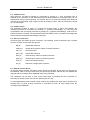
CONTENTS
1
INTRODUCTION ....................................................................................... 1
1.1
1.2
2
INTERFACE .............................................................................................. 1
2.1
2.2
2.3
2.4
2.5
2.6
3
GENERAL ......................................................................................... 1
SCRIPTS .......................................................................................... 1
CONNECTION ................................................................................... 1
CONFIGURATION ............................................................................... 1
COMMUNICATION .............................................................................. 2
PROMPT OPTION .............................................................................. 2
SPECIAL CHARACTERS ...................................................................... 2
REMOTE CONTROL STATE ................................................................. 2
INSTRUMENT COMMAND LANGUAGE .................................................. 3
3.1
SYNTAX ........................................................................................... 3
3.1.1 Commands ................................................................................................... 3
3.1.2 Arguments .................................................................................................... 3
3.1.3 Inline Text ..................................................................................................... 3
3.1.4 Comments .................................................................................................... 3
3.2
INSTRUMENT REPLIES ....................................................................... 4
3.2.1 Field Separators ........................................................................................... 4
3.2.2 Output Formats............................................................................................. 4
3.3
COMMAND EXECUTION ...................................................................... 4
3.3.1 Command Mode ........................................................................................... 4
3.3.2 Script Mode .................................................................................................. 4
3.3.3 Aborting Execution ....................................................................................... 5
4
COMMAND SET SUMMARY .................................................................... 6
5
SRG-2CE COMPATIBILITY .................................................................... 10
6
COMMAND REFERENCE....................................................................... 11
7
MESSAGES............................................................................................. 53
7.1
7.2
8
SCRIPT ERRORS ............................................................................. 53
RUN-TIME ERRORS ........................................................................ 54
APPENDIX .............................................................................................. 57
8.1
8.2
8.3
8.4
CONTROL DISPLAYS ........................................................................ 57
MEASUREMENT MODES .................................................................... 58
DATA SETS ..................................................................................... 58
SETUP ........................................................................................... 59
RS 232 - INTERFACE
SRG-3
1 INTRODUCTION
1.1 GENERAL
Remote control via the serial interface enables full access to all instrument resources and in
addition provides a set of functions not available in manual operation. The interface is designed to
be directly compatible to a personal computer serial port (COMx).
1.2 SCRIPTS
A powerful feature of the SRG-3 is the support of scripting. The instrument may be fully scriptcontrolled, freeing the user from the burden of writing dialog programs. Scripts may be prepared
using a normal text editor and then transmitted to the instrument by a simple terminal utility
program which in turn logs the instrument replies. A number of formatting options allow logged data
to be conveniently imported into spreadsheets. A learn script feature is included (see command
LRN) to assist the user in writing his own scripts for instrument setup.
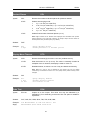
2 INTERFACE
2.1 CONNECTION
To connect the SRG-3 to a personal computer serial port, a 9-way extension cable (male to female)
is required. A null modem cable will not work. The table below shows the pin assignment of the
SRG-3 RS-232 connector (female). Note that only pins 2, 3 and 5 are used, the other pins are not
connected.
Terminal
Function
1
not connected
2
RXD – data out
3
TXD – data in
4
not connected
5
GND
6
not connected
7
not connected
8
not connected
9
not connected
2.2 CONFIGURATION
The SRG-3 may operate at 1200, 2400, 4800, 9600 (default) and 19200 baud. To change the
default setting, open parameter Baud in menu 13.1 and select the desired baud rate.
The computer interface must be configured for the same baud rate, 8 data bits, no parity, one stop
bit, no handshake.
1
RS 232 - INTERFACE
SRG-3
2.3 COMMUNICATION
After power-up, the SRG-3 prompts for commands by sending a '>' (62). Command input is
buffered up to a maximum of 128 characters and must be terminated by a carriage return (13). An
adjacent line feed (10) will be ignored. On receiving the CR, command processing starts. When all
commands are processed, reply output is closed by emitting a CRLF, then the instrument prompts
for new commands.
2.4 PROMPT OPTION
The parameter Prompt in menu 13.1 controls the prompt option. If set to Std (default), the
instrument prompts for commands by emitting a '>' (positive acknowledge), or, if an error was
encountered in the commands processed, by emitting a '?' (negative acknowledge). If set to Off, no
prompt character is emitted. The parameters Ackn and Nack in menu 13.2 allow free assignment
of the positive and negative acknowledge characters.
2.5 SPECIAL CHARACTERS
Incoming bytes are treated as 8-bit characters. The following control characters have a special
function, all other control codes are ignored:
BS (8)
deletes last character
CAN (24)
deletes all characters / aborts command execution
CR (13)
terminates input
DEL (127)
deletes last character
EOT (4)
discards input / aborts command execution
ESC (27)
discards input / aborts command execution
ETX (3)
aborts command execution
HT (9)
treated as a single space character
2.6 REMOTE CONTROL STATE
On the first valid command, the SRG-3 enters remote control state, forces menu 0.0 and turns on
the REMOTE LED. In remote control state, the control keys ENTER, ON and OFF are disabled and
respond with the message Key disabled! when being activated.
The instrument can be reset to local control state either by sending the RTL command, or,
manually, by selecting menu 5.0 and then pressing the OFF key.
In critical applications where manual control must be fully disabled, the keys may be locked out by
sending the LLO (local lockout) command. In local-lockout mode, all keys respond with the
message Keys disabled!.
2
RS 232 - INTERFACE
SRG-3
3 INSTRUMENT COMMAND LANGUAGE
3.1 SYNTAX
3.1.1 Commands
Command mnemonics are not case-sensitive and must be delimited by spaces or tabs. Redundant
delimiters are ignored. Multiple commands may be written on a single line.
Example:
amu vis tco
3.1.2 Arguments
Arguments (required or optional) must precede the command (postfix notation) and must be
delimited by spaces or tabs. Redundant delimiters are ignored.
Example:
2008 10 16 dat
Optional arguments determine the type of operation. If the argument is omitted, the command is a
read function and sends a reply. If the argument is present, the command is a write operator.
Example:
20 mti
mti
'sets measure time to 20s
'queries measure time
Integer arguments (n) are accepted in free format but must not contain a decimal point or an
exponent character (E). Integers may be also entered as hex numbers if prefixed by dollar sign ($).
Characters are not case-sensitive.
Example:
0 123 -1 $0D
Real arguments (x) are accepted in free format. Exponent characters are not case-sensitive.
Example:
123.45 10 -0.025 3.8e-5 -1 456.7E+00
String arguments (str) must be enclosed in double quotes ("). A string may be empty.
Example:
"UF6" ""
3.1.3 Inline Text
Inline text (txt) follows the ECH command and may contain any character except backslash (\)
which is treated as a delimiter. If not delimited by a backslash, the text extends to the end of line.
Example:
ech Ambient temperature [°C]\ in2
3.1.4 Comments
Script text starting with a quotation mark (‘) is treated as a comment and skipped up to the
matching unquote or to the end of line.
Example:
8 gas 'Uranium hexafluoride
'Ball diameter[mm]' 4.5 dia
3
RS 232 - INTERFACE
SRG-3
3.2 INSTRUMENT REPLIES
3.2.1 Field Separators
Numbers and labels are padded with a space character to separate the output fields when
commands are threaded.
Example:
Reply:
ech #\ num tim val ulb
#122 13:56:07 3.4567E-05 mbar
3.2.2 Output Formats
Integer numbers are returned in free format. Positive numbers have no sign holder.
Example:
0 123 -1
Real numbers are returned in scientific format with four decimal places (may be changed using the
FMT command). Positive numbers are preceded by a space.
Example:
1.2345E+02
-2.5000E-02
3.8000E-05
Strings are returned without delimiters to enable concatenation. If delimiting is required, quotation
marks may be added using the QUO and UNQ commands.
Example:
mbar User8 'SRG-3 V1.0.4 #500307 '
3.3 COMMAND EXECUTION
3.3.1 Command Mode
Interactive dialog runs in command mode (see also CMD). A number of commands (PRT, RST,
STA, STP) start a background task and then terminate immediately, so other things can be done
before the task is finished. The completion can be checked by polling the status (commands STS,
RCS). This is the default mode after power-up or reset.
3.3.2 Script Mode
In script mode (see also SCR), all commands execute in foreground and remain busy until their
task is finished. This ensures correct command sequencing. In case of premature termination due
to an error message, all succeeding commands are discarded until a CMD statement is processed,
which exits script mode and causes command execution to be resumed. In this way, the part of the
script that may be rendered pointless by the unsuccessful step will be skipped. Entering script
mode also enables talkative messages, so error messages will be included in the output log (see
also MSG).
4
RS 232 - INTERFACE
Example:
scr
'enter script mode
0 msg
'silent messages here
2 use
'recall setup #2
ech Date \ dat
'show date
ech Setup #\ use ech from \ sdt 'show setup used
ech Time
Press[\ ulb ech ]\
'show column titles
sta
'start measurement
5 rpt nxt tim val
'log 5 readings
stp
'stop rotor
cmd
'exit script mode, resume command
execution
msg
'show if successful
Reply:
Date 2008-10-16
Setup #2 from 2008-10-15
Time
Press[mbar ]
15:23:10 2.4530E-04
15:23:20 2.4531E-04
15:23:30 2.4531E-04
15:23:40 2.4532E-04
15:23:50 2.4531E-04
No message
SRG-3
3.3.3 Aborting Execution
Repeat loops (RPT), delays (DLY) and statements synchronizing with events (NXT) may be
aborted any time by sending one of the codes ESC (27), ETX (3), EOT (4) or CAN (24). The
command line being processed will then be discarded and the instrument returns to command
mode.
5
RS 232 - INTERFACE
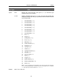
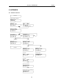
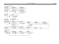
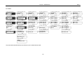
4 COMMAND SET SUMMARY
Legend
Symbol
[]
()
0 1..
c
file
hms
i
n
str
txt
x
ymd
Explanation
Optional argument. If present, command is a write operator.
Conditional reply, sent if command is a read function.
Fixed argument denoting a command option
Ascii code
Text file
Hours, minutes, seconds
Channel index
Integer number
String
Inline text
Real number
Year, month, day
Gas Parameters
Argum
Cmd
[x]
AMU
[n]
GAS
[x]
TCO
[x]
TMP
[x]
VIS
User Gas Definitions
Argum
Cmd
n
GLB
"str" n
GLB
USR
n
USR
0
USR
Sensor Parameters
Argum
Cmd
[x]
ACC
[n]
AUT
[n]
BGA
[x]
DEN
[x]
DIA
[x]
LSP
[x]
MTI
[x]
OFS
[n]
SPC
[x]
USP
Readout Settings
Argum
Cmd
ymd
DAT
[n]
DPL
[n]
DTO
[n]
OPT
hms
TIM
[n]
TSC
[n]
UNT
Reply
(x)
(n)
(x)
(x)
(x)
Description
Atomic mass units
Gas type
Temperature coefficient of viscosity
Temperature
Viscosity
Reply
str
Description
Query gas label
Assign user-defined gas label
List user definitions
Save as user gas type
Reset user definitions
file
Reply
(x)
(n)
(n)
(x)
(x)
(x)
(x)
(x)
(n)
(x)
Description
Accommodation factor
Automatic start
Background average
Ball density
Ball diameter
Lower speed limit
Measure time
Zero offset
Speed control mode
Upper speed limit
Reply
Description
Set date
Decimal places of pressure readout
Menu timeout
SI option
Set time
Temperature scale
Measurement unit
(n)
(n)
(n)
(n)
(n)
6
SRG-3
RS 232 - INTERFACE
Printer Settings
Argum
Cmd
[n]
CNT
[n]
PDA
[n]
PEJ
[n]
PFT
[n]
PHD
[n]
PIN
[n]
PPT
Reply
(n)
(n)
(n)
(n)
(n)
(n)
(n)
Description
Maximum count
Printout data option
Page eject option
Printout footer option
Printout header option
Printing interval
Printer port
Output Configuration
Argum
Cmd
[x]
AFS
[x]
ASP
[x]
HS1
[x]
HS2
[x]
SP1
[x]
SP2
Reply
(x)
(x)
(x)
(x)
(x)
(x)
Description
Analog output full scale
Analog output span
SP1 hysteresis
SP2 hysteresis
SP1 trip point
SP2 trip point
Auxiliary Input Configuration
Argum
Cmd
Reply
[n]
AM1
(n)
[n]
AM2
(n)
[x]
AO1
(x)
[x]
AO2
(x)
[n]
APW
(n)
[x]
AS1
(x)
[x]
AS2
(x)
Description
Auxiliary channel 1 mode
Auxiliary channel 2 mode
Auxiliary channel 1 offset
Auxiliary channel 2 offset
Auxiliary channels power supply
Auxiliary channel 1 scale factor
Auxiliary channel 2 scale factor
Serial Comm Settings
Argum
Cmd
Reply
[n]
BDR
(n)
[n]
PRO
(n)
c1 c2
PRO
Description
Baud rate
Prompt option
User-defined prompt characters
Setup File Management
Argum
Cmd
Reply
DEF
n
0
DEF
1
DEF
LRN
file
SDT
y-m-d h:m
n
STO
USE
n
n
USE
Description
Query default status
Clear default status
Default settings and set status
Send learn script
Timestamp of last setup change
Store current settings as setup file n
Query setup file used
Use setup file n
Sensor Control
Argum
Cmd
0
ARM
1
ARM
DMT
MNT
RST
SBY
STA
STP
Description
Disarm sensor control
Arm sensor control & perform sensor check
Dismount sensor
Mount sensor
Restart measurement
Standby mode
Start measurement
Stop sensor
Reply
7
SRG-3
RS 232 - INTERFACE
Measurement Readout
Argum
Cmd
DCR
IN1
IN2
PRS
REM
VAL
Zero Adjustment
Argum
Cmd
ZAD
1
ZAD
0
ZAD
Status & Messages
Argum
Cmd
MLG
0
MLG
MSG
0
MSG
1
MSG
OPH
RCS
STS
0
STS
Script Flow Control
Argum
Cmd
CMD
DLY
n
DLY
NXT
RPT
n
RPT
SCR
Output Formatting
Argum
Cmd
DAT
ECH txt
[n]
FMT
GLB
IDY
NUM
n
NUM
QUO
SDT
TIM
TLB
ULB
UNQ
Reply
x
x
x
x
x
x
Description
Deceleration rate (raw value)
Auxiliary channel 1
Auxiliary channel 2
Pressure (raw value)
Remaining time until next readout
Measured value
Reply
x
Description
Return zero adjust value
Do zero adjustment
Undo zero adjustment
Reply
file
Description
List logged messages
Erase logged messages
Read message
Clear pending message & set silent mode
Clear pending message & set talkative mode
Operating hours
Rotor control status
System status
Clear system status
str
n
n
n
Reply
Description
Command mode
Delay 600ms
Delay n seconds
Wait for next reading
Repeat until interrupted
Repeat n times
Script mode
Reply
y-m-d
txt
(n)
str
str
n
Description
Date string
Echo text
Real number output format
Gas label
Identify instrument
Return next number
Set number
Quote
Timestamp of last setup change
Time string
Temperature scale label
Unit label
Unquote
‘
y-m-d h:m
h:m:s
str
str
‘
8
SRG-3
RS 232 - INTERFACE
Front Panel & Power Control
Argum
Cmd
Reply
DIS
n
n
DIS
"str"
DIS
KEY
n
n
KEY
-n
KEY
LLO
PWR
n
1
PWR
0
PWR
SLK
n
1
SLK
0
SLK
RTL
Description
Query menu number
Display menu
Display string immediate
Return next key
Wait for key stroke
Push key
Local lock-out
Query power state
Power up (operating mode)
Power down (stand-by mode)
Query setup lock
Lock settings
Unlock settings
Return to local control
Printer Control
Argum
Cmd
PRT
n
PRT
0
PRT
"str"
PRT
Reply
n
Description
Query print status
Start print function
Stop print function
Print string immediate
Reply
Description
Set analog output voltage
Output override mode
Normal output mode
Query remote control outputs
Set remote control outputs
Query relay status
Set relays
Direct Output
Argum
Cmd
x
OUT
1
OVR
0
OVR
RCO
n
RCO
RLY
n
RLY
Diagnostics
Argum
Cmd
ACL
CAL
COR
DMP
1
DMP
2
DMP
IRS
ISP
RDS
RSP
SGL
TST
2
TST
1
TST
0
TST
n
n
Reply
x
x
x
x
x
x
x
n
x
x
n
Description
Acceleration factor
Calibration factor
Correction factor
Damping level A+B
Damping level A
Damping level B
Instrument reset
Initial speed
Rotor detection status
Rotational speed
Signal level
Query test mode
Perform signal statistics
Enter test mode
Exit test mode
9
SRG-3
RS 232 - INTERFACE
Head Adjustment
Argum
Cmd
HDA
0
HDA
1
HDA
2
HDA
9
HDA
Reply
y-m-d h:m
SRG-3
Description
Timestamp of last adjustment save
Reset adjustments
Levitation adjustment
Motor adjustment
Save adjustment in EEPROM
5 SRG-2CE COMPATIBILITY
The following SRG-2CE aliases are provided for compatibility:
Aliases
Argum
[n]
n
[x]
[x]
[x]
[x]
[n]
[n]
[n]
[x]
Cmd
CAP
CPT
DB1
DB2
DF1
DF2
FN1
FN2
HDO
SIN
Reply
(n)
(x)
(x)
(x)
(x)
(n)
(n)
(y-m-d h:m)
(x)
Description
Alias of BGA (n = 0..2)
Alias of ZAD (n = 0..2)
Alias of AO1
Alias of AO2
Alias of AS1
Alias of AS2
Alias of AM1
Alias of AM2
Alias of HDA
Alias of MTI
The following SRG-2CE commands are recognized but not supported:
Unsupported Commands
Argum
Cmd
Reply
BAT
0.0000E+00
[n]
DS1
(0)
[n]
DS2
(0)
[x]
RF1
(1.0000E+01)
[x]
RF2
(1.0000E+01)
Description
Battery voltage
Display span aux channel 1
Display span aux channel 2
Reference voltage aux channel 1
Reference voltage aux channel 2
The following commands are formally compatible, but differ from their SRG-2CE counterparts:
Command Differences
Argum
Cmd
Reply
"str"
DIS
[n]
KEY
(n)
7
PRT
RCS
Description
Flashing option not supported
Key codes not compatible
Histogram not supported
Meaning of status bits 3..0 slightly different
Note: The SRG-3 uses a dollar sign ($) as prefix for hexadecimal numbers, while the SRG-2CE
uses an ampersand (&).
10
RS 232 - INTERFACE
SRG-3
6 COMMAND REFERENCE
Accommodation Factor
Syntax:
ACC
Returns the accommodation factor.
x ACC
Enter the accommodation factor x (0.1 to 2).
Related:
DIA, DEN
Example:
acc
1.012 acc
'query accommodation factor
'change accommodation factor to 1.012
Acceleration Factor
Syntax:
ACC
ACL
ACL
Returns the acceleration factor [s-2A-2] used for speed control.
acl
'query acceleration factor
Related:
Example:
Analog Output Full Scale
Syntax:
AFS
AFS
Returns the analog output full scale value [unit].
x AFS
Enter the value for analog output full scale in the selected unit:
x = 10-5 to 103 Pa
x = 10-7 to 10 mbar
x = 7.5 •10-8 to 7.5 Torr
x = 10-8 to 0.1 s-1
Values entered in mbar or Torr are internally stored in Pa. The stored
value is not converted if the unit is changed to or from s-1. A zero
value forces the analog output to full scale (10V). The output voltage
VOUT for a measured value p is calculated as:
ASP=0: VOUT = 10V• p/AFS
ASP>0: VOUT = 10V • (1 + log(p/AFS)/ASP)
Related:
ASP, OUT, OVR
Example:
afs
2 unt
0.1 afs
'query analog output full scale
'select mbar
'set full scale to 0.1 mbar
11
RS 232 - INTERFACE
Auxiliary Channel 1 Mode
Syntax:
SRG-3
AM1
AM1
Returns the mode of auxiliary input channel 1.
n AM1
Selects the mode n of auxiliary input channel 1, determining the
presentation of measured values:
0
raw value [V]
1
temperature [tscal]
2
pressure [unit]
3
special (no unit)
If set to mode 1, aux channel 1 will supply the gas temperature,
thereby overriding the stored setting.
Related:
AO1, AS1, TMP, TSC, UNT
Example:
am1
1 am1
'query mode of aux channel 1
'set up channel 1 for temperature
Auxiliary Channel 2 Mode
Syntax:
AM2
AM2
Returns the mode of auxiliary input channel 2.
n AM2
Selects the mode n of auxiliary input channel 2, determining the
presentation of measured values:
0
raw value [V]
1
temperature [tscal]
2
pressure [unit]
3
special (no unit)
Related:
AO2, AS2, TMP, TSC, UNT
Example:
am2
2 am2
'query mode of aux channel 2
'set up channel 2 for pressure
Atomic Mass Units
Syntax:
AMU
AMU
Returns the mean molecular mass in u (atomic mass units).
x AMU
Enter the mean molecular mass x (1 to 1000 u) and reset the gas type
to 0 (User).
Related:
GAS, TCO, USR, VIS
Example:
amu
44.1 amu
'query molecular mass
'change molecular mass to 44.1 u
12
RS 232 - INTERFACE
Auxiliary Channel 1 Offset
Syntax:
SRG-3
AO1
AO1
Returns the offset of auxiliary input channel 1.
x AO1
Enter the offset x (-1E30 to +1E30) for channel 1. This value biases
the linear scaled input VIN1 (R displayed reading):
R = AS1 • VIN1 + AO1.
Related:
AM1, AS1, IN1
Example:
ao1
'query aux channel 1 offset
1 am1
101 as1
-0.21 ao1
'temperature input
'sensitivity 10 mV/K
'adjust zero (0°C)
Auxiliary Channel 2 Offset
Syntax:
AO2
AO2
Returns the offset of auxiliary input channel 2.
x AO2
Enter the offset x (-1E30 to +1E30) for channel 2. This value biases
the linear scaled input VIN2 (R displayed reading):
R = AS2 • VIN2 + AO2.
Related:
AM2, AS2, IN2
Example:
ao2
'query aux channel 2 offset
2 am2
'pressure input
0.1 as2
'full scale 1 Pa
-0.0002 ao2 'adjust zero
Auxiliary Power
Syntax:
APW
APW
Returns the auxiliary power setting:
0
1
+/-15V supply off
+/-15V supply on
1 APW
Turns the auxiliary power on.
0 APW
Turns the auxiliary power off.
apw
1 apw
'query aux power setting
'turn on power for aux channels 1 & 2
Related:
Example:
13
RS 232 - INTERFACE
Arm Sensor Control
Syntax:
ARM
ARM
Returns the state of the sensor control (0 = disarmed, 1 = armed).
0 ARM
Disarms the automatic sensor control. When the sensor is mounted,
nothing occurs.
1 ARM
Arms the automatic sensor control and performs a sensor check by
forcing the sensor to the lower and upper position. If present, the
sensor is levitated and measurement starts, depending on the AUT
setting. When the sensor is already mounted, nothing occurs.
Related:
MNT, STA
Example:
arm
'query arm state
dmt
0 arm
'drop sensor
'disarm sensor control
Auxiliary Channel 1 Scale
Syntax:
SRG-3
AS1
AS1
Returns the scale factor of auxiliary input channel 1.
x AS1
Enter the scale factor x (1E-30 to 1E30) for channel 1. In temperature
mode (AM1 = 1), the factor must be entered in K/V; in pressure mode
(AM1 = 2), the factor must be entered in Pa/V. The displayed value R
for a measured input voltage VIN1 is calculated as:
R = AS1 • VIN1 + AO1
Related:
AM1, AO1, IN1
Example:
as1
'query scale factor of aux channel 1
3 unt
2 am1
133.33 as1
0 ao1
'select Torr
'chan 1 pressure input
'scale 133.33 Pa/V = 10 Torr full scale
'zero offset
Auxiliary Channel 2 Scale
Syntax:
AS2
AS2
Returns the scale factor of auxiliary input channel 2.
x AS2
Enter the scale factor x (1E-30 to 1E30) for channel 2. In temperature
mode (AM1 = 1), the factor must be entered in K/V; in pressure mode
(AM1 = 2), the factor must be entered in Pa/V. The displayed value R
for a measured input voltage VIN2 is calculated as:
R = AS2 • VIN2 + AO2
Related:
AM2, AO2, IN2
14
RS 232 - INTERFACE
Example:
as2
'query scale factor of aux channel 2
1 unt
2 am2
1 as2
'select Pa
'chan 2 pressure input
'1 Pa/V = 10 Pa full scale
Analog Output Span
Syntax:
SRG-3
ASP
ASP
Returns the analog output span.
0 ASP
Selects linear scale.
n ASP
Selects logarithmic scale spanning n decades (1 to 10).
The output voltage VOUT for a measured value p is calculated as:
ASP=0: VOUT = 10V • p/AFS
ASP>0: VOUT = 10V • (1 + log(p/AFS)/ASP)
Related:
AFS
Example:
asp
0 asp
5 asp
Automatic Start
Syntax:
'query output span
'select linear output
'select log output (2 volt/decade)
AUT
AUT
Returns the automatic start mode.
0 AUT
Disables automatic start on power-up.
1 AUT
Enables automatic start on power-up. Note that speed control should
also be set to an automatic mode to allow continuous measurement
(see SPC).
Related:
SPC
Example:
aut
1 aut
'query automatic start mode
'enable automatic start
15
RS 232 - INTERFACE
Background Average
Syntax:
SRG-3
BGA
BGA
Returns the selected background average span.
n BGA
Sets the background average span to n readings (n = 0..50). If n < 2,
no averaging is performed and the current reading is used for zero
adjustment.
Note: The moving background average is the mean value of the last n pressure (PRS)
or DCR readings, depending on the selected unit. This mean value is used for zero
adjustment by the command ZAD. Changing the unit will flush the buffer and reset the
average value.
Related:
OFS, ZAD
Example:
bga
30 bga
'query backgound average
'set span to 30 readings
Baud Rate
Syntax:
BDR
BDR
Returns the baud rate setting.
n BDR
Selects baud rate n (1200, 2400, 4800, 9600, 19200).
Note: The baud rate returned is the stored value and may differ from the actual baud
rate. Changing the baud rate remotely causes the new setting to be stored, but
switching of the baud rate is deferred until the next instrument reset. If the baud rate is
to be changed immediately, an IRS command must follow the BDR on the same line.
Related:
Example:
bdr
19200 bdr irs
Calibration Factor
Syntax:
CAL
'query stored baud rate
'go to 19200 baud
CAL
Returns the calibration factor [unit s] for the selected unit. If DCR is
selected (unit = 0), the value is returned in Pa•s.
Note: The calibration factor is calculated as: CAL = PRS / (DCR • COR).
Related:
COR, DCR, PRS
Example:
1 unt
'select Pa
10 gas
'select Argon
nxt cal
'query calibration factor of next reading
2.1455E+03
Reply:
16
RS 232 - INTERFACE
Command Mode
CMD
Syntax:
CMD
Related:
SCR
Example:
scr
0 msg
2 use
ech Date \ dat
ech Setup #\ use ech
sta
30 rpt nxt tim val
stp
cmd
ech Message: \ msg
Exits script mode (see section 3.3.2), selects silent messages and
resumes command execution.
Maximum Count
Syntax:
SRG-3
'enter script mode
'silent messages
'recall setup #2
'show date
from \ sdt 'show setup used
'start measurement
'log 30 readings
'stop rotor
'exit script mode, resume cmd execution
'show possible message
CNT
CNT
Returns the maximum count for continuous printing.
n CNT
Enter maximum count n (0 to 100) for continuous printing. On
reaching the maximum count, continuous printing stops and the footer
selected by the PFT option will be added to the printout. A zero count
selects printing to be unlimited.
Note: The mode is also affected by the printing interval: If the interval is ≤ 120 min, the
CNT value determines the total number of readings to be printed. If the interval is > 120
min, the CNT value specifies a set of consecutive readings to be printed each time the
interval expires (see also PIN). For example, setting CNT = 10 and PIN = 60 will result
in a total of 10 readings being printed at one hour intervals, while setting PIN = 180 will
result in 10 consecutive readings printed every 3 hours until stopped by operator action.
Related:
PFT, PIN, PRT
Example:
cnt
30 cnt
'query maximum count
'set count to 30
Correction Factor
COR
Syntax:
COR
Returns the DCR correction factor linearizing the current pressure
reading. The correction factor is calculated as: COR = PRS / (DCR •
CAL).
Related:
CAL, DCR, PRS
Example:
Reply:
nxt val cor 'query value and correction factor of next reading
1.5791E-03 1.0014E+00
17
RS 232 - INTERFACE
Date
Syntax:
DAT
DAT
Returns a string with the current date formatted yyyy-mm-dd.
y m d DAT
Sets the date to year y (2000 to 2099), month m (1 to 12) and day d (1
to 31).
Related:
SDT, TIM
Example:
Reply:
ech Measurement #\ num ech dated \ dat
Measurement #122 dated 2008-10-08
Example:
2008 10 12 dat
Deceleration Rate
Syntax:
SRG-3
DCR
'set date to 2008-10-12
DCR
Returns the measured deceleration rate [s-1] and clears system status
bit 4 (Data available).
Note: DCR always returns the raw, ie non-offset, value. To read the zero-adjusted
deceleration rate, the VAL command must be used.
Related:
STS, CPT, VAL
Example:
1 unt
'select Pa
rpt nxt dcr prs 'log pressure vs DCR
Default Settings
Syntax:
DEF
DEF
Returns the value of status bit 6 (Backup failed/Setup defaulted).
0 DEF
Clears status bit 6 (Backup failed/Setup defaulted).
1 DEF
Defaults all settings, resets all user gas definitions, unlocks the setup
and sets status bit 6 (Backup failed/Setup defaulted). The instrument
is reset to the factory settings.
Related:
STS
Example:
def
1 def
'check if setup has been defaulted
'restore the default settings
18
RS 232 - INTERFACE
Ball Density
Syntax:
SRG-3
DEN
DEN
Returns the stored rotor ball density [g cm-3].
x DEN
Enter the rotor ball density x (6 to 10 g cm-3)¹.
Note 1: This is a formal range for the density value. There may be tighter limitations
imposed by the instrument hardware.
Related:
ACC, DIA
Example:
den
7.87 den
Ball Diameter
Syntax:
'query ball density
'change ball density to 7.87 g/cm3
DIA
DIA
Returns the stored rotor ball diameter [mm].
x DIA
Enter the rotor ball diameter x (1 to 6 mm)¹.
Note 1: This is a formal range for the diameter value. There may be tighter limitations
imposed by the instrument hardware.
Related:
ACC, DEN
Example:
dia
4.7 dia
Display Control
Syntax:
'query ball diameter
'change ball diameter to 4.7 mm
DIS
DIS
Returns the number of the menu displayed. The number returned
corresponds to the menu number times 10, eg 60 stands for menu
6.0. To maintain compatibility with the SRG-2CE display options, there
are two exceptions: 3 is returned instead of 10 and 6 is returned
instead of 40.
n DIS
Selects menu n (0 to 150), n being the menu number times 10. To
maintain compatibility with the SRG-2CE display options, there are
two additions: n = 3 to 5 selects menu 1.0 and n = 6 selects menu 4.0.
"str" DIS
Displays str immediate. The string may be up to 32 characters. An
empty string blanks the display. The menu number changes to 9.
Related:
KEY
Example:
dis
2 dis
3 dis
10 dis
"Test:
'query menu number
'show menu 0.2 (aux channel 2)
'show menu 1.0 (DCR)
'same as above
ENTER" dis
19
'occupies 2 rows
RS 232 - INTERFACE
Delay
Syntax:
DLY
DLY
Delays command processing for approx. 600 ms.
n DLY
Delays command processing for n seconds (1 to 3600).
Related:
DIS
Example:
rpt in1 60 dly
Damping Level
Syntax:
SRG-3
'log aux channel 1 once a minute
DMP
DMP
Returns the output level [dB] of the sensor damping channels A+B.
1 DMP
Returns the output level [dB] of damping channel A.
2 DMP
Returns the output level [dB] of damping channel B.
Note: The value may serve as an indication of the level of mechanical interference the
gauge head is exposed to.
Related:
SGL
Example:
rpt dmp 1 dly
Dismount Sensor
Syntax:
DMT
'check damping level every second
DMT
Turns off the levitation control, causing the sensor to drop.
Caution: DMT should only be commanded when the sensor is idle!
Related:
MNT, STP
Example:
scr
stp dmt
cmd
'execute in foreground
'stop rotor and dismount
'exit foreground
20
RS 232 - INTERFACE
Decimal Places
Syntax:
DPL
DPL
Returns the number of decimal places for pressure readout.
0 DPL
Selects auto-ranging mode:
n DPL
SRG-3
1
if p < 10-3 Pa (10-5 mbar/Torr)
2
if 10-3 Pa (10-5 mbar/Torr) ≤ p < 10-2 Pa (10-4 mbar/Torr)
3
if 10-2 Pa (10-4 mbar/Torr) ≤ p < 10-1 Pa (10-3 mbar/Torr)
4
if p ≥ 10-1 Pa (10-3 mbar/Torr)
Selects fixed number of decimal places (1 to 4).
Note: Digits rounded off are blanked when displayed and zero-filled when printed.
Values returned by VAL and PRS, however, are always output with the number of
decimal places set by the FMT option (4 by default).
Related:
FMT
Example:
dpl
3 dpl
Display Menu Timeout
Syntax:
'query decimal places
'round pressure to 3 decimal places
DTO
DTO
Returns the timeout [s] for menus 1.0 to 6.4 (readout menus).
n DTO
Sets the timeout to n s (5 to 60). The value is internally rounded to
multiples of 5s. On timeout, the display is reset to menu 0.0.
0 DTO
Disables timeout, so menus 1.0 to 6.4 may be viewed continuously.
Note: Menus 0.1 and 0.2 are not affected by the timeout and may be viewed
continuously. The timeout for menus 7.0 to 13.2 (setup menus) is 60s and may not be
changed.
Related:
DIS
Example:
dto
0 dto
30 dto
Echo Text
'query display timeout
'disable display timeout
'set timeout to 30s
ECH
Syntax:
ECH txt
Copies txt to the output. This inline text may be delimited by a
backslash (\) if not extending to the end of line. No space is added for
separation.
Related:
DAT, GLB, IDY, NUM, QUO, TIM, TLB, ULB, UNQ
Example:
Reply:
ech Measurement #\ num ech dated \ dat
Measurement #122 dated 2008-10-12
21
RS 232 - INTERFACE
Example:
Reply:
ech Pressure[\ ulb ech ]
Pressure[mbar ]
Example:
Reply:
quo ech Temperature[\ tlb ech ] unq tmp ech tmp
'Temperature[K ]' 2.9871E+02 tmp
Real Number Format
Syntax:
SRG-3
FMT
FMT
Returns the decimal places selected for real number output format.
n FMT
Selects n (1 to 6) decimal places for real number output format. The
value applies to all real numbers transmitted by the instrument. The
format setting is not saved. On reset, the format defaults to 4 places.
Related:
DPL
Example:
fmt
'query format
5 fmt
'output real with 5 places
rpt nxt val 'log readings
Reply:
2.45308E-04
2.45310E-04
2.45311E-04
...
22
RS 232 - INTERFACE
Gas Type
Syntax:
SRG-3
GAS
GAS
Returns the current gas type. Gas type 0 (User) is returned if gas
properties have been modified.1
n GAS
Selects predefined gas type n (1 to 25). The gas type numbers are
assigned as follows (the strings in parentheses are the labels returned
by command GLB):
1
user-definable (Usr1)
2
user-definable (Usr2)
3
user-definable (Usr3)
4
user-definable (Usr4)
5
user-definable (Usr5)
6
user-definable (Usr6)
7
user-definable (Usr7)
8
user-definable (Usr8)
9
Air (Air)
10
Argon (Ar)
11
Acethylene (C2H2)
12
Freon-14 (CF4)
13
Methane (CH4)
14
Carbon dioxide (CO2)
15
Deuterium (D2)
16
Hydrogen (H2)
17
Helium (He)
18
Hydrogen fluoride (HF)
19
Nitrogen (N2)
20
Nitrous oxide (N2O)
21
Neon (Ne)
22
Oxygen (O2)
23
Sulfur dioxide (SO2)
24
Sulfur hexafluoride (SF6)
25
Xenon (Xe)
Note 1: If any gas property is set (see AMU, TCO, VIS), the gas type is reset to 0
(User). As the gas parameters are stored as part of the setup file, up to 15 different
User gas types may be used in addition to Usr1 to Usr8.
Related:
AMU, TCO, USR, VIS
23
RS 232 - INTERFACE
Example:
gas
8 gas
20 gas
'query gas type
'select Usr8
'select N2
Gas Type Label
Syntax:
GLB
GLB
Returns a string identifying the selected gas type (see GAS). If the
gas type is 0, the string "User" is returned.
n GLB
Returns the identifier of gas type n (1 to 25).
"str" n GLB
Sets the identifier of user-definable gas type n (1 to 8) to str. If str is
longer than 4 characters, the first 4 characters are used. The new
label will replace the standard label Usrn.
Related:
ECH, GAS, QUO, UNQ
Example:
Reply:
ech Gas: \ glb
Gas: CH4
Example:
Reply:
14 glb
CO2
Example:
"UF6" 3 glb 'rename Usr3 to UF6
Head Adjust
Syntax:
SRG-3
'get label of gas type 14
HDA
HDA
Returns a string with the timestamp of the last head adjustment save.
If no adjustment has been done by the user, this is the timestamp of
the factory initialization.
0 HDA
Resets the adjustment to default values.1
1 HDA
Adjusts levitation control by zeroing the sensor detection voltage. The
sensor has to be removed for this procedure.1
2 HDA
Optimizes speed control by tuning the motor to its resonant frequency.
The drive frequency is swept from high to low values until the drive
current peak is located. The command runs in foreground.1
9 HDA
Saves the adjusted parameters in EEPROM and adds the timestamp.
Unless 9 HDO is executed, the adjustment remains voltatile and the
previously saved parameters are restored on instrument initialization.
Note 1: The results are not automatically saved in EEPROM memory. To make the
adjustment permanent, a subsequent command 9 HDA is required. If the operation is
attempted while the sensor is mounted, script error 99 occurs.
Related:
24
RS 232 - INTERFACE
Example:
hda
0 hda
'query date of last adjustment
'reset adjustment
Example:
1 hda
2 hda
9 hda
'adjust levitation
'tune motor
'save adjustment
Setpoint 1 Hysteresis
Syntax:
SRG-3
HS1
HS1
Returns the hysteresis of setpoint 1.
x HS1
Enter the hysteresis x (-0.5 to 1) for setpoint 1. The sign of the value
determines the hysteresis mode:
HS1<0: relay activated at p > SP1 and released at p < (1+HS1) • SP1
HS1>0: relay activated at p > (1+HS1) • SP1 and released at p < SP1
Related:
SP1
Example:
hs1
'query hysteresis of SP1
3 unt
1.e-3 sp1
-0.05 hs1
'select Torr
'change SP1 level to 1.E-3 Torr
'SP1 is activated at p > 1.E-3 Torr
'and released at p < 9.5E-4 Torr
Setpoint 2 Hysteresis
Syntax:
HS2
HS2
Returns the hysteresis of setpoint 2.
x HS2
Enter the hysteresis x (-0.5 to 1) for setpoint 2. The sign of the value
determines the hysteresis mode:
HS2<0: relay activated at p > SP2 and released at p < (1+HS2) • SP2
HS2>0: relay activated at p > (1+HS2) • SP2 and released at p < SP2
Related:
SP2
Example:
hs2
'query hysteresis of SP2
3 unt
1.e-3 sp2
-0.05 hs2
'select Torr
'change SP2 level to 1.E-3 Torr
'SP2 is activated at p > 1.E-3 Torr
'and released at p < 9.5E-4 Torr
25
RS 232 - INTERFACE
Identify
IDY
Syntax:
IDY
Related:
ECH, QUO, UNQ
Example:
Reply:
quo idy unq
'SRG-3 V1.0.4 S/N G500307G40 '
Returns a string identifying the instrument stating model, firmware
version and serial number.
Auxiliary Channel 1 Input
Syntax:
IN1
Related:
AM1, AO1, AS1
Example:
in1 in2
Syntax:
IN2
Related:
AM2, AO2, AS2
Example:
in1 in2
Instrument Reset
IRS
IN1
Returns the value of auxiliary input channel 1, scaled according to the
selected mode (see AM1, AO1, AS1).
'read aux channel values
Auxiliary Channel 2 Input
Syntax:
SRG-3
IN2
Returns the value of auxiliary input channel 2, scaled according to the
selected mode (see AM2, AO2, AS2).
'read aux channel values
IRS
Resets the instrument and performs the power-up initialization
procedure.
Caution: IRS turns off the gauge head power immediately!
Related:
AUT, BDR
Example:
0 pwr
irs
Initial Speed
Syntax:
ISP
Related:
RSP, USP
'power down sensor
'reset instrument
ISP
Returns the initial sensor speed, ie the sensor speed after the last
acceleration, in Hz.
26
RS 232 - INTERFACE
Example:
isp
'query initial speed
Wait for Key Stroke
Syntax:
SRG-3
KEY
KEY
Waits for a key stroke and returns the code.
n KEY
Wait for the key n to be pressed:
n
Key
1
POWER
2
ON
3
OFF
4
ESC
5
ENTER
6
½
7
¾
8
»
9
¼
-n KEY
Push key, ie perform action of key n. The disabled keys POWER, ON,
OFF and ENTER will be enabled first.
0 KEY
Disable keys again.
While waiting for operator response, the REMOTE LED keeps flashing
to indicate that key action is requested by remote control.
Related:
DIS
Example:
"Press any key:" dis 'announce test
rpt key
'read key codes
"Continue with
ENTER:" dis
5 key
'wait for key
71 dis
-9 key
Local Lock Out
Syntax:
LLO
Related:
RTL
'inform operator
'show gas setup menu
'set cursor on gas selection
LLO
Locks out local control by disabling the manual return feature in menu
5.0. After execution of LLO, return to local control is only possible by
sending the RTL or IRS command, or by switching the instrument off
and on again.
27
RS 232 - INTERFACE
Example:
llo
...
rtl
Learn Script
Syntax:
LRN
Related:
STO, USE
SRG-3
'disable local control
'perform critical operations
'enable local control
LRN
Returns a script file restoring the currently active settings when sent
back to the instrument. The script includes a header identifying the
instrument and the setup file being transmitted. Each setting is
commented. The learn script may serve as a template to set up the
instrument, or may be used for backup and/or documentation
purpose.
28
RS 232 - INTERFACE
Example:
Reply:
lrn
'download settings
'Date 2008-10-08 13:27:42 '
'SRG-3 V1.0.4 S/N G500307G40'
'Setup 0 from 2008-10-08 12:25 '
'Readout:'
'Display unit' 1 unt
'Temperature scale' 0 tsc
'Decimal places' 3 dpl
'Display timeout [s]' 0 dto
'Gas:'
'Name: Ar'
'Select gas' 10 gas
'Temperature [K]' 2.9315E+02 tmp
'Sensor:'
'Accommodation' 1.0000E+00 acc
'Measure time [s]' 3.0000E+00 mti
'Ball diameter [mm]' 4.5000E+00 dia
'Ball density [g/cm^3]' 7.7000E+00 den
'Upper speed limit [Hz]' 4.4000E+02 usp
'Lower speed limit [Hz]' 4.3000E+02 lsp
'Automatic start' 1 aut
'Speed control mode' 1 spc
'Background average' 10 bga
'Zero offset [Pa]' 0.0000E+00 ofs
'Printout:'
'Maximum count' 10 cnt
'Print interval' 0 pin
'Printout header' 1 phd
'Printout footer' 1 pft
'Printout data' 0 pda
'Printer port' 1 ppt
'Page eject' 1 pej
'Outputs:'
'Setp 1 [Pa]' 1.0000E+00 sp1
'Setp 2 [Pa]' 1.0000E+00 sp2
'Hyst 1' -5.0000E-02 hs1
'Hyst 2' -5.0000E-02 hs2
'Analog full scale [Pa]' 1.0000E+00 afs
'Analog span' 5 asp
'Aux inputs:'
'Mode 1' 2 am1
'Mode 2' 0 am2
'Scale 1' 1.0000E+04 as1
'Scale 2' 1.0000E+00 as2
'Offset 1' 0.0000E+00 ao1
'Offset 2' 0.0000E+00 ao2
'Aux power' 1 apw
Example:
lrn
1 use lrn
2 use lrn
...
'active settings
'stored setup files...
29
SRG-3
RS 232 - INTERFACE
Lower Speed Limit
Syntax:
SRG-3
LSP
LSP
Returns the actual¹ lower speed limit [Hz].
x LSP
Enter the lower operational speed limit x (405 to 805 Hz). The value is
clipped to 5 Hz below the upper speed limit.
Note 1: When operating in speed control mode 2, the actual speed limits may be
dynamically extended to meet the specified sampling interval. When changing USP, the
LSP value will be adjusted automatically to retain the speed window size.
Related:
MTI, SPC, USP
Example:
lsp
'query lower speed limit
450 usp 430 lsp 'select speed range 450..430 Hz
Message Log
Syntax:
MLG
MLG
Returns the message log file. The message log contains the last 63
messages with their timestamps. If the message log is empty, a nomessages statement with the actual timestamp is returned (see
example).
0 MLG
Erases the logged messages.
Related:
MSG
Example:
Reply:
mlg
'examine message log
2008-10-12 08:17 Err 33: Controlling speed failed
2008-10-12 12:45 Err 34: Bad signal level
2008-10-12 14:38 Err 22: Mounting rotor failed
Example:
0 mlg
'flush message log
mlg
'read message log
2008-10-12 11:43 No messages
Reply:
Mount Rotor
Syntax:
MNT
MNT
Turns on the magnetic bearing causing the sensor to levitate. The
sensor remains in idle mode (Idle). MNT runs in background. If the
rotor is already mounted, no action is taken.
Note: If armed (see ARM), the sensor is automatically mounted when it is detected
inside the air gap of the magnetic bearing.
Related:
ARM, DMT, RCS, SBY, STA
Example:
scr
'execute in foreground
'Exercise levitation:
3 rpt mnt 2 dly dmt 2 dly
...
30
RS 232 - INTERFACE
Message
Syntax:
SRG-3
MSG
MSG
Returns the message waiting in the message buffer and clears system
status flag 5 (Message). If the buffer is empty, the string "No
message" is returned.
0 MSG
Selects silent messages (default) and clears system status flag 5,
flushing an old message. A new message will be buffered.
1 MSG
Selects talkative messages and clears system status flag 5, flushing
an old message. A new message will be transmitted.
Note: Messages are also logged in the message log file (see also MLG).
Related:
MLG, STS
Example:
Reply:
msg
'read silent message
Err 33: Controlling speed failed
Example:
0 msg
1 msg
'flush old message
'get new messages immediately
Measure Time
Syntax:
MTI
MTI
Returns the actual¹ measure time [s].
x MTI
Enter the measure time. The value x (5 to 60 s) is internally rounded
to tenths of seconds. If the interval is changed during measurement, a
reduction will take effect immediately, whereas an extension will be
deferred until the next measurement cycle.
Note 1: If not measuring, the stored value is returned. When operating in speed control
mode 1, the actual measure time may vary dynamically to meet the specified speed
limits.
Related:
LSP, SPC, USP
Example:
mti
5 mti
Numbering
Syntax:
'query measure time
'change measure time to 5 s
NUM
NUM
Returns the next consecutive number in unsigned format.
n NUM
Presets the number to n (0 to 4294967295). The next number
returned will be n+1.
Note: The command may be used to number the iterations of RPT, etc. The number
resets to 0 when the instrument is switched on.
Related:
RPT
31
RS 232 - INTERFACE
Example:
0 num
'clear number
rpt nxt num val 'log numbered readings
Reply:
1 2.4530E-04
2 2.4531E-04
3 2.4531E-04
...
Wait for Next Reading
Syntax:
NXT
SRG-3
NXT
Waits for system status bit 4 (Data available) to be asserted. The
status flag is not changed.
Note: If used inside a loop (RPT), the status flag must be cleared between iterations by
one of the commands VAL, PRS, DCR or 0 STS.
Related:
DCR, VAL, STS
Example:
0 sts
'begin with new status
rpt nxt val 'log measured values
Reply:
2.4530E-04
2.4533E-04
2.4531E-04
...
Zero Offset
Syntax:
OFS
OFS
Returns the zero offset [unit].
x OFS
Enter the zero offset in the selected unit:
x = 0 to 103 Pa
x = 0 to 10 mbar
x = 0 to 7.5 Torr
x = 0 to 10-3 s-1
Values entered in mbar or Torr are internally stored in Pa. The stored
value is not converted if the unit is changed to or from s-1.
Related:
UNT
Example:
ofs
'query offset
3 unt
2.321e-6 ofs
'select Torr
'enter zero offset 2.321E-6 Torr
Operating Hours
Syntax:
OPH
OPH
Returns the number of instrument operating hours.
Related:
32
RS 232 - INTERFACE
Example:
oph
'check operating hours
Instrument Options
Syntax:
SRG-3
OPT
OPT
Returns the selected instrument options.
1 OPT
Sets option 1 (SI only). The unit is forced to Pa and the temperature
scale is forced to K..
0 OPT
Resets options.
Note: With option 1 set, UNT does not accept values > 1 and TSC does not accept 1.
Related:
DEF, UNT
Example:
opt
1 opt
0 opt
'check instrument options
'force SI units
'reset instrument options
Analog Output
Syntax:
OUT
OUT
Returns the analog output voltage [V].
x OUT
Sets the analog output voltage to x (0 to 11V). The override mode
must be set or else the analog output will periodically be overwritten
by the measured value (see OVR).
Related:
AFS, ASP, OVR
Example:
out
1 ovr
10 out
Output Override
Syntax:
'compare with the actual output voltage
'set override mode
'force output to full scale
OVR
1 OVR
Sets output override mode. Analog output and relay switches may be
set directly by the OUT and RLY commands.
0 OVR
Resets output override mode. Analog output and relay switches are
automatically set by the measurement results.
Related:
OUT, RLY
Example:
1 ovr
10 out
'set override mode
'force output to full scale
33
RS 232 - INTERFACE
Printout Data
Syntax:
PDA
n PDA
PDA
Returns the printout data option:
0
standard (time & measured value)
1
auxiliary channel 1 & measured value
2
auxiliary channel 2 & measured value
3
time & setpoint status & measured value
Selects printout data option n (0 to 3). If enabled by the printout
header option (see also PHD), column titles as shown below will be
included, the tscal and unit holders being filled in by the respective
labels.
n
Column titles
0
Time
Time
Press[unit] or
DCR[1/s]
1
Aux1[V]
Aux1[tscal]
Aux1[unit]
Aux1[]
Press[unit] or
Press[unit] or
Press[unit] or
Press[unit]
2
Aux2[V]
Aux2[tscal]
Aux2[unit]
Aux2[]
Press[unit] or
Press[unit] or
Press[unit] or
Press[unit]
3
Time
Time
Related:
AM1, AM2, PHD, TSC, UNT
Example:
pda
0 pda
2 pda
Related:
PEJ
SP Press[unit] or
SP DCR[1/s]
'query printout data option
'select standard printout
'select logging of ain2
Page Eject
Syntax:
SRG-3
PEJ
Returns the automatic page eject option:
0
page eject disabled
1
page eject enabled
1 PEJ
Enables automatic page eject after printing. Print jobs are terminated
by sending a FF character (ASCII 12) to the parallel printer or a
double CLRF sequence to the serial printer.
0 PEJ
Disables automatic page eject. Print jobs are terminated by sending a
double CRLF sequence.
PRT
34
RS 232 - INTERFACE
Example:
pej
1 pej
'query page eject option
'enable page eject
Printout Footer
Syntax:
PFT
n PFT
SRG-3
PFT
Returns the printout footer option:
0
no footer
1
standard footer¹
2
count statement only
Selects the printout footer option n (0 to 2). The selected footer will be
added to the printout when continuous printing stops having reached
the maximum count or being terminated by operator action. The footer
will be omitted for a count < 2.
Note 1: For count > 1, the standard footer shows count and mean value. For count > 2,
the standard footer comprises count, mean value, maximum deviation, standard
deviation and mean standard deviation of the printed readings.
Related:
CNT, PHD
Example:
pft
0 pft
'query footer option
'no footer printed
Example:
1 pft
'standard footer
-----------------------Count
13
Mean value
1.8989E-03
Max. dev.
5.3000E-07
Std. dev.
3.4000E-07
Mean std.
9.3000E-08
Example:
2 pft
'count statement only
-----------------------Count
30
35
RS 232 - INTERFACE
Printout Header
Syntax:
PHD
n PHD
SRG-3
PHD
Returns the printout header option:
0
no header
1
standard header
2
column titles only
Selects the printout header option n (0 to 2).
Note: The printout number resets when the header option is entered, when the system
date is set (DAT command), and on start of the print function when date has changed
since the last printout.
Related:
PDA, PFT
Example:
phd
0 phd
'query header option
'no header printed
Example:
1 phd
'standard header
SRG-3 Vacuum Gauge 1.0.4
Setup 14 from 2008-10-10
Date 2008-10-13
#17
-----------------------Time
Press[Torr ]
------------------------
Example:
2 phd
'column titles only
Time
Press[Torr ]
------------------------
Printing Interval
Syntax:
PIN
PIN
Returns the printing interval [min].
n PIN
Enter the printing interval n (0 to 300 min).
Note: The printing interval also controls the maximum count mode: If set to ≤ 120 min,
the CNT value determines the total number of readings to be printed. If set to > 120
min, the CNT value specifies a set of consecutive readings to be printed each time the
printing interval expires (see also CNT). For example, setting CNT = 10 and PIN = 60
will result in a total of 10 readings being printed at one hour intervals, while setting PIN
= 180 will result in 10 consecutive readings printed every 3 hours until stopped by
operator action.
0 PIN
Related:
Select printing of consecutive readings.
CNT, PRT
36
RS 232 - INTERFACE
Example:
pin
0 pin
30 pin
'query printing interval
'print each value
'print a value every 30 min
Printer Port
Syntax:
PPT
n PPT
Related:
PRT
Example:
ppt
2 ppt
0 ppt
PPT
Returns the selected printer port:
0
off (printing disabled)
1
parallel printer port
2
serial port (RS-232)
Selects the printer port n (0 to 2).
'query printer port
'print to serial port
'disable printer output
Prompt Option
Syntax:
PRO
PRO
Returns the selected prompt option:
0
off (no prompt)
1
standard (‘>‘ and ‘?’)
2
user-assigned characters
1 PRO
Enables prompt feature using the standard prompt characters greater
sign (>) for positive and question mark (?) for negative acknowledge.
c1 c2 PRO
Assigns ASCII code c1 (1 to 255, $01 to $FF) to the positive and
ASCII code c2 (1 to 255, $01 to $FF) to the negative acknowledge
character and sets prompt option 2 (User).
0 PRO
Disables the prompt feature.
pro
0 pro
6 21 pro
'query option
'disable prompting
'prompt with ACK and NAK codes
Related:
Example:
SRG-3
37
RS 232 - INTERFACE
Pressure
Syntax:
SRG-3
PRS
PRS
Returns the raw, ie non-offset, pressure value [unit] and clears system
status bit 4 (Data available).
Note: To read the zero-adjusted pressure, the VAL command must be used.
Related:
STS, CPT, VAL
Example:
rpt nxt prs 'log pressure
Print Control
Syntax:
PRT
n PRT
"str" PRT
PRT
Returns the printer status:
0
printer idle
1
printing next reading
2
printing in continuous mode
3
printing setup listing
4
printing message log
5
printing system parameter listing
6
printing status snapshot
8
printing string
Controls printer function:
0
stop printing
1
print (next) reading
2
(start) continuous printing
3
print setup listing
4
print message log
5
print system parameter listing for diagnostic purpose
6
print status snapshot for diagnostic purpose
9
form feed: send a FF character to the parallel port, or a double
CRLF sequence to the serial port, resp.
Sends str to the printer and adds a CRLF.
Note: In script mode, printer control is performed in foreground, so the PRT command
does not terminate until the print job is finished. The statement 2 PRT (continuous
printing), however, will always execute in background if CNT = 0 or PIN > 60 min.
Related:
PPT
38
RS 232 - INTERFACE
Example:
prt
4 prt
2 prt
'query printer status
'get hardcopy of message log
'start continuous printing
Power Control
Syntax:
PWR
0 PWR
SRG-3
PWR
Returns the power status:
0
power down (standby)
1
power on (operation)
Turns power off. The following actions will be performed:
–
stop and dismount sensor
–
switch off auxiliary power (+/-15V)
–
switch off analog output and relays
–
switch off gauge head power
–
switch off display
The communication via RS-232 stays active.
1 PWR
Turns power on.
pwr
0 pwr
'query power status
'shut down instrument
Related:
Example:
Quote
QUO
Syntax:
QUO
Outputs a quotation mark (‘). May be used in conjunction with UNQ to
enclose consecutive reply fields that are to be treated as a single
string, e.g. when importing data into a spreadsheet.
Related:
ECH, UNQ
Example:
Reply:
quo ech Measure time [s]\ unq mti
'Measure time [s]' 2.0000E+01
39
RS 232 - INTERFACE
Remote Control Output
Syntax:
RCO
RCO
Returns the state of the remote control outputs.
n RCO
Sets the remote control status outputs to n (0 to 3):
Bit Value Relay
0
1
ERROR
1
2
MEASURE
Related:
Example:
rco
1 rco
0 rco
'query output status
'activate ERROR
'release ERROR
Rotor Control Status
Syntax:
RCS
RCS
Returns the rotor control status:
Bit Value Meaning
0
Disarmed (automatic sensor control off)
1
No sensor detected
2
Dismount sensor
3
Idle (sensor at rest)
4
Standby (sensor coasting)
5
Starting...
6
Measuring (READY relay on)
7
Stopping...
8
Shutdown...
4
16
Drive direction (0=accelerate, 1=decelerate)
5
32
Drive operating
6
64
Sensor unstable
7
128
Busy (background task executing)
3..0
Related:
DMT, MNT, RST, SBY, STA, STP
Example:
rcs
'get sensor status
scr
mnt
rcs
...
'execute in foreground
'mount sensor
'check result
40
SRG-3
RS 232 - INTERFACE
Remaining Time
REM
Syntax:
REM
Related:
MTI
Example:
Reply:
rem
'check the time to go
2.2734E+01
Returns the remaining time [s] until the next reading. If not measuring,
the selected measure time is returned.
Relay Control
Syntax:
SRG-3
RLY
RLY
Returns the relay state.
n RLY
Sets the relays to n (0 to 7):
Bit Value Relay
0
1
SP1
1
2
SP2
2
4
READY
The override mode must be set or else the relays will periodically be
driven according to the measurement status (see OVR).
Related:
OUT, OVR
Example:
rly
1 ovr
4 rly
'query relay state
'set override mode
'activate READY
Repeat
Syntax:
RPT
RPT
Repeats execution of the succeeding commands infinitely.
n RPT
Repeats execution of the succeeding commands n times (2 to 10000).
Note: RPT refers to the commands following up to the end of line. RPT statements may
be cascaded, only limited by the command buffer size of 128 characters.
Related:
Example:
rpt nxt val
10 rpt nxt val
'continuously log measured values
'get next 10 readings
41
RS 232 - INTERFACE
Rotational Speed
Syntax:
RSP
SRG-3
RSP
Returns the rotational speed in Hz.
Note: During drive operation and below about 390 Hz the rotational speed is not
measured but calculated.
Related:
SGL
Example:
rsp sgl
'check speed and signal level
Restart Measurement
Syntax:
RST
RST
Restarts measurement and causes reacceleration if the sensor speed
is not within -1% to +2% of the upper speed limit. If the sensor is
dismounted or idle, STA is performed instead. RST runs in
background.
Note: The RST command in conjunction with speed control mode 0 enables userinitiated sensor reacceleration. This may be useful in cases where sensor heat-up is of
concern.
Related:
SBY, SPC, STA, STP
Example:
rst
'restart measurement
Return to Local Control
Syntax:
RTL
Related:
LLO
Example:
...
rtl
RTL
Return to local control. The REMOTE LED turns off and the display
shows menu 0.0.
'perform commands
'return to local
Standby Mode
SBY
Turns off speed control, leaving the sensor coasting (Standby). If the
sensor is dismounted, MNT is performed instead.
Syntax:
SBY
Related:
MNT, RST
Example:
sta
10 rpt nxt val
sby
'start measurement
'get 10 readings
'remain in standby mode
42
RS 232 - INTERFACE
Script Mode
Syntax:
SCR
SRG-3
SCR
Enters script mode (see section 3.3.2) and enables talkative
messages.
Note: When using the SCR statement in a script, make sure that also a CMD statement
is included (at or near the end of the script) to allow command execution to be resumed
in case of error.
Related:
CMD
Example:
scr
0 msg
2 use
ech Date \ dat
ech Setup #\ use ech
sta
30 rpt nxt tim val
stp
cmd
ech Message: \ msg
Setup Date
'enter script mode
'silent messages
'recall setup #2
'show date
from \ sdt 'show setup used
'start measurement
'log 30 readings
'stop rotor
'exit script mode, resume cmd execution
'show possible message
SDT
Syntax:
SDT
Related:
ECH, QUO, UNQ, USE
Example:
Reply:
quo ech Setup #\ use ech from \ sdt unq
'Setup #1 from 2008-10-11 15:28 '
Signal Level
Syntax:
SGL
Returns date and time of the last change of the active settings,
formatted yyyy-mm-dd hh:mm. Each setup file has its own timestamp.
SGL
Returns the sensor signal level [dB]. The value corresponds to the
level which can be measured at the SCOPE output.
Note: The signal input is muted during drive operation and when the sensor is idle or
not mounted.
Related:
RSP
Example:
rsp sgl
'check speed and signal level
43
RS 232 - INTERFACE
Setup Lock
Syntax:
SRG-3
SLK
SLK
Returns the state of the setup lock.
1 SLK
Locks the setup menus (menu 7.0 to 13.2) by disabling the ENTER
key, preventing inadvertent access to the instrument settings.
0 SLK
Unlocks the setup menus (menu 7.0 to 13.2).
Note: The state of the setup lock may also be changed manually by selecting menu 6.0
and pressing the ON key to lock and the OFF to unlock.
Related:
Example:
slk
'query state of lock
...
1 slk
rtl
'set up the instrument
'inhibit accidental manipulation
'return to local control
Speed Control
Syntax:
SPC
SPC
Returns the speed control mode.
n SPC
Selects the speed control mode n:
0
off 1
1
automatic with fixed speed limits (measure time will be reduced
to meet the specified speed limits at higher pressure)
2
automatic with fixed measure time (speed limits will be
extended to meet the specified measure time at higher
pressure)
Note 1: Disabling the speed control causes the rotor to enter standby mode when the
rotational speed drops below the lower speed limit.
Related:
AUT, LSP, MTI, USP
Example:
spc
1 spc
'query speed control mode
'select fixed speed limits
44
RS 232 - INTERFACE
SP1 Trip Point
Syntax:
SRG-3
SP1
SP1
Returns the trip point [unit] of SP1.
x SP1
Enter the trip point of SP1 in the selected unit:
x = 10-5 to 103 Pa
x = 10-7 to 10 mbar
x = 7.5 •10-8 to 7.5 Torr
x = 10-8 to 0.1 s-1
Values entered in mbar or Torr are internally stored in Pa. The stored
value is not converted if the unit is changed to or from s-1. A zero
value forces SP1 on.
Related:
HS1
Example:
sp1
'query SP1 trip point
3 unt
1.e-3 sp1
'select Torr
'change SP1 trip point to 1.E-3 Torr
SP2 Trip Point
Syntax:
SP2
SP2
Returns the trip point [unit] of SP2.
x SP2
Enter the trip point of SP2 in the selected unit:
x = 10-5 to 103 Pa
x = 10-7 to 10 mbar
x = 7.5 •10-8 to 7.5 Torr
x = 10-8 to 0.1 s-1
Values entered in mbar or Torr are internally stored in Pa. The stored
value is not converted if the unit is changed to or from s-1. A zero
value forces SP2 on.
Related:
HS2
Example:
sp2
'query SP2 trip point
3 unt
1.e-3 sp2
'select Torr
'change SP2 trip point to 1.E-3 Torr
Start Measurement
STA
Syntax:
STA
Starts measurement. If necessary, the sensor is mounted and driven
to its operational speed (USP). STA runs in background.
Related:
SBY, STP, RST, USP
Example:
sta
'start measurement
rpt nxt val 'log measured values
45
RS 232 - INTERFACE
Store Setup
Syntax:
n STO
Related:
USE
Example:
11 sto
STO
Stores the currently active settings as setup file #n (1 to 15) .
'store as setup file #11
Stop Rotor
Syntax:
STP
Related:
DMT, STA
Example:
scr
...
stp dmt
...
cmd
STP
Halts measurement and stops the sensor. The sensor remains
mounted (Idle). STP runs in background.
'execute in foreground
'stop rotor and dismount
'exit foreground
System Status
Syntax:
STS
SRG-3
STS
Returns the system status and clears status bit 7.
Bit Value Meaning
0 STS
0
1
SP1 activated
1
2
SP2 activated
2
4
RDY activated
3
8
Printer not ready
4*
16
Data available
5*
32
Message pending
6
64
Backup failed/Setup defaulted¹
7*
128
Power failure
Clears system status bits 4, 5 and 7.
Note 1: Status bit 6 is set during power-up when the internal clock/calendar has lost
information due to low backup battery. The bit is also set by command 1 DEF (restore
defaults). The bit is reset by executing 0 DEF.or by modifying the setup.
Related:
DCR, MSG, NXT, VAL
Example:
sts
'get status
0 sts
'begin with new status
rpt nxt val 'log readings
46
RS 232 - INTERFACE
Temperature Coefficient
Syntax:
SRG-3
TCO
TCO
Returns the temperature coefficient of the viscosity [μPa•s•K-1].
x TCO
Enter the temperature coefficient x (0 to 0.1 μPa•s•K-1) and reset the
gas type to 0 (User).
Note: The TCO value is used to calculate the actual gas viscosity η for the gas
temperature TMP [K] according to: η = VIS + TCO • (TMP - 293.15 K). If set to zero,
the stored viscosity value must relate to the actual gas temperature.
Related:
AMU, GAS, TMP, USR, VIS
Example:
tco
0.0465 tco
'query tempco of viscosity
'change tempco to 4.65E-2 uPa s 1/K
Time
Syntax:
TIM
TIM
Returns a string with the time of day formatted hh:mm:ss.
h m s TIM
Sets the time to h hours (0 to 23), m minutes (0 to 59) and s seconds
(0 to 59).
Related:
DAT, SDT
Example:
Reply:
ech Time \ tim
Time 08:45:53
Example:
12 13 0 tim
'set time to 12:13:00
Temperature Scale Label
Syntax:
TLB
Related:
ECH, QUO, TSC, UNQ
Example:
Reply:
ech T_amb[\ tlb ech ]
T_amb[°C ]
Example:
Reply:
tmp tlb
2.9835E+02 K
TLB
Returns a string identifying the selected temperature scale.
47
RS 232 - INTERFACE
Temperature
Syntax:
SRG-3
TMP
TMP
Returns the actual¹ gas temperature [tscal].
x TMP
Enter the gas temperature x in the selected temperature scale (10 to
2000 K or -263.15 to 1726.85 °C). Values entered in °C are internally
converted to K.
Note 1: If auxiliary channel 1 is configured for temperature (AM1 = 1), it will supply the
actual temperature and override the stored value. TMP then returns the measured
value.
Related:
AM1, TCO, TSC, VIS
Example:
tmp
1 tsc
24.7 tmp
'query gas temperature
'select °C scale
'change gas temperature to 24.7 °C
Temperature Scale
Syntax:
TSC
TSC
Returns the selected temperature scale.
0 TSC
Selects absolute temperature (K).
1 TSC
Selects degrees (°C).
Note: The TSC setting controls the interpretation of the TMP value and the display
format of the auxiliary channels if set up for temperature.
Related:
AM1, AM2, TLB, TMP
Example:
tsc
1 tsc
'query temperature scale
'select °C
48
RS 232 - INTERFACE
Test Mode
Syntax:
TST
SRG-3
TST
Returns the test status:
0
normal mode
1
test mode
2 TST
Stops measurement and computes a statistics of the sensor signal,
comprising mean value, standard as well as relative deviation of the
measured periods and the signal scatter SSC, ie the uncertainty of the
measured periods in μs. Note that a subsequent 0 TST is required to
exit this mode and resume normal operation!
1 TST
Enters test mode. In test mode, no gauge head is required and no
sensor control takes place. The PICKUP signal is assumed to be
supplied by an external source, eg a synthesizer. The supplied signal
must exceed the minimum level of -10dB (0.316Vrms). Measurement
starts as soon as the signal frequency exceeds the selected USP
value. Measurement is suspended when the lower limit LSP is
reached and is resumed when the frequency exceeds the USP value
again.
0 TST
Exits test mode. If the sensor is spinning, it is placed in Standby
mode, if the sensor is mounted but not spinning, it stays Idle.
Example:
tsc
1 tst
'query test mode
'enter test mode
Example:
Reply:
2 tst
'get signal statistics
Collecting data...
Computing statistics...
Count
= 8000
Mean val = 68063.12
Std dev = 75.11
Rel dev = 0.0011
SSC [us] = 1.252
Related:
Unit Label
ULB
Syntax:
ULB
Returns a string identifying the selected measurement unit.
Related:
ECH, QUO, UNQ, UNT
Example:
Reply:
ech Pressure[\ ulb ech ]
Pressure[Pa ]
Example:
Reply:
val ulb
3.706E-04 mbar
49
RS 232 - INTERFACE
Unquote
UNQ
Syntax:
UNQ
Related:
ECH, QUO
Example:
Reply:
quo ech Sampling interval[s]\ unq sin
'Sampling interval[s]' 2.0000E+01
Outputs a quotation mark (‘) followed by a space character as a field
separator. May be used in conjunction with QUO to enclose
consecutive reply fields that are to be treated as a single string, e.g.
when importing data into a spreadsheet.
Measurement Unit
Syntax:
SRG-3
UNT
n UNT
UNT
Returns the current measurement unit:
0
s-1 (DCR) 1
1
Pa
2
mbar 2
3
Torr 2
Selects the measurement unit n (0 to 3) 2
Note 1: If unit 0 (DCR) is selected, pressure calculation is not performed, so gas
parameters are not used and need not be defined. The analog output and the setpoints
then relate to the DCR reading.
Note 2: If option 1 is selected (SI units only), unit settings 2 (mbar) and 3 (Torr) are not
available. See also command OPT.
Related:
AFS, OPT, PRS, SP1, SP2, VAL
Example:
unt
2 unt
Use Setup
Syntax:
'query unit
'select mbar
USE
USE
Returns the number of the setup file currently used. If the parameters
have been modified, 0 is returned.
n USE
Use setup file #n (1 to 16). Note that setup file #0 contains the active
settings and thus cannot be recalled. The number automatically resets
to 0 when settings are modified. Files #1 to #15 are assigned to user
storage, while setup file #16 is read-only and contains the default
settings.
Related:
STO
Example:
use
7 use
'query setup number
'use setup #7
50
RS 232 - INTERFACE
Upper Speed Limit
Syntax:
SRG-3
USP
USP
Returns the actual¹ upper speed limit in Hz.
x USP
Enter the upper speed limit x (410 to 810 Hz). The lower speed limit is
adjusted to retain the speed window size.
Note 1: When operating in speed control mode 2, the actual speed limits may be
dynamically extended to meet the specified sampling interval.
Related:
LSP, MTI, SPC
Example:
usp
450 usp
'query upper speed limit
'shift speed window to 450 Hz upper limit
User Gas Type
Syntax:
USR
USR
Lists the user-definable gas types Usr1 to Usr8. Each record
comprises label, molecular mass, viscosity and tempco setting.
n USR
Saves the active gas parameters as gas type Usrn (1 to 8).
0 USR
Resets user-definable gas types Usr1 to Usr8 to the default values
(N2). The active gas parameters will not be affected if one of the userdefinable gas types is currently selected. On instrument reset,
however, the parameters will be restored from the defaulted table.
Related:
AMU, DEF, GAS, TCO, VIS
Example:
44.01 amu
18.2 vis
0.0465 tco
1 usr
Example:
Reply:
usr
Usr1
Usr2
Usr3
Usr4
Usr5
Usr6
Usr7
Usr8
'query user defintions
4.4010E+01 1.8200E+01 4.6500E-02
2.8016E+01 1.7630E+01 4.6040E-02
2.8016E+01 1.7630E+01 4.6040E-02
2.8016E+01 1.7630E+01 4.6040E-02
2.8016E+01 1.7630E+01 4.6040E-02
2.8016E+01 1.7630E+01 4.6040E-02
2.8016E+01 1.7630E+01 4.6040E-02
2.8016E+01 1.7630E+01 4.6040E-02
Example:
0 usr
'reset user definitions
'enter molecular mass [u]
'enter viscoity at 20°C [uPa s]
'enter tempco of viscosity [uPa s 1/K]
'save as Usr1
51
RS 232 - INTERFACE
Measured Value
Syntax:
VAL
SRG-3
VAL
Returns the measured value [unit] and clears system status bit 4
(Data available). The measured value V is calculated as:
UNT=0: V = DCR - OFS
UNT>0: V = PRS - OFS
Related:
BGA, DCR, PRS, STS, UNT
Example:
Reply:
rpt nxt tim val 'log measured values
18:24:35 2.4530E-04
18:24:55 2.4556E-04
18:25:16 2.4574E-04
...
Viscosity
Syntax:
VIS
VIS
Returns the viscosity [μPa•s].
x VIS
Enter the viscosity x (0 to 100 μPa•s) at 20°C gas temperature and
reset the gas type to 0 (User).
Note: The viscosity is used for compensation of DCR saturation at higher pressure. A
zero value will disable pressure linearization. When the tempco is set to zero, the
viscosity value entered must relate to the actual gas temperature. The actual viscosity η
entering the computation is calculated as: η = VIS + TCO • (TMP - 293.15 K)
Related:
AMU, GAS, TCO, TMP, USR
Example:
vis
18.2 vis
Zero Adjust
Syntax:
'query viscosity
'change viscosity to 18.2 uPa s
ZAD
ZAD
Returns the offset value [unit] to be used for zero adjustment (see
BGA).
1 ZAD
Zero adjust. Set offset according to background average option (see
BGA, OFS).
0 ZAD
Undo the adjustment (reset the offset to zero).
Related:
BGA, OFS
Example:
nxt zad
1 zad
'read the next average value
'use it
52
RS 232 - INTERFACE
SRG-3
7 MESSAGES
7.1 SCRIPT ERRORS
In response to an invalid command, one of the messages below may be issued. In talkative mode,
messages are transmitted immediately, in silent mode, messages are buffered and may be read
with the MSG command. If menu 0.0 is selected, the flashing error number will be displayed until
the message is cleared by pressing the ESC key or by receiving an appropriate command, eg
MSG. If the prompt option is enabled, the negative acknowledge character (?) will be sent to
prompt for the next command.
Err 90: Power down
The command ARM, DIS, DMP, DMT, HDA, KEY, MNT, NXT, OUT, OVR, RLY,
RST, SBY, SGL, STA, STP or ZAD failed because the instrument is powered down.
Err 91: Syntax error
The processed token does not comply with the syntax of numbers, strings, command
identifiers or comments.
Err 92: Unknown command
The specified command is not implemented or not available in user mode.
Err 93: Illegal argument type
A string argument is encountered where a number is expected or vice versa, or a
real number is encountered where an integer argument is required.
Err 94: Missing argument(s)
Too few arguments are supplied or the desired phrase is not supported.
Err 95: Unexpected argument(s)
Too many arguments are supplied or the desired phrase is not supported.
Err 96: Argument out of range
The numeric value exceeds the range limits or denotes an unimplemented option or
an undefined user gas type.
Err 97: Not measuring
The command NXT, 1 PRT or 2 PRT failed because the instrument is neither ready
nor in start-up phase. Possible causes are:
1. Measurement has not yet been started or has been aborted due to an error.
2. The instrument entered standby mode because the rotor speed passed the
lower speed limit with speed control mode 0 selected.
53
RS 232 - INTERFACE
SRG-3
Err 98: Printer not available
The command n PRT or "str" PRT failed. Possible causes are:
1.
The printer is disabled (printer port set to 0).
2.
The printer is still busy with a previous print job.
Err 99: Operation not allowed
The desired operation could not be performed. Possible causes are:
1. The sensor is mounted when command HDA is executed.
2. The sensor is spinning when command 1 TST is executed.
3. The sensor speed has fallen below 390Hz when command 2 TST is executed.
7.2 RUN-TIME ERRORS
In case of operation abort due to run-time error, one of the messages below may be issued. In
talkative mode, messages are transmitted immediately, in silent mode, messages are buffered and
may be read with the MSG command. If menu 0.0 is selected, the flashing error number will be
displayed until the message is cleared by pressing the ESC key or by receiving an appropriate
command, eg MSG.
Err 07: MLC not recognized
The levitation controller (MLC) could not be recognized during power-up. A hardware
problem is likely. Contact service for assistance.
Err 13: Motor current failure
The motor output is not capable of providing the required drive current. Possible
causes are:
1. The MOTOR plug is not in place. Make sure that the gauge head is connected
properly and try again.
2. The motor circuit is not tuned to its resonant frequency. Dismount the gauge
head (see command DMT) and start the tuning procedure (see command HDA),
then reinstall the head and try again.
Err 14: Adjusting head failed
The adjustment procedure has been started with the sensor fitted. Dismount the
gauge head/remove the sensor and try again.
Err 15: Tuning motor failed
The tuning procedure terminated unsuccessfully. Possible causes are:
1. The MOTOR plug is not in place. Make sure that the gauge head is connected
properly and try again.
2. The resonant frequency of the motor circuit could not be found within the
predefined range. Make sure that both gauge head and unit have assumed room
temperature and try again. If the error persists, a hardware problem is likely. In
this case, contact service for assistance.
54
RS 232 - INTERFACE
SRG-3
Err 21: No rotor detected
No sensor was detected. Make sure that the sensor is fitted and the gauge head is
mounted properly, then try again.
Err 22: Mounting rotor failed
The instrument is unable to levitate the sensor. Possible causes are:
1. The suspension circuit of the gauge head shows significant zero error. Dismount
the gauge head and perform a zero adjustment (see command HDA), then
reinstall the head and try again.
2. The sensor is of a non-supported size or type or the gauge head is mounted in a
way as to prevent the sensor from reaching its levitated position. Make sure that
you are using the correct type of sensor and that the gauge head is mounted
properly.
Err 23: Rotor touched down
A persistent overload caused a safety shutdown of the levitation controller while the
rotor was spinning. Possible causes are:
1. A DMT command was sent before the sensor had been stopped (RCS > 3).
Mind to stop the sensor before issuing the DMT command (see commands RCS
and STP).
2. The gauge head was dismounted before the sensor had been stopped (RCS >
3). Mind to stop the sensor before dismounting the head (see commands RCS
and STP).
3. The gauge head was bumped or exposed to vibration causing levitation control
excitation. Mount the gauge head in a way as to avoid mechanical disturbance.
Err 31: Drive test failed
The sensor speed did not increase during acceleration test. The sensor signal is
most likely interfered by stray signals or by vibration picked up by the gauge head.
Such interference may originate from vacuum pumps operating in close vicinity.
Monitor the sensor signal at the SCOPE output with a spectrum analyzer or an
oscilloscope to identify the problem. Make sure that the signal path is free from
interference. If this is not possible, try shifting the speed window (see commands
USP and LSP).
Err 32: Brake test failed
The sensor speed did not decrease during deceleration test. See Err 31.
Err 33: Controlling speed failed
The sensor could not reach its initial speed with the allowed number of tries. This
may occur if the sensor signal is interfered or too noisy to obtain a useful speed
indication.
Monitor the sensor signal at the SCOPE output with a spectrum analyzer or an
oscilloscope to identify the problem. Make sure that the signal path is free from
interference. In case of a weak signal, dismount the gauge head, magnetize the
sensor, then reinstall the head and try again.
55
RS 232 - INTERFACE
SRG-3
Err 34: Bad signal level
The sensor signal did not gain the minimum level (-10dB) required for measurement.
Possible causes are:
1. The PICKUP plug is not in place. Make sure that the gauge head is connected
properly and try again.
2. The remanent magnetization of the sensor is too small to produce a sufficient
signal. Dismount the gauge head, magnetize the sensor, then reinstall the head
and try again.
3. The sensor may experience excessive friction due to (a) high pressure, (b)
touching the tube wall (excentric suspension) or (c) electrostatic fields (if the
sensor is contained in a glass tube). Make sure the gauge head is mounted
properly, the pressure is in the specified range, and, if a glass tube is used, take
measures to prevent electrostatic charging.
Err 35: Speed window too small
The measurement could not be completed within the speed limits. The window is too
small to attain a reading at the current pressure. Either increase the window by
adjusting the speed limits (see commands USP and LSP) or change to automatic
mode 2 (see command SPC), then try again.
Err 36: Spurious signal
The measured signal is not the sensor signal. Possible causes are:
1. The measured sensor speed seems to increase due to interfering signals picked
up by the gauge head.
2. An internal overflow occurred due to interfering signals picked up by the gauge
head.
3. The measured sensor acceleration is out of range, so the speed control is very
likely locked to a harmonic of the sensor signal.
Monitor the sensor signal at the SCOPE output with a spectrum analyzer or an
oscilloscope to identify the problem. Make sure the signal path is free from
interference and try again.
Err 61: Printer data overrun
Data overrun occurred in continuous print mode because the printer is not ready to
accept data (see also STS). The print job has been aborted. Possible causes are:
1. The printer is stopped by paper out or another error. Make sure that the printer is
ready and has sufficient paper, then try again.
2. The printer is not online. Make sure the printer is online and ready, then try
again.
3. The printer may have received a spurious command during hot plugging. Reset
the printer by cycling the power switch, then try again.
4. The printer cable is not connected properly. Check the connection, then try
again.
56
RS 232 - INTERFACE
SRG-3
8 APPENDIX
8.1 CONTROL DISPLAYS
Power ON
Firmware version / copyright
SRG-3 V1.0.0
©2007 KW
2s
If option Auto Start: Off
Starting sensor
Starting... mbar
10s 15Hz Ar
or
Idle
mbar
10s 0Hz Ar
[ON] (Manual start)
...
Waiting for 1st reading
0.0000E+00 mbar
3s 440Hz Ar
...
Pressure reading
2.4538E-03 mbar
10s 439Hz Ar
Printout started
[ON]
2.4538E-03 mbar
10s 439Hz P Ar
[POWER]
Stopping sensor
[OFF]
[OFF]
Sensor in standby mode
Stopping... mbar
10s 423Hz Ar
Standby mbar
10s 438Hz Ar
...
[OFF]
[ON]
Shut down
Stopping sensor
Restarting sensor
Stopping... mbar
10s 419Hz Ar
Starting... mbar
10s 426Hz Ar
...
...
Sensor idle
Pressure reading
Idle
mbar
10s 0Hz Ar
2.4538E-03 mbar
10s 439Hz Ar
...
...
Sensor idle
Idle
mbar
10s 0Hz Ar
[OFF]
Dismount gauge head
Dismount mbar
10s 0Hz Ar
[OFF]
Disarmed (autom. sensor control off)
Dismount mbar
10s 0Hz Ar
57
RS 232 - INTERFACE
8.2
SRG-3
MEASUREMENT MODES
0.0 Standard display
2.4538E-03 mbar
9s 439Hz Ar
1.0 Raw value and signal level
1.1439E-04 1/s
8s 438Hz 10.4dB
0.1 Measured value / aux. ch.1
2.4538E-03 mbar
0.2462V Aux1
1.1 Offset used for measured value
Zero Offset:
0.0000E+00 mbar
0.2 Measured value / aux. ch.2
2.4538E-03 mbar
2.4579E-03 Aux2
1.2 Zero adjustment options
Zero Adj: Mean
2.4535E-03 mbar
ENTER
Select option: Off / Curr / Mean
2.0 Printout status
Print: Off #14
0min 10 of 10
2.1 Print options
Print:
Cont
ENTER
Select option: Off / Next / Cont
Setup / Diagn
3.0 Trigger status
Trig:
SP1 off
RDY on SP2 off
4.0 Date / error count / oper. hours
2007-09-07 12:36
4 Errs
398h
3.1 Analog output status
Aout: 2.00V/Dec
8.293V
4.2 Error history options
4.1 Error history
Last: Err 11
2007-09-07 10:23
Error History:
Print
ENTER
Scroll through error history
SRG-3 V1.0.0
S/N G500305G40
5.1 Damping level
ENTER
Select option: Default /
Suspension / Drive / Save
5.2 Suspension diagnostics
Damp A: -45dB
B: -48dB
Susp: -0.006V
Servo: -0.8107V
6.1 Load settings menu
6.2 Save settings menu
5.3 Head adjustment menu
Head Adjust:
Default
8.3 DATA SETS
6.0 Current setup no. / timestamp
Setup #0
2007-09-06 13:47
ENTER
Enter setup menu
Load Setup #1
2007-09-06 13:47
ENTER
Select setup file (1..16)
5.5 Suspension adjustment
Adjusting...
Bias=0.947V
Defaulting...
Bias=0.000V
Select option: Print / Erase
3: Err 21
2007-09-05 14:17
5.0 Version / serial number
5.4 Default adjustment
Save As:
Setup #1
6.3 Setting options
Settings:
Reset
ENTER
Select setup file (1..15)
ENTER
Reset to factory defaults
58
Head Adjust:
Save
5.6 Drive adjustment
Sweep: 16375Hz
A=305mA B=298mA
RS 232 - INTERFACE
SRG-3
8.4 SETUP
7.0 Gas parameter menu
Setup Menu:
Gas
<>
7.1 Gas selection/mass units
Gas: Ar
AMU: 039.944
7.2 Viscosity/temp. coefficient
Visc: 022.330
Tco: 0.0660
7.3 Destination selection
Save As Gas:
Usr1
7.4 Temperature
Temp: +0020.00°C
8.0 Sensor parameter menu
Setup Menu:
Sensor
<>
8.1 Accommodation/measure time
Accomm: 1.000
Meas Time: 10
8.2 Sensor diameter/density
Diameter: 4.500
Density: 7.700
8.3 Control modes
Upper Speed: 440
Lower Speed: 430
8.4 Control modes
Auto Start: On
Ctrl Mode: Aut1
9.0 Readout settings menu
Setup Menu:
Readout < >
9.1 Display unit/temperature scale
Displ Unit: mbar
Temp Scale: °C
10.0 Printout settings menu
Setup Menu:
Printout
<>
10.1 Statistics count/print interval
Max Count: 010
Interval: 000
9.2 Decimal places/display timeout 10.2 Header/footer options
Dec Places: Aut
Dsp Timeout: 30
9.3 Set clock/calendar
Date: 2007-09-07
Time: 16:57
9.4 SI units option
SI only: Off
Header Opt: Std
Footer Opt: Std
10.3 Data column options
Data Opt: Std
10.4 Printer port/auto page eject
Print Port: Par
Page Eject: On
8.5 Background average option
Bgd Average: 10
8.6 Zero offset
Offset:
0.0000E+00 mbar
Only the shade marked fields have an influence to the measurement result.
59
11.0 Output configuration menu
Setup Menu:
Outputs
<>
11.1 Setpoints
Setp1: 1.000E-01
Setp2: 1.000E-02
11.2 Setpoint hysteresis
Hys1: -5.000E-02
Hys2: -5.000E-02
11.3 Analog output full scale/span
Full: 1.000E-02
Span: 5
12.0 Aux input configuration menu
Setup Menu:
Aux Inputs < >
12.1 Aux. input modes
Mode1: Raw
Mode2: Raw
12.2 Aux. input scales
Scal1: 1.000E+00
Scal2: 1.000E+00
12.3 Aux. input offsets
Ofs1: +0.000E+00
Ofs2: +0.000E+00
12.4 Aux. input power supply
Aux Power: Off
13.0 Serial comm settings menu
Setup Menu:
Serial Comm < >
13.1 Baud rate/prompt option
Baud: 9600
Prompt: Std
13.2 Prompt characters
Ackn: 62 (>)
Nack: 63 (?)