1
PET-7000 series
Power over Ethernet Remote I/O Module
User Manual
(For Digital I/O Modules)
Warranty
All products manufactured by ICP DAS are under warranty regarding
defective materials for a period of one year, starting from the date of delivery
to the original purchaser.
Warning
ICP DAS assumes no liability for damages resulting from the use of this
product. ICP DAS reserves the right to change this manual at any time
without notice. The information furnished by ICP DAS is believed to be
accurate and reliable. However, no responsibility is assumed by ICP DAS for
its use, not for any infringements of patents or other rights of third parties
resulting from its use.
Copyright
Copyright 2008 by ICP DAS. All rights are reserved.
Trademark
The names used in this document are for identification only and may be
registered trademarks of their respective companies.
PET-7000 DIO User Manual, May 2009, V1.00, EMH-013-10----------2
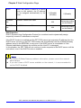
Manual Revisions
Title: PET-7000 DIO User Manual
Manual Number: EMH-013-10
Revision
1.00
Date
May 2009
Effective Pages
All
Description
Original Issue
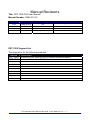
PET-7000 Support List
This manual is for the following modules:
Module
Description
PET-7060 6-channel Power Relay DO and 6-channel Isolated DI Module
PET-7067 8-channel Power Relay DO Module
PET-7000 DIO User Manual, May 2009, V1.00, EMH-013-10----------3
Table of Contents
1.
2.
3.
INTRODUCTION................................................................................................................................................... 7
1.1.
FEATURES ........................................................................................................................................................ 8
1.2.
SPECIFICATIONS ............................................................................................................................................. 11
1.3.
MODULE SELECTION ...................................................................................................................................... 12
1.4.
VIEW OF THE PET-7000 ................................................................................................................................. 18
1.5.
PET-7000 INSTALLATION ............................................................................................................................... 22
1.5.1.
Mounting the PET-7000............................................................................................................................ 22
1.5.2.
Connecting the Hardware......................................................................................................................... 26
1.5.3.
Ethernet cable wiring................................................................................................................................ 27
1.6.
I/O WIRING CONNECTION ................................................................................................................................ 29
1.7.
SOFTWARE & DOCUMENT INFORMATION ....................................................................................................... 30
1.8.
UPDATE INFORMATION ................................................................................................................................... 31
CONFIGURING THE PET-7000 ........................................................................................................................ 32
2.1.
CONFIGURING THE NETWORK SETTINGS ......................................................................................................... 32
2.2.
LOAD FACTORY DEFAULT .............................................................................................................................. 36
WEB CONFIGURATION PAGE........................................................................................................................ 37
3.1.
OVERVIEW ..................................................................................................................................................... 40
3.2.
CONFIGURATION ............................................................................................................................................ 42
3.2.1.
Ethernet Settings ....................................................................................................................................... 42
3.2.2.
Basic Settings............................................................................................................................................ 44
3.2.3.
Module I/O settings................................................................................................................................... 50
3.3.
3.3.1.
Account management................................................................................................................................ 54
3.3.2.
IP filter Settings ........................................................................................................................................ 55
3.4.
4.
AUTHENTICATION .......................................................................................................................................... 54
WEB HMI....................................................................................................................................................... 57
3.4.1.
Web Editing .............................................................................................................................................. 57
3.4.2.
Web HMI................................................................................................................................................... 62
3.5.
I/O PAIR CONNECTION ................................................................................................................................... 75
3.6.
MORE INFORMATION ...................................................................................................................................... 77
HOW TO ACCESS THE PET-7000? .................................................................................................................... 78
4.1.
VIA AN ETHERNET NETWORK ........................................................................................................................ 78
4.2.
USING THE MODBUS PROTOCOL ..................................................................................................................... 79
4.2.1.
Introduction .............................................................................................................................................. 79
4.2.2.
Function Codes Supported........................................................................................................................ 80
4.2.3.
Modbus Register address table ................................................................................................................. 80
PET-7000 DIO User Manual, May 2009, V1.00, EMH-013-10----------4
5.
I/O PAIR CONNECTION.................................................................................................................................... 81
6.
SOFTWARE DEVELOPMENT APPLICATION ............................................................................................. 82
7.
8.
9.
6.1.
LOCATION OF DOCUMENTS AND SOFTWARE ................................................................................................... 82
6.2.
LABVIEW...................................................................................................................................................... 84
OPC SERVER ....................................................................................................................................................... 85
7.1.
INTRODUCTION ............................................................................................................................................... 85
7.2.
PROCEDURE FOR USING THE OPC SERVER ...................................................................................................... 86
7.3.
OPC SERVER EXAMPLE USING MODBUS PROTOCOL .................................................................................... 86
SCADA................................................................................................................................................................... 90
8.1.
INDUSOFT....................................................................................................................................................... 91
8.2.
CITECT ........................................................................................................................................................... 92
8.3.
IFIX ................................................................................................................................................................ 93
TROUBLESHOOTING AND TECHNICAL SUPPORT ................................................................................. 94
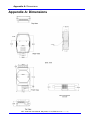
APPENDIX A: DIMENSIONS........................................................................................................................................ 96
APPENDIX B: MINIOS7 UTILITY............................................................................................................................. 98
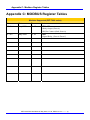
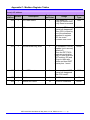
APPENDIX C: MODBUS REGISTER TABLES...................................................................................................... 105
APPENDIX E: JAVA INSTALLATION.................................................................................................................... 149
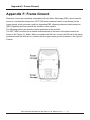
APPENDIX F: FRAME GROUND............................................................................................................................. 154
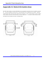
APPENDIX G: NODE INFORMATION AREA....................................................................................................... 155
APPENDIX H: TECHNICAL SUPPORT.................................................................................................................. 156
PET-7000 DIO User Manual, May 2009, V1.00, EMH-013-10----------5
TABLES
Table 1-1 ET-7000 classification ..................................................................................12
Table 1-2 LED Indicators ...............................................................................................19
Table 1-3 J2 Connector .................................................................................................19
Table 1-4 RJ-45 Wiring Standards...............................................................................28
Table 3-1 TCP/IP network settings ..............................................................................42
Table 3-2 Basic Settings................................................................................................48
Table 3-3 Load All Setup Default Table ......................................................................49
Table 3-4 Input or Holding Data Types .......................................................................60
Table 3-5 Main Web HMI Page - Table1 ....................................................................62
Table 3-6 Main Web HMI Page - Table 2 ...................................................................63
Table 3-7 I/O Pair Connection Settings.......................................................................75
Table 4-1 ET-7000 Modbus Function Code ...............................................................80
Table 9-1 Troubleshooting ............................................................................................94
Chapter 1 Introduction
1. Introduction
The PET-7000 features “PoE” technology, not only data but power is carried through an
Ethernet cable. This feature makes installation of the PET-7000 a piece of cake. Imagine
that no more unnecessary wires, only an Ethernet cable takes care of everything in the
field.
The PET-7000 also features a built-in web server and the web HMI function. A built-in web
server allows basic setting configuration, I/O monitoring and I/O control by simply using a
regular web browser. Remote control is as easy as you surf the internet.
As to the web HMI function, no programming or HTML skills are required; creating
dynamic and attractive web pages for I/O monitoring and I/O control would be fun for
engineers ever after.
The PET-7000 also supports Modbus/TCP protocol that makes the PET-7000 be perfect
integrated into SCADA software.
The PET-7000 module is designed for industrial monitoring and measurement
applications, so the hardware could survive in harsh and noisy environment. As a result,
the module contains 2-way isolation against noise and surge signals, has a wild range
power input (10 ~ 30 VDC) and can operating at temperature ranging from -25 ~+75 °C
Package Checklist
The package includes the following items:
z One PET-7000 hardware module
z One Quick Start Manual
z One software utility CD
z One screw driver
Note:
If any of these items are missing or damaged, contact the local distributors for more
information. Save the shipping materials and cartons in case you need to ship the
module/product in the future.
PET-7000 DIO User Manual, May 2009, V1.00, EMH-013-10----------7
Chapter 1 Introduction
1.1.
Features
Built-in web server
Each PET-7000 module has a built-in web server that allows the user to easily
configure, monitor and control the module from a remote location with a regular web
browser.
Web HMI
The Web HMI function allows the user to create dynamic and attractive web pages to
monitor and control the I/O points. The user can upload specific I/O layout pictures
(bmp, jpg, gif format) and define a description for each I/O point. No HTML or Java
skills are needed to create the web pages.
PET-7000 DIO User Manual, May 2009, V1.00, EMH-013-10----------8
Chapter 1 Introduction
I/O Pair Connection
This function is used to create a DI to DO pair through the Ethernet. Once the
configuration is complete, the PET-7000 module can poll the status of remote DI
status with the Modbus/TCP protocol and continuously write to the paired local DO
channels in the background.
Communication Security
An account and a password for the account are needed when logging into the
PET-7000 web server. An IP address filter is also included for limiting authority of
connecting with the PET-7000.
Modbus protocol
z The Modbus/TCP slave function can be used to provide data to remote SCADA
software through the Ethernet port.
Built-in Multi-function I/O
All Digital Output modules provide:
z Power on value (On boot up, the DO status is set to the Power-on value)
z Safe value (If Modbus/TCP communication is lost for a specified period, the DO
status is set to the safe value)
All Digital Input modules provide:
z High/Low latched status
z DI channels can also be used as DI status and 32-bit low speed (500 Hz)
counters.
PET-7000 DIO User Manual, May 2009, V1.00, EMH-013-10----------9
Chapter 1 Introduction
All-in-one module
The various I/O components are mixed with multiple channels in a single module,
which provides the most cost effective I/O usage and enhances performance of the
I/O operations.
2-way isolated noise/surge protection
To protect the hardware from damage caused by noise and surge, the PET-7000
module is designed with isolation circuits for Ethernet, and I/O.
Built-in Dual Watchdog
The Dual Watchdog consists of the/a Module Watchdog and the/a Host Watchdog.
z The Module Watchdog is a built-in hardware circuit that can be used to monitor
the operation of the module and will reset the CPU module if a failure occurs in
either the hardware or the software.
z
The Host Watchdog is a software function that can be used to monitor the
operating status of the host, and is used to prevent network communication
problems or host failures.
Automatic MDI / MDI-X crossover for plug-and-play
The RJ-45 port support automatic MDI/MDI-x that can automatically detect the type of
connection to the Ethernet device without requiring special straight or crossover
cables.
Auxiliary power input
The PET-7000 can receive power from an auxiliary power sources like AC adapters or
battery in addition to the PoE enabled network. This is a desirable feature when the
total system power requirements exceed the PSE's load capacity. Furthermore, with
the auxiliary power option, the PET-7000 can be used in a standard Ethernet (nonPoE) system.
Ventilated housing designed to operate between -25 °C ~ +75 °C
The PET-7000 is housed in a plastic-based shell/case with a column-like ventilator
that helps to cool the working environment inside the shell/case and allows the
PET-7000 to operate at temperatures ranging from -25 °C to +75 °C.
PET-7000 DIO User Manual, May 2009, V1.00, EMH-013-10----------10
Chapter 1 Introduction
1.2.
Specifications
System
z CPU: 80186-80 or compatible
z EEPROM:
16 KB
z SRAM:
512 KB
z FLASH ROM:
512 KB
Communication
z Ethernet Port:
(10/100MBaseT, RJ-45 Port)
Built-in WatchDog Timer (0.8 seconds)
LED indicators
z PoE On
z L1: Run
z L2: Ethernet (Link/Active)
z L3: 10/100M
Isolation
z I/O Isolation:
Dependent on the type of the PET-7000 module.
(Please refer to “Sec 1.3 Module Selection” for more detailed information)
z Ethernet Isolation:
1500 VDC
Power
z IEEE 802.3af, Class 1
z Power requirements: Powered by Power over Ethernet (PoE) or
an auxiliary power input from +12 VDC to +48 VDC
z Power consumption: Dependent on the type of the PET-7000 module.
(Please refer to “Sec 1.3 Module Selection” for more detailed information)
General environment
z Operating temperature: -25 °C ~ +75 °C
z Storage temperature: -30 °C ~ +80 °C
z Relative humidity:
5% ~ 90% RH, non-condensing
Mechanical
z Dimensions (W × L × D): 72 mm x 123 mm x 35 mm
z Installation: DIN-Rail Mounting
I/O Components
z Dependent on the type of of the PET-7000 module, please refer to the next
chapter for more detailed I/O specifications.
PET-7000 DIO User Manual, May 2009, V1.00, EMH-013-10----------11
Chapter 1 Introduction
1.3.
Module Selection
PET-7000 classification
PET-7XYZ
ET: Ethernet communication interface
X: Number of the variance
Y: Function code
Z: Extension function code
Table 1-1 PET-7000 classification
X
Y
Z
1. AI module
3. RTD
4. Transmitter
5. Thermistor
6. Strain Gauge
7. Analog Input
8. Thermocouple
2. AO module
1. Voltage output
2. Current output
Number of variance
3. Reserved
4. DIO module
Number of variance
5. DIO module
Number of variance
6. DIO module with relay
Number of variance
7. Multi-function
1. General purpose
8. Counter / Frequency
Number of variance
9. Motion
N: Number of axes
PET-7000 DIO User Manual, May 2009, V1.00, EMH-013-10----------12
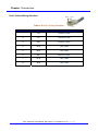
Chapter 1 Introduction
Released Module
Type
Module
Description
PET-7060
6-channel Power Relay Output
6-channel Isolation DI Module
PET-7067
8-Channel Power Relay Output Module
Power Relay Output
PET-7000 DIO User Manual, May 2009, V1.00, EMH-013-10----------13
Chapter 1 Introduction
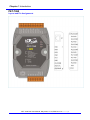
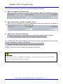
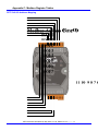
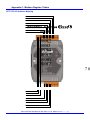
PET-7060
Layout and Pin Assignments
PET-7000 DIO User Manual, May 2009, V1.00, EMH-013-10----------14
Chapter 1 Introduction
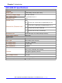
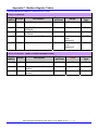
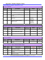
PET-7060 I/O Specifications:
Digital Output
Channels
6
Output Type
Power Relay, Form A (SPST N.O.)
Operating Voltage Range
250 VAC /30 VDC
Max. Load Current
5.0 A/channel at 25 °C
Operating Time
6 ms
Release Time
3 ms
VDE 5 A 250 VAC 30,000 ops (10 ops/minute) at 75°C
5 A 30 VDC 70,000 ops (10 ops/minute) at 75 °C
Electrical Life ( Resistive load )
UL
5 A 250 VAC/30 VDC 6,000 ops.
3 A 250 VAC/30 VDC 100,000 ops.
Mechanical Life
20,000,000 ops. at no load (300 ops./minute).
Relay Output Isolation
Digital Input
3000 Vrms
Channels
6
Input Type
Wet Contact (Sink, Source)
On Voltage Level
+10 VDC ~ +50 VDC
Off Voltage Level
+4 VDC max.
Input Impedance
10 kOhm
Intra-module Isolation
3750 Vrms
Max. Count: 4,294,967,285 (32 bits)
Counters
Max. Input Frequency: 500 Hz
Min. Pulse Width: 1 ms
Over-Voltage Protect
Power
+70 VDC
Power consumption
0.12 A @ 24 VDC max.
PET-7000 DIO User Manual, May 2009, V1.00, EMH-013-10----------15
Chapter 1 Introduction
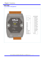
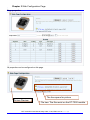
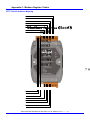
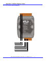
PET-7067
Layout and Pin Assignments
PET-7000 DIO User Manual, May 2009, V1.00, EMH-013-10----------16
Chapter 1 Introduction
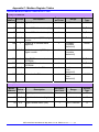
PET-7067 I/O Specifications:
Digital Output
Channels
8
Output Type
Power Relay, Form A (SPST N.O.)
Operating Voltage Range
250 VAC / 30 VDC
Max. Load Current
5.0 A/channel at 25 °C
Operating Time
6 ms
Release Time
3 ms
VDE 5A 250 VAC 30,000 ops (10 ops/minute) at 75 °C
5A 30 VDC 70,000 ops (10 ops/minute) at 75 °C
Electrical Life ( Resistive load )
UL
5A 250 VAC/30 VDC 6,000 ops.
3A 250 VAC/30 VDC 100,000 ops.
Mechanical Life
20,000,000 ops. at no load (300 ops./minute).
Relay Output Isolation
Power
3000 Vrms
Power consumption
0.14 A @ 24 VDC max.
PET-7000 DIO User Manual, May 2009, V1.00, EMH-013-10----------17
Chapter 1 Introduction
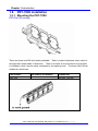
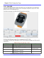
1.4.
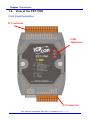
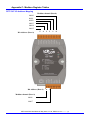
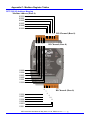
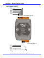
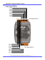
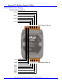
View of the PET-7000
Front Panel Description
J1 Connector
LED
Indicators
J2 Connector
PET-7000 DIO User Manual, May 2009, V1.00, EMH-013-10----------18
Chapter 1 Introduction
Table 1-2 LED Indicators
LED Action
Function
Name
Run
Flashing
Firmware is running
LINK/ACT
ON
OFF
Flashing Green
OFF
Orange
Ethernet link detected
No Ethernet link detected
Ethernet packet received
Speed 10 Mbps
Speed 100 Mbps
10/100M
Note:
If the Run LED does not display the information as above, the following steps
should be taken:
z Power-off the module
z
z
Check that the Init/Normal switch is in the Normal position.
(Refer to Back Panel Description)
Re-power-on the module and double check the LED indicators.
J1 Connector
Refer to Sec.1.3 Module Selection for more details regarding the pin assignment of the
J1 Connector for all types of PET-7000 series modules.
J2 Connector
Pin number
Name
Table 1-3 J2 Connector
Function
8
+VS
The PET-7000 series can be powered using an
auxiliary power +12 VDC ~ +48 VDC
(non-regulated)
9
GND
Ground connection
The definition of pin8 and pin9 applies to all types of the PET-7000 series modules. The
definition of the other pins is dependent on the type of the PET-7000 series module.
PET-7000 DIO User Manual, May 2009, V1.00, EMH-013-10----------19
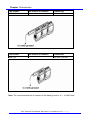
Chapter 1 Introduction
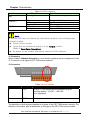
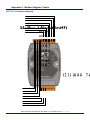
Back Panel Description
Init/Normal switch
Init mode: MiniOS7 configuration mode
Normal mode: Firmware running mode
During the PET-7000 working time, the Switch is ALWAYS in the Normal position. Only
when updating the PET-7000 firmware or OS, the switch can be moved from the Normal
position to the Init position.
Move the Switch to the Normal position after the update is complete.
PET-7000 DIO User Manual, May 2009, V1.00, EMH-013-10----------20
Chapter 1 Introduction
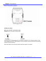
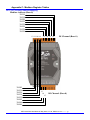
Bottom Panel Description
RJ45 Port
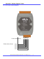
Frame Ground
Note:
Appendix F describes how to connect the Frame Ground to the PET-7000 series
PET-7000 DIO User Manual, May 2009, V1.00, EMH-013-10----------21
Chapter 1 Introduction
1.5.
PET-7000 installation
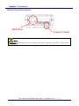
1.5.1. Mounting the PET-7000
DIN Rail Mounting
There are three new DIN rail models available. Each is made of stainless steel, which is
stronger than those made of aluminum. There is a screw at one end and a ring terminal
is included so that it can be easily connected to the earth ground. The three new DIN rail
models are as follows.
Part number
Max number of modules
Dimensions
DRS-360
5
360 mm x 35 mm
PET-7000 DIO User Manual, May 2009, V1.00, EMH-013-10----------22
Chapter 1 Introduction
Part number
Max number of modules
Dimensions
DRS-240
3
240 mm x 35 mm
Part number
Max number of modules
Dimensions
DRS-125
2
125 mm x 35 mm
Note: The recommended wire to connect to the earth ground is 16 – 14 AWG wire.
PET-7000 DIO User Manual, May 2009, V1.00, EMH-013-10----------23
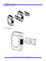
Chapter 1 Introduction
Piggyback Mounting
Wall Mounting
PET-7000 DIO User Manual, May 2009, V1.00, EMH-013-10----------24
Chapter 1 Introduction
Snap the PET-7000 onto the DIN-rail (refer to the Snap On picture below)
Snap the PET-7000 off from the DIN-rail (refer to the Snap Off picture below)
PET-7000 DIO User Manual, May 2009, V1.00, EMH-013-10----------25
Chapter 1 Introduction
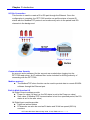
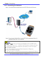
1.5.2. Connecting the Hardware
Step 1: Connect the Ethernet cable between the PET-7000 and the PoE switch.
Pin31
Pin30
Step 2: Check that the “RUN” LED (L1) on the PET-7000 is periodically ON for 0.5
seconds and then OFF for 0.5 seconds.
Notes:
z Pin 8 and Pin 9 on the J2 connector are designed as VS+ and GND for the
auxiliary power input (+12 ~ +48 VDC) if the PoE switch is lacked or the total
system power requirements exceed the load capacity of user’s PoE switch.
z NE-205PSE web page:
http://www.icpdas.com/products/Switch/industrial/ns-205pse.htm
z Power of NS-205PSE web page:
http://www.icpdas.com/products/Accessories/power_supply/mdr-60-48.htm
PET-7000 DIO User Manual, May 2009, V1.00, EMH-013-10----------26
Chapter 1 Introduction
1.5.3. Ethernet cable wiring
Connecting the PET-7000 to Switch or Hub
Connecting the PET-7000 to a Host PC
As a result of the automatic MDI / MDI-X crossover for plug-and-play on the PET-7000
RJ45 port, there is no need to a crossover cable to connect the PET-7000 to the Host PC.
The user just uses a general straight-through cable to make the connection.
The straight-through cable is shown as follows:
PET-7000 DIO User Manual, May 2009, V1.00, EMH-013-10----------27
Chapter 1 Introduction
RJ-45 Cables Wiring Standard
Pin-8
Pin-1
Table 1-4 RJ-45 Wiring Standards
Pin Number
Signal
Function
1
Tx+
Transmit Data +
2
Tx-
Transmit Data -
3
Rx+
Receive Data +
4
N/A
Not Used
5
N/A
Not Used
6
Rx-
Receive Data -
7
N/A
Not Used
8
N/A
Not Used
PET-7000 DIO User Manual, May 2009, V1.00, EMH-013-10----------28
Chapter 1 Introduction
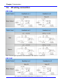
1.6.
I/O wiring connection
PET-7060
Note: Source type is provided with hardware PCB version 1.3 and later
PET-7067
PET-7000 DIO User Manual, May 2009, V1.00, EMH-013-10----------29
Chapter 1 Introduction
1.7.
Software & Document information
The location of all documents and software related to the PET-7000 module is shown in
the following directory structure diagram. The relevant file can quickly be located by
referring to the diagram.
For details of the revision information, please refer to
CD:\NAPDOS\PET7000\Firmware\Version_nnn_Eng.txt or Version_nnn_Chi.txt
PET-7000 DIO User Manual, May 2009, V1.00, EMH-013-10----------30
Chapter 1 Introduction
1.8.
Update Information
Refer to http://www.icpdas.com/products/Remote_IO/et-7000/pet7k_manual_software.htm
PET-7000 DIO User Manual, May 2009, V1.00, EMH-013-10----------31
Chapter 2 Configuring the ET-7000
2. Configuring the PET-7000
The following settings need be set correct before the PET-7000 working. Network settings
need meet the Network demand of Host PC; username and password settings are for the
security issue.
z
z
2.1.
Network settings:
Item
IP Address
Subnet Mask
Gateway
Default
192.168.255.1
255.255.0.0
192.168.0.1
Web page Configuration
Item
Default
Username
Admin (Case sensitive)
Password
Admin (Case sensitive)
Configuring the network settings
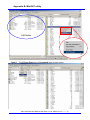
MiniOS7 utility is used to set the Ethernet address settings via the Ethernet. It can also
download files to the PET-7000 module and update the OS image.
Follows are the steps of configuring the network settings.
Step 1:
z
Refer to Sec. 1.5.2 for details regarding wiring connections for PET-7000 series
modules.
Note:
The Init/Normal switch is always placed in the Normal position.
Step 2: Install MiniOS7 Utility on the host PC by executing
CD:\NAPDOS\ET7000\Tools\Tools for MiniOS7\MiniOS7_utility\MiniOS7_Utility.exe and
follow the on-screen instructions
PET-7000 DIO User Manual, May 2009, V1.00, EMH-013-10----------32
Chapter 2 Configuring the ET-7000
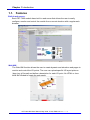
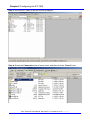
Step 3: Run MinioS7 utility as per the following diagram.
Step 4: Select the Connection item of main menu, and then click the “Search” item.
PET-7000 DIO User Manual, May 2009, V1.00, EMH-013-10----------33
Chapter 2 Configuring the ET-7000
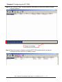
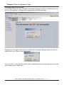
Step 5: The “MiniOS7 Scan” window appears, and starts to search the modules on this
Ethernet network.
Progress is running
Step 6: When the search is finished, click the PET-7000 module which you want to
configure and then click the “IP setting” button.
PET-7000 DIO User Manual, May 2009, V1.00, EMH-013-10----------34
Chapter 2 Configuring the ET-7000
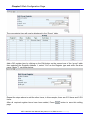
Step 6: IP Setting window appears.
Step 6.1: Check that valid IP, Mask, Gateway. Alias, DHCP values have been inserted
into the “Recommend Settings” fields.
Step 6.2: If these values are modified, click the “Set” button to set the new values.
Step 7: When “Set” button is clicked, the PET-7000 will restart to make the new settings
take effect. Search the module again to make sure the new settings are valid.
Note:
Please refer to Appendix B for more details regarding the MiniOS7 Utility installation
procedure.
PET-7000 DIO User Manual, May 2009, V1.00, EMH-013-10----------35
Chapter 3 Web Configuration Page
2.2.
Load Factory Default
Refer to “Load All Setup Default” in Sec 3.2.2 Basic Setting for more details regarding
loading the factory default using the Web configuration.
PET-7000 DIO User Manual, May 2009, V1.00, EMH-013-10----------36
Chapter 3 Web Configuration Page
3. Web Configuration Page
The PET-7000 series modules have a built-in Web configuration page with a friendly user
interface; it is simple to configure the PET-7000 with using a regular web browser.
The web configuration page is optimized for Microsoft Internet Explorer 6.0 and Mozilla Firefox,
and the other browsers can work well, but the Web might appear differently.
No extra tools or utilities are needed to configure and control the PET-7000.
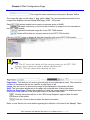
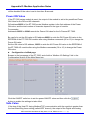
Opening the browser to connect with the PET-7000
1 Start up the Internet Explorer or Mozilla Firefox, and click the URL block at the top of the
screen.
2 Input the URL address of the PET-7000 (Such as http://192.168.255.1) into the URL block
and press the “Enter” button to enter the login page.
z
z
z
3
Note:
The Factory default IP address is 192.168.255.1
The default user name and password are Admin and Admin (Case sensitive)
If you forget the user name or password, the ONLY way to start configuring the
PET-7000 is to load factory default by using the web/console configuration
Input the User Name and password on the dialog, and then click the “OK” button. (See the
dialog box below)
PET-7000 DIO User Manual, May 2009, V1.00, EMH-013-10----------37
Chapter 3 Web Configuration Page
After the user name and password are accepted, the PET-7000 home page will be displayed.
Note:
If either the user name or the password is incorrect or is left blank, the main home
page and all other pages will not be accessible, so ensure that the input data is correct
and rectify it if and as necessary.
PET-7000 DIO User Manual, May 2009, V1.00, EMH-013-10----------38
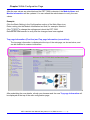
Chapter 3 Web Configuration Page
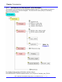
The brief description of the Web page configuration function is listed on six main functions of
the tree structure.
Overview: A
brief introduction to the six functions
Configuration: Network Settings, Serial Port, Basic and
Module I/O Settings
Authentication: Account Management and Accessible IP
Settings
Web HMI: Web Human-Machine Interface and Web Editing
Pair Connection: Create the I/O mapping for two identical
PET-7000 series modules.
More Information: Detailed specifications and More
information about the PET-7000 series
PET-7000 DIO User Manual, May 2009, V1.00, EMH-013-10----------39
Chapter 3 Web Configuration Page
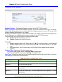
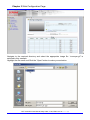
3.1.
Overview
The Welcome page for the PET-7000 contains information related to the currently accessed
PET-7000 series module, as shown below:
Model Name: PET-7000 series module name (The default is the PET-7000 series name. The
maximum length is 8 characters)
MAC address: The MAC address of the PET-7000 series module
Module Information: The alias name of the PET-7000 series module
Firmware Version: The version number and date of the default firmware
OS Version: The version number and date of the operating system
DI/DO/AI/AO channel: The number of DI/DO/AI/AO channels on the PET-7000 module.
PET-7000 DIO User Manual, May 2009, V1.00, EMH-013-10----------40
Chapter 3 Web Configuration Page
PET-7000 DIO User Manual, May 2009, V1.00, EMH-013-10----------41
Chapter 3 Web Configuration Page
3.2.
Configuration
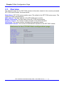
3.2.1. Ethernet Settings
The Ethernet settings page can be used to check and change the TCP/IP network settings of
the PET-7000 module.
Settings
IP
Gateway
Mask
Table 3-1 TCP/IP network settings
Description
Range
4-byte IP address. Each PET-7000
X.X.X.1
module needs an IP address so that if
To
can be identified on the network
X.X.X.254
4-byte Gateway. A
gateway is a
network address that acts as an
entrance to another network. Usually,
computers that control the traffic within
the network or at the local Internet
Service Provider (ISP) are gateway
nodes.
4-byte subnet Mask. A subnet mask
represents all the network hosts at one
geographic location on the same local
area network. When an Ethernet packet
is sent across the network, the ET-7000
will use the subnet Mask to check
whether the TCP/IP host specified in the
packet is on local network segment.
Factory default
192.168.255.1
X.X.X.0
To
X.X.X.254
192.168.0.1
X.X.X.0
To
X.X.X.255
255.255.0.0
PET-7000 DIO User Manual, May 2009, V1.00, EMH-013-10----------42
Chapter 3 Web Configuration Page
DHCP
Select this option If there is a DHCP
server on the network, the IP address
can be assigned automatically by the
server.
Firmware
Ver.
Firmware Version and Date
MiniOS7
Ver.
MiniOS7 Version and Date
0 (Disable)
1(Enable)
0 (Disable)
N/A
Varies depending
on the Module
N/A
Varies depending
on the Module
DHCP function
DHCP (Dynamic Host Configuration Protocol) is a method used to dynamically assign
temporary numeric IP addresses as required.
If the DHCP function is enabled and the PET-7000 cannot get a dynamic IP address from the
DHCP server on boot up, the PET-7000 module will automatically load the IP/Mask/Gateway
address saved in the EEPROM. It may occur if the DHCP server is unavailable or if the
Ethernet cable/device between the module and the Host PC is damaged.
In this situation, the PET-7000 will not continue to make requests to the DHCP server until the
next reboot, even if the DHCP function is enabled.
z
z
Notes:
For correct IP/Mask/Gateway address information, please consult the network
administrator.
If you don’t have a DHCP server available on the network, it is recommended to
set the DHCP disabled.
PET-7000 DIO User Manual, May 2009, V1.00, EMH-013-10----------43
Chapter 3 Web Configuration Page
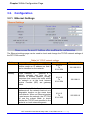
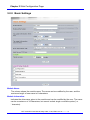
3.2.2. Basic Settings
Module Name:
The column shows the module name. The name can be modified by the user, and the
maximum length of new name is 8 characters.
Module Information:
Indicates the alias name given to the module and can be modified by the user. The name
can be a maximum of 16 characters, but cannot include single or double quotes (' or
“ character).
PET-7000 DIO User Manual, May 2009, V1.00, EMH-013-10----------44
Chapter 3 Web Configuration Page
After the new values are submitted and the PET-7000 is rebooted, the Module Name and
Module Information will be updated. You can refresh the web browser to verify the new
values.
Example:
Click the Basic Setting in the Configuration section of the Main Menu tree.
Enter a string into the Module Information text field, for example, Module1.
Click
to change the settings and reboot the PET-7000.
Refresh the web browser to verify that the changes have been applied.
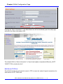
Top page Information (First line) and Top page Information (second line):
The top page information is displayed at the top of the web page, as shown below, and
can be modified to custom information.
After submitting the new details, refresh your browser and the new Top page Information will
be displayed at the top of the web configuration page.
PET-7000 DIO User Manual, May 2009, V1.00, EMH-013-10----------45
Chapter 3 Web Configuration Page
Example:
Click “Basic Settings” in the Configuration Section of the Main Menu tree.
Enter a string in the Top page Information (First line) and Top page Information (second line)
text fields, for example “ICPDAS” and “http://www.icpdas.com”. The font size and color can be
modified by selecting an option from the color drop down box and entering a value in the font
text field.
Click
button to enable the new settings.
Refresh your browser.
More Information URL:
It is helpful to provide users with additional information while browsing the Web
Configuration page.
After submitting the new details, the More Information link in the Main menu tree will be
updated.
Example:
Click the “Basic Settings” if the Configuration Section of the Main Menu tree
Enter a URL in the “More Information URL” text field, for example “http://www.w3.org”. (The
URL may be either an external site or a link to a page on your intranet)
Click
to enable the settings to take effect.
PET-7000 DIO User Manual, May 2009, V1.00, EMH-013-10----------46
Chapter 3 Web Configuration Page
Clicking the “More Information” in the Main Menu tree will automatically open the web page
defined in the More Information URL.
The default URL for “More information” is “http://www.icpdas.com/products/Remote_IO/ET7000/ET-7000_introduction.htm”
Web Server TCP Port:
The default well known port which is used in TCP to name the ends of logical connections for
Web server of PET-7000 is 80.
PET-7000 DIO User Manual, May 2009, V1.00, EMH-013-10----------47
Chapter 3 Web Configuration Page
It allows the user to change the port to other port. (0~65535)
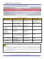
Table 3-2 Basic Settings
Function Name
Description
Range
Factory default
Module Name
The name of the PET7000 series module
Maximum of 8
characters
Depends on the
type of the
PET-7000 Module
Module Information
Alias or nickname
assigned to the Module
Maximum of 16
characters
None
Top page
Information
(First line)
User-defined
Information
Maximum of 20
characters
None
Top page
Information
(Second line)
User-defined
Information
Maximum of 50
characters
None
More Information
URL
The URL can be linked
to a user specified Web
page.
Maximum of 100
characters
None
Web Configuration
Web configuration via a
Web browser
Enable/Disable
Enable
Telnet console
Console mode via an
Ethernet (Telnet).
Enable/Disable
Enable
z
Notes:
The contents of “Top page Information (First line)”, “Top page Information (Second
line)” and “More Information URL” will not return to default when running “loading
the factory default”. Users can only change the contents from the “Basic Settings”
page of the PET-7000
PET-7000 DIO User Manual, May 2009, V1.00, EMH-013-10----------48
Chapter 3 Web Configuration Page
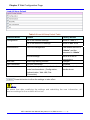
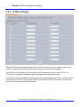
Load All Setup Default
Table 3-3 Load All Setup Default Table
Function Name
Details
Factory default
Configuration
All of the Ethernet settings
Refer to Table 3-1
All of the Module I/O settings
Refer to Sec. 3.2.3
Account management
The default account is
“Admin” and the
password is “Admin”
IP filter settings
Allow all of the IP
connections
Web HMI
Web Page editing function
0 pages
Pair Connection
I/O Pair connection
Disabled
All
Set the factory default value for the 4
main functions above. (Configuration,
Authentication, Web HMI, Pair
Connection)
Refer to the function
details above.
Authentication
: Press this button to allow the settings to take effect.
Note:
Be aware that after modifying the settings and submitting the new information, all
previous settings for the module will be lost.
PET-7000 DIO User Manual, May 2009, V1.00, EMH-013-10----------49
Chapter 3 Web Configuration Page
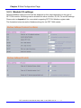
3.2.3. Module I/O settings
Different Modbus setting functions will be displayed on this page depending on the type of
PET-7000 module. All settings can be divided into either common, DI, DO, AI and AO settings.
Please refer to Appendix C for more details regarding PET-7000 Modbus register table.
The illustration below shows the Modbus settings for the PET-7060 module
PET-7000 DIO User Manual, May 2009, V1.00, EMH-013-10----------50
Chapter 3 Web Configuration Page
PET-7000 DIO User Manual, May 2009, V1.00, EMH-013-10----------51
Chapter 3 Web Configuration Page
PET-7000 DIO User Manual, May 2009, V1.00, EMH-013-10----------52
Chapter 3 Web Configuration Page
Modbus Registers and Factory Defaults
Common Functions
Modbus
Address
Points
Description
40257
1
Set host watch dog timer 5~65535 (Enable)
(Second)
(<5: Disable)
Range
Factory
default
0 (Disable)
DI Module Functions
Modbus
Address
Points
(Max.)
00150
Factory
default
Description
Range
1
Enable all DI latched
status (high/low)
0 (Disable)
1(Enable)
0 (Disable)
00151~
00166
16
Enable low speed
(100Hz) digital counter
0 (Disable)
1(Enable)
0 (Disable)
40050~
40081
16
Preset value for low
speed (100Hz) digital
counter
0~4294967296
0
Factory
default
DO Module Functions
Modbus
Address
Points
(Max.)
Description
Range
00235~
00266
32
Power on value for DO
0=off
1=on
0
00267~
00298
32
Safe value for DO
0=off
1=on
0
PET-7000 DIO User Manual, May 2009, V1.00, EMH-013-10----------53
Chapter 3 Web Configuration Page
3.3.
Authentication
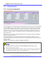
3.3.1. Account management
Each PET-7000 series module provides access privilege for up to five user accounts including
a default Admin account and four general user-defined accounts. Each of the user-defined
accounts can be assigned either Admin or general user privilege. Assigning Admin privilege
allows the account to read and write configuration settings but the general user account is
restricted to read only access. The maximum number of characters that can be used for an
account name is 8.
Each of the account requires password authentication. The maximum number of characters
allowed for the password is 8.
Load Setup Defaults: Load the factory default Account management settings. All current
accounts will be deleted, except the Admin account, and the password of Admin account will
revert to “Admin”.
: Press this button to enable the settings to take effect.
z
z
Notes:
The default account is “Admin” and the password is also “Admin”. The
password and the Admin account can be changed, but the account name
cannot be changed or deleted.
If you forget the password for the Admin account, the ONLY way to configure the
ET-7000 is by using the “Reset to Factory default” option. (Please refer to Load
All Setup Default on Sec. 3.2.3 for more information)
PET-7000 DIO User Manual, May 2009, V1.00, EMH-013-10----------54
,
Chapter 3 Web Configuration Page
3.3.2. IP filter Settings
Each PET-7000 series module contains an IP filter that can be used to control access to the
module, thereby preventing unauthorized access from unknown IP addresses.
The IP filter can be granted across a range of IPv4 addresses, such as from 10.0.8.1 to
10.0.9.22 or to a single IP address, with a maximum of ten permission rules.
Once the IP addresses that have been granted access permission have been entered, and the
rule activated, the PET-7000 module IP filter will guard the TCP/IP connection by restricting
access to any unauthorized IP addresses.
PET-7000 DIO User Manual, May 2009, V1.00, EMH-013-10----------55
,
Chapter 3 Web Configuration Page
There are three methods of restricting or granting access permissions.
z
Allow one specific IP address only
Enter the same IP address in both the “From IP address” and “TO IP address” text fields
z
Allow Hosts within a specific IP address range
Enter the first IP address in the From IP address text field, and enter the last IP address in
the permitted range in the To IP address text field.
z
Allow access from any IP address
Disable IP filter function to allow access to the ET-7000 module from any address.
The “Enable the IP filter table” checkbox must be checked when granting permissions to either
a single IP address or a range of IP address.
: Press this button to enable the settings to take effect.
Note:
The IP filter is set to “disabled” as default; it means that access to the PET-7000
module is allowed from any IP address.
PET-7000 DIO User Manual, May 2009, V1.00, EMH-013-10----------56
Chapter 3 Web Configuration Page
,
3.4.
Web HMI
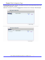
3.4.1. Web Editing
The Web page configuration can be used to create a user-defined Web page.
Click “Web Editing” in the “Web HMI” section of the Main menu tree and the window above will
be displayed.
Click the “Add new Page” button to create a new page.
Click the “Edit” link to edit the selected page.
Click the “Delete” link to remove the selected page.
The list box on the left hand side of the “Web Page Configuration” window lists all existing
pages including the main page, pair connection page.
A maximum of 10 pages can be created.
: Browses the Web HMI with the name listed on the list box.
z
z
z
Notes:
By default, no existing pages will be listed in the Web Page Configuration window.
The “Main page” shown in the HMI list box located on the left hand side of the
“Web Page Configuration” window is a standard default Web HMI page and
cannot be deleted.
The Pair Connection Page can be enabled by enabling the I/O pair connection
function in the “Pair connection” section of the Main menu tree. Please refer to
Sec 3.5 for more details.
PET-7000 DIO User Manual, May 2009, V1.00, EMH-013-10----------57
,
Chapter 3 Web Configuration Page
Page properties
All properties can be configured on this page.
The free space for picture
Picture Preview
File tree: The files exist on the ET-7000 module
PET-7000 DIO User Manual, May 2009, V1.00, EMH-013-10----------58
,
Chapter 3 Web Configuration Page
A maximum of 10 items in each group can be configured.
: The image file name selected by clicking the “Browse” button.
The image file type can be either of .jpg, .gif or .bmp. The recommended resolution for the
image to be displayed on the Editing Web page is 340 * 250 pixels.
Each PET-7000 series module has a maximum storage space of 64KB.
: Browse a directory on the local disk to select an image file to be uploaded to
the PET-7000 module.
: Upload the selected image file to the PET-7000 module.
: Delete all files that are currently stored on the PET-7000 module.
Click the
button to delete all files that currently exist on the PET-7000 module.
Notes:
z The “Del All” action will delete all files currently stored on the PET-7000
module, and it cannot be used to delete individual files.
z The PET-7000 will reboot after deleting the files.
Page Name: This field can be used to give the page a more descriptive name. The maximum
number of characters that can be used for a page name is 10.
Image: Use the list box to choose the image to be displayed in the preview window.
Save: The information displayed on this page will be saved after clicking this button.
Set as the Start Page: Clicking the checkbox to make the current page to be displayed when
clicking the Web HMI link in the Web HMI section of the Main Menu tree.
: Clicking this button will link to the “Edit Group Register” page to allow the point
information to be edited.
: Click the “Clear” button to delete the point information.
Refer to next Section for more details regarding the definition of the field if the “Group” Table.
PET-7000 DIO User Manual, May 2009, V1.00, EMH-013-10----------59
,
Chapter 3 Web Configuration Page
Editing the Group Register
Modbus Register: The Modbus Register number for the PET-7000 module
Alias: A string that describes the Modbus register. It can be a reference to a tag in the image
of the Web editing page which is selected from the “Page properties” section. (If the tag of the
Modbus register has defined on the image)
Scaling: The Modbus register value will be divided by the scale value before being displayed
on the web page, or multiplied before value is written to the PET-7000 module.
This function is only used for Input or Holding register types.
Enable: Enable the Scaling function
Disable: Disable the Scaling function.
Example:
1. Modbus register value= 620, Scale value=10 Î 62.0 will be shown on the Web page.
2. Modbus register value=7325, Scale value=1000 Î 7.325 will be shown on the Web
page.
3. Web page input= 32.20, Scale value=100 Î 3220 will be written to the Modbus
register.
Register Type: Defines the Modbus register type.
Bit format: Coil (Digital Output), Discrete input (Digital Input).
Byte format: Input (Analog Input), Holding (Analog Output).
Data Type: Defines the data type of the Modbus register and must be either Input or Holding.
The data type can be one of the following:
Data Type
Unsigned 16
Table 3-4 Input or Holding Data Types
Definition
A 16-bit positive value
Signed 16
A16-bit value with a sign
Unsigned 32
A 32-bit positive value. The Most significant word (register) is on the
low address.
Signed 32
A 32-bit value with sign. The Most significant word (register) is on the
low address.
PET-7000 DIO User Manual, May 2009, V1.00, EMH-013-10----------60
,
Chapter 3 Web Configuration Page
Unsigned 32
(swapped)
A 32-bit positive value. The Most significant word (register) is on the
high address.
Signed 32 (Swapped) A 32-bit value with sign. The Most significant word (register) is on the
high address.
Float
A 32-bit floating point. (IEEE754).The Most significant word (register)
is on low address.
Float (swapped)
•
A 32-bit floating point. (IEEE754). The Most significant word (register)
is on high address.
: Click this button to save all settings.
The diagram below shows an example of how to select a Coil register type with a Modbus
Register Address of 1 and Alias name of Voltage 1.
Other text fields that aren’t related to the Coil register type will be disabled.
The Modbus Register and Alias text fields are only related to the Coil and Discrete Input
register types, but the other fields aren’t related.
PET-7000 DIO User Manual, May 2009, V1.00, EMH-013-10----------61
Chapter 3 Web Configuration Page
3.4.2. Web HMI
The first page displayed when clicking “Web HMI” item in the Main Menu tree is defined by
checking “Set as Start Page” checkbox on the “Web page configuration” page in the “Web
Editing” section of the Main Menu tree.
The default start page is the Main Web HMI page shown as follow.
The Main Web HMI page shows all the components of the PET-7000.
For example, the Main Web HMI page for a PET-7060 module will display the 6 DO and 6 DI
components.
Title Name
No.
Register
Action
Counter & Clear
High Latch
Low Latch
Table 3-5 Main Web HMI Page - Table1
Description
The Component type and address
The Register address
DI: ON (1), OFF (0)
DI Low Speed Counter, 0~65535
Notes
Press the button to
clear the counter
DI High Latch Status:
Unlatched (0), latched(1)
DI Low Latch Status:
Unlatched (0), latched(1)
PET-7000 DIO User Manual, May 2009, V1.00, EMH-013-10----------62
Chapter 3 Web Configuration Page
Title Name
No.
Register
Action
Table 3-6 Main Web HMI Page - Table 2
Description
The Component type and address
The Register address
DO: ON (1), OFF (0)
AO: A numeral of Integer or float
Notes
Connection Status:
The status indicates the connection status of the IO component on PET-7000 module defined
on the cell of IO channel and Modbus register mapping table.
: When the “Normal” status is highlighted on the each cell, it indicates
that the connection is active, meaning that a connection has been established between the
browser and the IO component on the ET-7000 module and that the component can be
accessed.
When the “Abnormal” status is highlighted on the each cell, It
indicates that the connection has been lost or a communication timeout has occurred.
Indicates that the defined channel is invalid, and is only
applicable to the “Web Editing” or “Pair connection” pages.
PET-7000 DIO User Manual, May 2009, V1.00, EMH-013-10----------63
Chapter 3 Web Configuration Page
The color of the cells in the table shown on the Web page below have turned red, indicating
that the connection to the module has failed.
PET-7000 DIO User Manual, May 2009, V1.00, EMH-013-10----------64
Chapter 3 Web Configuration Page
Java Web page cannot be RUN
If your Web browser isn’t JAVA enabled, a message notifying you that your Web browser can
NOT run Java applets” message will be displayed on the Web HMI page.
Depending on the type of Web browser, a dialog box will appear asking whether you wish to
install Java or not. (Refer to the figure below)
If you click “OK”, a new browser window will be opened linking to the http://www.java.com web
site to enable you to install Java.
PET-7000 DIO User Manual, May 2009, V1.00, EMH-013-10----------65
Chapter 3 Web Configuration Page
To test whether Java is installed or not, visit http://java.com/en/download/installed.jsp.
Please refer to Appendix E for more details regarding JAVA installation.
PET-7000 DIO User Manual, May 2009, V1.00, EMH-013-10----------66
Chapter 3 Web Configuration Page
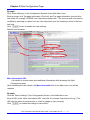
An example of how to create a Web Editing Page
Create a Web page to monitor the I/O of the conveyer system shown below. The I/O system
contains 3 photo sensors that are used to detect the products, and 3 switches that are used to
turn the conveyer motor on and off.
Click the “Web Editing” link in the “Web HMI” section of the Main Menu tree and the “Web
page Configuration” window will be displayed on the right hand of the browser windows.
Click the “Add new Page” button to create a new editing page.
First, you can upload an image file for your new web page.
Click the “Browse” button to locate the file (.jpg, .gif, .bmp) on your system.
PET-7000 DIO User Manual, May 2009, V1.00, EMH-013-10----------67
Chapter 3 Web Configuration Page
Navigate to the required directory and select the appropriate image file. “conveyer.gif” is
selected in this example.
Highlight the file name and Click the “Open” button to make your selection.
PET-7000 DIO User Manual, May 2009, V1.00, EMH-013-10----------68
Chapter 3 Web Configuration Page
Click “Upload” button to upload the selected file to the PET-7000 module.
After the upload is completed, the “conveyer.gif” file should now be listed in the file tree and
also in the image list box.
1. Enter the page name “Conveyer” to the “Page Name” text field.
2. Select the “conveyer.gif“ file from the image list box (the image will be shown in the Preview
window)
PET-7000 DIO User Manual, May 2009, V1.00, EMH-013-10----------69
Chapter 3 Web Configuration Page
To add a register item, click the
button in the first row of the “Group” table and the “Edit
Group Register” window will be displayed.
Add a new DI item using the Register Address 1, then select Discrete Input as the register
type and enter “PHS1” as the alias. Refer to the following two diagrams as an example, then
Press
button to save the information on this page.
PET-7000 DIO User Manual, May 2009, V1.00, EMH-013-10----------70
Chapter 3 Web Configuration Page
The new register item will now be displayed in the “Group” table.
Add a DO register item by clicking on the Edit button on the second row of the “group” table
then selecting the Register Address 1, select “Coil” as the Register type and enter the alias
name “Motor 1”, as shown below..
Repeat the steps above to add the other items, in this example, there are 3 DI items and 3 DO
items.
After all required register items have been added, Press
button to save this editing
page.
PET-7000 DIO User Manual, May 2009, V1.00, EMH-013-10----------71
Chapter 3 Web Configuration Page
PET-7000 DIO User Manual, May 2009, V1.00, EMH-013-10----------72
Chapter 3 Web Configuration Page
An editing page named as “Conveyer” has added to the list box on the top left-hand side of the
“Web Page Configuration” window.
Select the “Conveyer” item and click
button to browse to the “Conveyer” Web HMI page.
PET-7000 DIO User Manual, May 2009, V1.00, EMH-013-10----------73
Chapter 3 Web Configuration Page
The “conveyer.gif” image file and all register items will be displayed on the “Conveyer” Web
HMI page.
Note:
It is recommended that you check whether the browser is JAVA enabled before browsing the
Web HMI. If Java is not installed, please refer to Appendix E for details of how to install
JAVA.
PET-7000 DIO User Manual, May 2009, V1.00, EMH-013-10----------74
3.5.
Chapter 3 Web Configuration Page
I/O Pair Connection
The function makes a DI to DO pair through the Ethernet based on Modbus/TCP. Once the
configuration is done, the PET-7000 can poll Remote DI status and then write to the paired
local DO constantly in the background.
Settings
I/O Pair
connection
Remote IP
Remote TCP port
Remote Net ID
Connection
timeout
Reconnect
interval
Table 3-7 I/O Pair Connection Settings
Description
Range
Enable/Disable I/O pair connection
Enable, Disable
IP address of remote device
port number of remote device
Modbus Net ID of remote device
Timeout to build a connection.
Continue to attempt to reconnect to the
remote module once the connection is
lost until the reconnection time has
expired.
Time period to establish the
Scan time
communication
Communication Timeout for Modbus/TCP
communication.
timeout
Remote DI base DI base address of Remote DI device
that will be mapped to local DO register.
address
Remote DO base DO base address of local DO register
that will be mapped to remote DI device.
address
I/O count mapped from the base
I/O count
address
Default
Disable
0
0~65535
502
0~255
1
0~ 42949672965 ms 5000 ms
0~ 42949672965 ms 10000 ms
0~ 42949672965 ms 1000 ms
0~ 42949672965 ms 500 ms
Depend on the ET- 0
7000
Depend on remote 0
device
1~255
0
PET-7000 DIO User Manual, May 2009, V1.00, EMH-013-10----------75
Chapter 3 Web Configuration Page
When the configuration is done, you can click “Pair” from “web page configuration” to open
another page to view the pair connection again.
PET-7000 DIO User Manual, May 2009, V1.00, EMH-013-10----------76
3.6.
Chapter 3 Web Configuration Page
More Information
The More Information menu item is a Web page URL, and can be used to provide a link to
a web site containing additional information about the product maker, detailed specs etc.
The Default More Information URL is: http://www.icpdas.com/products/Remote_IO/et7000/et-7000_introduction.htm
Please refer to Sec. 3.2.2 Basic Settings for details of how to modify the URL.
PET-7000 DIO User Manual, May 2009, V1.00, EMH-013-10----------77
Chapter 4 How to access ET-7000
4. How to access the PET-7000?
The PET-7000 series is designed as remote I/O module that can be accessed via either
an Ethernet or Serial interface.
4.1.
Via an Ethernet Network
Ethernet is an extremely popular networking format that already exists for most
applications, either for use with local networks or for connecting to the Internet. A host PC
or other devices on the LAN or WAN can be connected to access the PET-7000 module.
The Host PC is able to access the PET-7000 module using the Modbus/TCP.
Modbus/TCP Protocol:
The Modbus/TCP protocol is a variant of the standard Modbus protocol. It was
developed in 1999 to allow access to Ethernet devices by Internet community.
PET-7000 DIO User Manual, May 2009, V1.00, EMH-013-10----------78
4.2.
Chapter 4 How to access ET-7000
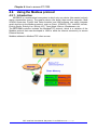
Using the Modbus protocol
4.2.1. Introduction
MODBUS is a master-slave bus system in which only one device (the master) actively
starts a transaction (query). The passive device (the slave) then sends a response. Most
SCADA Supervisor Control And Data Acuisition and HMI software can easily integrate
serial devices via the Modbus protocol, such as Citect, ICONICS, iFIX, InduSoft, Intouch,
Entivity Studio, Entivity Live, Entivity VLC, Trace Mode, Wizcon, Wonderware, etc.
The PET-7000 controller includes the Modbus/TCP protocol, which is a variation of the
Modbus protocol that was developed in 1999 to allow the Internet community to access
Ethernet devices.
Modbus address for Modbus/TCP client access.
PET-7000 DIO User Manual, May 2009, V1.00, EMH-013-10----------79
Chapter 4 How to access ET-7000
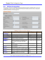
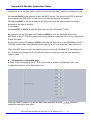
4.2.2. Function Codes Supported
Modbus function codes are different both the analog and digital types.
Table 4-1 PET-7000 Modbus Function Code
Modbus Command
(Hex)
Protocol Description
01
Read multiple coils status for DO
02
Read multiple input discrete for DI
03
Read multiple registers for AO
04
Read multiple input registers for AI
05
Write single coil for DO
06
Write single register for AO
0F
Force multiple coils for DO
10
Write multiple registers for AO
4.2.3. Modbus Register address table
In addition to the Web Configuration Page, the custom’s software that supports Modbus
protocol can be used to issue Modbus command to the PET-7000 module.
For more details regarding the Modbus address of the PET-7000 module, please refer to
Appendix C: Modbus Register Table.
PET-7000 DIO User Manual, May 2009, V1.00, EMH-013-10----------80
Chapter 5 I/O Pair Connection
5. I/O Pair Connection
The function is used to make a DI to DO pair through the Ethernet. The communication is
based on Modbus/TCP. Once the configuration is done, the PET-7000 can poll remote DI
status and then write to paired local DO constantly in the background.
Using the pair connection function, remote DI status can be transmitted to local DO over
the Ethernet without any programming skill.
Please refer to Sec. 3.5 Pair Connection for more details regarding the configuration of
the I/O pair connection.
PET-7000 DIO User Manual, May 2009, V1.00, EMH-013-10----------81
Chapter 6 Software Development Application
6. Software Development Application
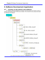
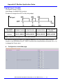
6.1.
Location of documents and software
The following diagram illustrates the location of all documents and software related to
Modbus applications for PET-7000 series modules. The relevant file can quickly be located
by referring to the diagram.
PET-7000 DIO User Manual, May 2009, V1.00, EMH-013-10----------82
Chapter 6 Software Development Application
There are a variety of applications that conform to the Modbus protocol, such as ActiveX,
LabVIEW, InduSoft, OPC Server, etc. are available for use on the/a Host PC. These
applications can be used to access the PET-7000 series module from the Host PC and
contain a number of helpful free demo programs and documents, which can be found on
the CD included in the shipping package, or can be downloaded from the ICP DAS web
site or FTP site.
When planning the development of a system, appropriate software solutions should be
chosen to suit different situations. The diagram (previous page) shows the relation
between the software solutions. Refer to the diagram to determine a solution that meets
your requirements.
PET-7000 DIO User Manual, May 2009, V1.00, EMH-013-10----------83
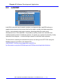
6.2.
Chapter 6 Software Development Application
LabVIEW
LabVIEW is the best way to acquire, analyze, and present data. LabVIEW delivers a
graphical development environment that can be used to quickly build data acquisition
quickly, instrumentation and control systems, boosting productivity and saving
development time. With LabVIEW, it is possible to quickly create user interfaces that
enable interactive control of software systems. To specify your system functionality, simply
assemble block diagram – a natural design notation for scientists and engineers.
The document containing the detailed instructions for linking to the PET-7000 using the
Modbus protocol is located on the shipped CD:
\NAPDOS\ET7000\Document\Application\LabVIEW or
ftp://ftp.icpdas.com/pub/cd/6000cd/napdos/et7000/document/application/labview
PET-7000 DIO User Manual, May 2009, V1.00, EMH-013-10----------84
Chapter 7 OPC Server
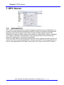
7. OPC Server
7.1.
Introduction
OPC (OLE for Process Control) is the first standard resulting from the collaboration of a
number of leading worldwide automation suppliers working in cooperation with Microsoft.
Originally based on Microsoft's OLE COM (Component Object Model) and DCOM
(Distributed Component Object Model) technologies, the specification defines a standard
set of objects, interfaces and methods for use in process control and manufacturing
automation applications to facilitate interoperability.
There are many different mechanisms provided by various vendors that allow access to a
variety of devices via specific applications. However, if an OPC server is provided for the
device, other applications will be able to access the OPC Server via the OPC interface.
PET-7000 DIO User Manual, May 2009, V1.00, EMH-013-10----------85
Chapter 7 OPC Server
7.2.
Procedure for using the OPC server
Step 1: Read the following documents
Readme.txt: contains the latest important information, including:
• A list of files contained on the shipped CD
Reversion.txt: contains the revision history information, including
• Bugs
• New modules supported
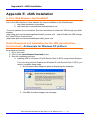
Step 2: Install the OPC server by executing:
CD:\NAPDOS\ET7000\Tools\Napopcsvr\NapOPCServer.exe
Note: If there is an older version of the Nap OPC Server installed on the PC, and
must be uninstalled before installing the new version.
Step 3: Read the manuals describing how to begin.
The NapOPCSvr.pdf is the user’s manual describing how to use the OPC server
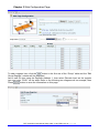
7.3.
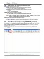
OPC Server Example using MODBUS protocol
The following is an example of accessing Digital input and output values from an ET-7000
Step 1: Connect the ET-7000 controller (refer to Sec. 1.5.2) and configure its network
settings (IP, Mask and Gateway - refer to Sec. 2.1)
Step 2: Run the OPC server
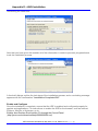
Step 3: Add/Create a new device and to search for I/O modules using Modbus /TCP
protocol
\
3.1
PET-7000 DIO User Manual, May 2009, V1.00, EMH-013-10----------86
Chapter 7 OPC Server
3.2
3.3
3.4
3.5
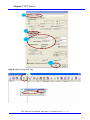
Step 4: New a Group and Tag
4.1
4.2
4.3
PET-7000 DIO User Manual, May 2009, V1.00, EMH-013-10----------87
Chapter 7 OPC Server
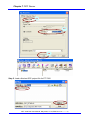
4.4
4.5
4.6
Step 5: Load a finished OPC project file for ET-7060
PET-7000 DIO User Manual, May 2009, V1.00, EMH-013-10----------88
Chapter 7 OPC Server
Note:
1. The OPC file for the ET-7060 is located at:
CD:\NAPDOS\ET7000\Document\Application\NAPOPC\ET-7060
PET-7000 DIO User Manual, May 2009, V1.00, EMH-013-10----------89
Chapter 8 SCADA
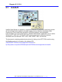
8. SCADA
SCADA stands for Supervisor Control And Data Acquisition. It is a production automation
and control system based on PCs
SCADA is wildly used in many fields e.g. power generation, water systems, the oil industry,
chemistry, the automobile industry. Different fields require different functions, but they all
have the common features:
•
Graphic interface
•
Process mimicking
•
Real time and historic trend data
•
Alarm system
•
Data acquisition and recording
•
Data analysis
•
Report generator
Accessing PET-7000 devices using SCADA software
SCADA software is able to access PET-7000 devices using Modbus communication
protocols, and can communicate without the need for other software drivers.
Famous SCADA software:
Citect, ICONICS, iFIX, InduSoft, Intouch, Entivity Studio, Entivity Live, Entivity VLC,
Trace Mode, Wizcon, Wonderware ... etc
In the following sections 3 popular brands of SCADA software are introduced together
with the detailed instructions in how use them to communicate with the PET-7000 series
module using the Modbus/TCP protocol.
PET-7000 DIO User Manual, May 2009, V1.00, EMH-013-10----------90
8.1.
Chapter 8 SCADA
InduSoft
InduSoft Web Studio is a powerful, integrated collection of automation tools that includes
all the building blocks needed to develop modern Human Machine Interfaces (HMI),
Supervisory Control and Data Acquisition (SCADA) systems, and embedded
instrumentation and control applications. InduSoft Web Studio’s application runs in native
Windows NT, 2000, XP, CE and CE .NET environments and conforms to industry
standards such as Microsoft .NET, OPC, DDE, ODBC, XML, and ActiveX.
The document containing detailed instructions for linking to the PET-7000 module using
the Modbus protocol is located on the shipped CD:
\NAPDOS\ET7000\Document\Application\InduSoft or
ftp://ftp.icpdas.com/pub/cd/6000cd/napdos/et7000/document/application/indusoft/
PET-7000 DIO User Manual, May 2009, V1.00, EMH-013-10----------91
8.2.
Chapter 8 SCADA
Citect
CitectSCADA is a fully integrated Human Machine Interface (HMI) / SCADA solution that
enables users to increase return on assets by delivering a highly scalable, reliable control
and monitoring system. Easy-to-use configuration tools and powerful features enable rapid
development and deployment of solutions for any size application.
The document containing detailed instructions for linking to the PET-7000 module using
the Modbus protocol is located on the shipped CD:
\NAPDOS\ET7000\Document\Application\Citect or
ftp://ftp.icpdas.com/pub/cd/6000cd/napdos/et7000/document/application/citect/
PET-7000 DIO User Manual, May 2009, V1.00, EMH-013-10----------92
8.3.
Chapter 8 SCADA
iFix
The document containing detailed instructions for linking to the PET-7000 module using
the Modbus protocol is located on the shipped CD:
\NAPDOS\ET7000\Document\Application\iFix or
ftp://ftp.icpdas.com/pub/cd/6000cd/napdos/et7000/document/application/ifix/
PET-7000 DIO User Manual, May 2009, V1.00, EMH-013-10----------93
Chapter 9 Troubleshooting and Technical Support
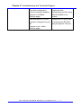
9. Troubleshooting and Technical Support
This chapter discusses methods of quickly diagnosing and fixing problems or errors
without having to contact ICP DAS.
When troubleshooting the following problems, please make sure that the module is
switched on, and confirm that the physical connections are correct (power cable, network
cable and serial cable)
Note that some unexplained errors might be caused by duplicate IP addresses on the
Network. Make sure that the IP address of your module is unique.
Table 9-1 Troubleshooting
Symptom/Problem
Possible cause
Solution
The RUN LED doesn’t light
Internal power has failed
Return the module for
repair.
The RUN LED indicator is
ON (light), but not flashing.
The module has possibly
crashed.
Reboot the module
Cannot communicate via
the Ethernet port, but the
ET-7000 is still operating.
The IP/Mask/Gateway
address isn’t within the IP
address range of the LAN.
Change the
IP/Mask/Gateway address
to match the LAN, or ask
the MIS administrator for
assistance.
The IP address has
restricted by the IP filter
settings
Check the IP filter setting
using the Web
configuration.
There are more than 30
TCP/IP connections.
Reboot the module.
Able to explore the web
page through port 80 using
a web browser, but the Web
HMI and Modbus/TCP
program cannot access the
module through port 502.
Port 502 has been restricted Consult your MIS
by the firewall.
administrator for assistance.
The Web HMI and
Modbus/TCP program can
The Port 502 has restricted
by the firewall.
Consult your MIS
administrator for assistance.
PET-7000 DIO User Manual, May 2009, V1.00, EMH-013-10----------94
Chapter 9 Troubleshooting and Technical Support
The Web Configuration
function has been disabled.
(Shown on the Basic
Settings page)
Enable the Web
Configuration function using
either the SMMI or the
console.
The Web server TCP port
Change the TCP port to 80
has been changed from port or reconnect the ET-7000
80
using the specific TCP port.
(Shown on the Basic
Settings page)
PET-7000 DIO User Manual, May 2009, V1.00, EMH-013-10----------95
Appendix A: Dimensions
Appendix A: Dimensions
PET-7000 DIO User Manual, May 2009, V1.00, EMH-013-10----------96
Appendix A: Dimensions
Wall Mount Bracket
0
0
.
8
6
9
.
3
0
5
.
5
9
.
0
5
.
1
0
0
.
1
3
0
6
.
4
2
0
0
.
5
5
2
.
5
1
4
5
.
2
R
0
1
.
5
3
7
.
1
5
8
.
7
2
0
0
.
8
PET-7000 DIO User Manual, May 2009, V1.00, EMH-013-10----------97
Appendix B: MiniOS7 utility
Appendix B: MiniOS7 utility
On occasions, ICP DAS will offer an update to the PET-7000 firmware or MiniOS7. The
MiniOS7 utility is used to easily update your software to the latest version. The MiniOS7
Utility is used for both essential configuration and for downloading programs into the PET7000 controller embedded in the ICPDAS MiniOS7 environment.
The MiniOS7 Utility program provides 3 main functions:
z Update the MiniOS7 image
z Download firmware to Flash memory
z Configure Ethernet and COM port settings
MiniOS7 utility location
The MiniOS7 utility is located in the
z CD:\ NAPDOS\ET7000\Tools\Tools for MiniOS7\MiniOS7_utility folder on the
enclosed CD or from
z ftp://ftp.icpdas.com/pub/cd/6000cd/napdos/et7000/tools/tools for
minios7/minios7_utility/
PET-7000 DIO User Manual, May 2009, V1.00, EMH-013-10----------98
Appendix B: MiniOS7 utility
Installation procedure
Step 1: Locate and run MiniOS7 utility.exe from the CD:
\NAPDOS\ET7000\Tools\Tools for MiniOS7\MiniOS7_utility directory.
Step 2:
After completing the installation, a new “ICPDAS” folder will be added to the
“programs” section of the start menu. The MiniOS7_utility files can be accessed by
clicking on this folder and then the 'MiniOS7 utility' folder. See the diagram below
for details.
Downloading firmware to the PET-7000 controller
The download procedure is as follows:
Step 1: From the Windows START menu, navigate to programs/ICPDAS/MiniOS7
Utility and locate the MiniOS7 utility' program.
Step 2: Click Search item on the Connect item of man menu.
Step 3: Double click the PET-7000 which you want to configure.
PET-7000 DIO User Manual, May 2009, V1.00, EMH-013-10----------99
Appendix B: MiniOS7 utility
Step 3: After a connection between the PET-7000 and PC has been successfully
established, the following screen will be displayed. (The total files on the selected
PET-7000 shows on the file list of right hand window)
Step 4: Right Click the file list on the right hand window and then click Quit Firmware
item from TCP/IP mode to UDP mode.
Notes:
z The default firmware of the PET-7000 series module is TCP/IP mode which
uses the TCP/IP protocol for communication. The Modbus/TCP protocol or
Web communication are constructed on this communication layer.
z The UDP mode is used to update the firmware and MiniOS7 image.
PET-7000 DIO User Manual, May 2009, V1.00, EMH-013-10----------100
Appendix B: MiniOS7 utility
PC File list
Step 5:
Click Erase Disk item of Command item of main menu.
PET-7000 DIO User Manual, May 2009, V1.00, EMH-013-10----------101
Appendix B: MiniOS7 utility
Step 6: A Confirm dialog notices whether all files will be deleted or not.
If Press “Yes” button, all files on the PET-7000 will be deleted. Please refer to the
picture below.
Notes:
z Before updating the firmware, you must delete all files existed on the PET-7000.
Step 5:
Locate the required file in the left hand window, then drag and drop this file to
the PET-7000. The figure below shows that the PET-7000 firmware has been
downloaded to the PET-7000 module.
PET-7000 DIO User Manual, May 2009, V1.00, EMH-013-10----------102
Appendix B: MiniOS7 utility
Notes:
z The PET-7000 firmware is a file named ET7Knnn.HEX, where ‘nnn’ is the version
number.
z The MiniOS7 utility is only a tool for the PET-7000 series module to update its
firmware, and the version of MiniOS7 utility must be V3.14 or later
Drag-and-Drop
PET-7000 DIO User Manual, May 2009, V1.00, EMH-013-10----------103
Appendix B: MiniOS7 utility
Notes:
To select multiple files, press and hold the CTRL or SHIFT keys while making
your/a selection and drag them to simultaneously download the files to the
PET-7000
z After completing the download, turn off the power to the PET-7000 and then
turn it back ON. This will cause the program to begin running the
autoexec.bat (the content of the autoexec.bat indicates which file in the PET7000 will run after rebooting). Alternatively, click the button to execute it.
z Please refer to the MiniOS7 utility help file for more details regarding the use
of MiniOS7 utility. This file is located in the ICPDAS MiniOS7_utility group in
the ‘Start’ menu, or can be accessed by clicking the icon at the top of the
MiniOS7 utility toolbar.
z
PET-7000 DIO User Manual, May 2009, V1.00, EMH-013-10----------104
Appendix C: Modbus Register Tables
Appendix C: MODBUS Register Tables
Modules Supported (PET-7000 series)
Name
PET-7060
Date
May 2009
Firmware
V1.10
Note
6 DO, 6 DI
6 Relay Output (Form A)
6 DI(Wet Contact (Sink, Source))
ET-7067
May 2009
V1.10
8 DO
8 Signal Relay, (Form A/Form C)
PET-7000 DIO User Manual, May 2009, V1.00, EMH-013-10----------105
Appendix C: Modbus Register Tables
Common Functions for all PET-7000 series modules
(0xxxx) DO address
Begin
Points
Description
address
126
1
Recover all I/O default settings
Registers
Range
per Point
1
1=recover
Access
Type
W (Pulse)
127
1
Recover all web default settings
1
1=recover
W (Pulse)
128
1
ID default settings
1
1=recover
W (Pulse)
129
1
Web Enable/Disable
1
1=recover
W (Pulse)
133
1
Reboot the PET-7000
1
1=reboot
W (Pulse)
(3xxxx) AI address
Begin
Points
Description
address
150
1
OS image version
Registers
Range
per Point
1
123 means
version=1.2.3
Access
Type
R
151
1
Total Firmware version
1
123 means
version=1.2.3
R
158
1
Modbus communication status
1
0= No Error
-1= CRC error
-2= Timeout
R
160
1
Pair Connection
1
0=Normal
1=Timeout
2=Disconnected
R
PET-7000 DIO User Manual, May 2009, V1.00, EMH-013-10----------106
Appendix C: Modbus Register Tables
(4xxxx) AO address
Begin
Points
Description
address
255
1
CPU reset status
Registers
Range
per Point
1
1= by power on
2= by 0.8 second WDT
3= by Reset command
Access
Type
R/W
256
1
CPU reset events
1
How many CPU reset
events has happened?
When CPU is reset by
one of the situations
described in register
555, the event
increases one count.
R/W/E
257
1
Set host watch dog timer
1
<5: Disabled 5~65535:
Enabled (unit: second)
(default=0)
When the PET-7000
loses communication
with PC more than the
WDT setting, DO and
AO go to their safe
values and host WDT
events plus 1 count.
R/W/E
258
1
Host WDT events
1
How many host WDT
events has happened
after CPU reset?
R/W
259
1
Module name
4
8 ASCII characters
R
263
1
Module nick name
16
16 ASCII characters
R/W/E
PET-7000 DIO User Manual, May 2009, V1.00, EMH-013-10----------107
Appendix C: Modbus Register Tables
PET-7060 I/O Address Mapping
Modbus Address (Base 0)
00000
00001
00002
00003
00004
00005
DO Channel (Base 0)
5
4
DI Channel (Base 0)
3
2
1
0
5 4 3 2 1 0
Modbus Address (Base 0)
10005
10004
10003
10002
10001
10000
PET-7000 DIO User Manual, May 2009, V1.00, EMH-013-10----------108
Appendix C: Modbus Register Tables
PET-7060 Counter Address Mapping
Counter channel (Base 0)
Modbus Address (Base 0)
5 4 3 2 1 0
30026
30024
30022
30020
30018
30016
PET-7000 DIO User Manual, May 2009, V1.00, EMH-013-10----------109
Appendix C: Modbus Register Tables
Detailed Modbus Address Table for PET-7060
(0xxxx) DO address
Begin
Points
Description
address
0 0~5 Digital Output
Registers
Range
per Point
1
0=off 1=on
Access
Type
R/W
32
1
Clear all DI latched status (high)
1
1=clear
W (Pulse)
33
1
Clear all DI latched status (low)
1
1=clear
W (Pulse)
34
0~5
1
1=clear
W (Pulse)
150
1
Clear low speed (500Hz) digital
counter
Enable all DI latched status
(high/low)
1
0=disable
1=enable
(default=0)
R/W/E
151
0~5
Enable low speed (500Hz)
digital counter
1
0=disable
1=enable
(default=0)
R/W/E
231
1
1
1=write
W (Pulse)
232
1
1
1=write
W (Pulse)
235
0~5
Write DO Power on value to
EEPROM
Write DO Safe value to
EEPROM
Power on value for DO
1
267
0~5
Safe value for DO
1
0=off
1=on
(default=0)
0=off
1=on
(default=0)
R/W/E
R/W/E
(1xxxx) DI address
Begin
Points
Description
address
0 0~5 Digital Input
Registers
Range
per Point
1
0=off 1=on
Access
Type
R
32
0~5
Digital latched status (high)
1
0=no 1=latched
R
64
0~5
Digital latched status (low)
1
0=no 1=latched
R
PET-7000 DIO User Manual, May 2009, V1.00, EMH-013-10----------110
Appendix C: Modbus Register Tables
(3xxxx) AI address
Begin
Points
Description
address
16 0~5 Low speed (500Hz) digital
counter
Registers
Range
per Point
2
0~4294967296
Access
Type
R
(3xxxx) AI address (Static Channel Number Value)
Begin
address
Points
Description
Registers
per Point
Value
Access
Type
100
1
DI (channel number)
1
6
R
101
1
1
6
R
110
1
DI high/low latch (channel
number)
DO (channel number)
1
6
R
111
1
1
6
R
112
1
1
6
R
121
1
1
6
R
Power on value for DO (channel
number)
Safe value for DO (channel
number)
Low speed counter (500Hz)
(channel number)
(4xxxx) AO address
Begin
Points
Description
address
50 0~5 Preset value for low speed
(500Hz) digital counter
Registers
Range
per Point
2
0~4294967296
(default=0)
PET-7000 DIO User Manual, May 2009, V1.00, EMH-013-10----------111
Access
Type
R/W/E
Appendix C: Modbus Register Tables
PET-7066 I/O Address Mapping
Modbus Address (Base 0)
00000
00001
00002
00003
5
4
3
2
1
0
DO Channel (Base 0)
00005
6
00004
7
DO Channel (Base 0)
00006
00007
PET-7000 DIO User Manual, May 2009, V1.00, EMH-013-10----------112
Appendix C: Modbus Register Tables
Detailed Modbus Address Table for PET-7066
(0xxxx) DO address
Begin
Points
Description
address
0 0~7 Digital Output
231
1
232
1
235
267
Registers
Range
per Point
1
0=off 1=on
Access
Type
R/W
1
1=write
W (Pulse)
1
1=write
W (Pulse)
0~7
Write DO Power on value to
EEPROM
Write DO Safe value to
EEPROM
Power on value for DO
1
0~7
Safe value for DO
1
0=off
1=on
(default=0)
0=off
1=on
(default=0)
R/W/E
R/W/E
(3xxxx) AI address (Static Channel Number Value)
Begin
address
Points
Description
Registers
per Point
Value
Access
Type
110
1
DO (channel number)
1
8
R
111
1
1
8
R
112
1
Power on value for DO (channel
number)
Safe value for DO (channel
number)
1
8
R
PET-7000 DIO User Manual, May 2009, V1.00, EMH-013-10----------113
Appendix C: Modbus Register Tables
PET-7067 I/O Address Mapping
Modbus channel (Base 0)
00000
00001
00002
00003
00004
00005
4
3
2
D0 Address (Base 0)
6
7
DO Address (Base 0)
5
1
0
Modbus channel (Base 0)
00006
00007
PET-7000 DIO User Manual, May 2009, V1.00, EMH-013-10----------114
Appendix C: Modbus Register Tables
Detailed Modbus Address Table for PET-7067
(0xxxx) DO address
Begin
Points
Description
address
0 0~7 Digital Output
231
1
232
1
235
267
Registers
Range
per Point
1
0=off 1=on
Access
Type
R/W
1
1=write
W (Pulse)
1
1=write
W (Pulse)
0~7
Write DO Power on value to
EEPROM
Write DO Safe value to
EEPROM
Power on value for DO
1
0~7
Safe value for DO
1
0=off
1=on
(default=0)
0=off
1=on
(default=0)
R/W/E
R/W/E
(3xxxx) AI address (Static Channel Number Value)
Begin
address
Points
Description
Registers
per Point
Value
Access
Type
110
1
DO (channel number)
1
8
R
111
1
1
8
R
112
1
Power on value for DO (channel
number)
Safe value for DO (channel
number)
1
8
R
PET-7000 DIO User Manual, May 2009, V1.00, EMH-013-10----------115
Appendix C: Modbus Register Tables
PET-7042 I/O Address Mapping
PET-7000 DIO User Manual, May 2009, V1.00, EMH-013-10----------116
Appendix C: Modbus Register Tables
Detailed Modbus Address Table for PET-7042
(0xxxx) DO address
Begin
Points
Description
address
0 0~15 Digital Output
231
1
232
1
235
267
Registers
Range
per Point
1
0=off 1=on
Access
Type
R/W
1
1=write
W (Pulse)
1
1=write
W (Pulse)
0~15
Write DO Power on value to
EEPROM
Write DO Safe value to
EEPROM
Power on value for DO
1
0~15
Safe value for DO
1
0=off
1=on
(default=0)
0=off
1=on
(default=0)
R/W/E
R/W/E
(3xxxx) AI address (Static Channel Number Value)
Begin
address
Points
Description
Registers
per Point
Value
Access
Type
110
1
DO (channel number)
1
16
R
111
1
1
16
R
112
1
Power on value for DO (channel
number)
Safe value for DO (channel
number)
1
16
R
PET-7000 DIO User Manual, May 2009, V1.00, EMH-013-10----------117
Appendix C: Modbus Register Tables
PET-7044 I/O Address Mapping
PET-7000 DIO User Manual, May 2009, V1.00, EMH-013-10----------118
Appendix C: Modbus Register Tables
PET-7044 Counter Address Mapping
Modbus Address (Base 0)
30020
30018
30016
30022
30024
30026
30028
30030
2 1 0
3 4 5 6 7 DI Channel (Base 0)
PET-7000 DIO User Manual, May 2009, V1.00, EMH-013-10----------119
Appendix C: Modbus Register Tables
Detailed Modbus Address Table for PET-7044
(0xxxx) DO address
Begin
Points
Description
address
0 0~7 Digital Output
Registers
Range
per Point
1
0=off 1=on
Access
Type
R/W
32
1
Clear all DI latched status (high)
1
1=clear
W (Pulse)
33
1
Clear all DI latched status (low)
1
1=clear
W (Pulse)
34
0~7
1
1=clear
W (Pulse)
150
1
Clear low speed (500Hz) digital
counter
Enable all DI latched status
(high/low)
1
0=disable
1=enable
(default=0)
R/W/E
151
0~7
Enable low speed (500Hz)
digital counter
1
0=disable
1=enable
(default=0)
R/W/E
231
1
1
1=write
W (Pulse)
232
1
1
1=write
W (Pulse)
235
0~7
Write DO Power on value to
EEPROM
Write DO Safe value to
EEPROM
Power on value for DO
1
267
0~7
Safe value for DO
1
0=off
1=on
(default=0)
0=off
1=on
(default=0)
R/W/E
R/W/E
(1xxxx) DI address
Begin
Points
Description
address
0 0~7 Digital Input
Registers
Range
per Point
1
0=off 1=on
Access
Type
R
32
0~7
Digital latched status (high)
1
0=no 1=latched
R
64
0~7
Digital latched status (low)
1
0=no 1=latched
R
PET-7000 DIO User Manual, May 2009, V1.00, EMH-013-10----------120
Appendix C: Modbus Register Tables
(3xxxx) AI address
Begin
Points
Description
address
16 0~7 Low speed (500Hz) digital
counter
Registers
Range
per Point
2
0~4294967296
Access
Type
R
(3xxxx) AI address (Static Channel Number Value)
Begin
address
Points
Description
Registers
per Point
Value
Access
Type
100
1
DI (channel number)
1
8
R
101
1
1
8
R
110
1
DI high/low latch (channel
number)
DO (channel number)
1
8
R
111
1
1
8
R
112
1
1
8
R
121
1
1
8
R
Power on value for DO (channel
number)
Safe value for DO (channel
number)
Low speed counter (500Hz)
(channel number)
(4xxxx) AO address
Begin
Points
Description
address
50 0~7 Preset value for low speed
(500Hz) digital counter
Registers
Range
per Point
2
0~4294967296
(default=0)
PET-7000 DIO User Manual, May 2009, V1.00, EMH-013-10----------121
Access
Type
R/W/E
Appendix C: Modbus Register Tables
PET-7050 I/O Address Mapping
Modbus Address (Base 0)
00000
00001
00002
00003
00004
00005
54 32 10
543 210
DO Channel (Base 0)
DI Channel (Base 0)
10005
10004
10003
10002
10001
10000
6
DI Channel (Base 0)
7
10006
10007
10008
10009
10010
10011
8
9
10
11
PET-7000 DIO User Manual, May 2009, V1.00, EMH-013-10----------122
Appendix C: Modbus Register Tables
PET-7050 Counter Address Mapping
Modbus Address (Base 0)
30016
30018
30020
30022
30024
30026
DO Channel (Base 0)
543 210
6
DI Channel (Base 0)
7
30028
30030
30032
30034
30036
30038
8
9
10
11
PET-7000 DIO User Manual, May 2009, V1.00, EMH-013-10----------123
Appendix C: Modbus Register Tables
Detailed Modbus Address Table for PET-7050
(0xxxx) DO address
Begin
Points
Description
address
0 0~5 Digital Output
Registers
Range
per Point
1
0=off 1=on
Access
Type
R/W
32
1
Clear all DI latched status (high)
1
1=clear
W (Pulse)
33
1
Clear all DI latched status (low)
1
1=clear
W (Pulse)
34
0~5
1
1=clear
W (Pulse)
150
1
Clear low speed (500Hz) digital
counter
Enable all DI latched status
(high/low)
1
0=disable
1=enable
(default=0)
R/W/E
151
0~5
Enable low speed (500Hz)
digital counter
1
0=disable
1=enable
(default=0)
R/W/E
231
1
1
1=write
W (Pulse)
232
1
1
1=write
W (Pulse)
235
0~5
Write DO Power on value to
EEPROM
Write DO Safe value to
EEPROM
Power on value for DO
1
267
0~5
Safe value for DO
1
0=off
1=on
(default=0)
0=off
1=on
(default=0)
R/W/E
R/W/E
(1xxxx) DI address
Begin
Points
Description
address
0 0~11 Digital Input
Registers
Range
per Point
1
0=off 1=on
Access
Type
R
32
0~11
Digital latched status (high)
1
0=no 1=latched
R
64
0~11
Digital latched status (low)
1
0=no 1=latched
R
PET-7000 DIO User Manual, May 2009, V1.00, EMH-013-10----------124
Appendix C: Modbus Register Tables
(3xxxx) AI address
Begin
Points
Description
address
16 0~11 Low speed (500Hz) digital
counter
Registers
Range
per Point
2
0~4294967296
Access
Type
R
(3xxxx) AI address (Static Channel Number Value)
Begin
address
Points
Description
Registers
per Point
Value
Access
Type
100
1
DI (channel number)
1
12
R
101
1
1
12
R
110
1
DI high/low latch (channel
number)
DO (channel number)
1
6
R
111
1
1
6
R
112
1
1
6
R
121
1
1
12
R
Power on value for DO (channel
number)
Safe value for DO (channel
number)
Low speed counter (500Hz)
(channel number)
(4xxxx) AO address
Begin
Points
Description
address
50 0~11 Preset value for low speed
(500Hz) digital counter
Registers
Range
per Point
2
0~4294967296
(default=0)
PET-7000 DIO User Manual, May 2009, V1.00, EMH-013-10----------125
Access
Type
R/W/E
Appendix C: Modbus Register Tables
PET-7051 I/O Address Mapping
PET-7000 DIO User Manual, May 2009, V1.00, EMH-013-10----------126
Appendix C: Modbus Register Tables
PET-7051 Counter Address Mapping
Modbus Address (Base 0)
30016
30018
30020
30022
30024
30026
30028
30030
12 11 10 9 8
30040
30038
30036
30034
30032
30042
30044
30046
76 54 32 10
13
14
15
DI Channel (Base 0)
DI Channel (Base 0)
PET-7000 DIO User Manual, May 2009, V1.00, EMH-013-10----------127
Appendix C: Modbus Register Tables
Detailed Modbus Address Table for PET-7051
(0xxxx) DO address
Begin
Registers
Points
Description
Range
address
per Point
32
1
Clear all DI latched status (high)
1
1=clear
Access
Type
W (Pulse)
33
1
Clear all DI latched status (low)
1
1=clear
W (Pulse)
34
0~15
Clear low speed (500Hz) digital
counter
1
1=clear
W (Pulse)
150
1
Enable all DI latched status
(high/low)
1
0=disable
1=enable
(default=0)
R/W/E
151
0~15
Enable low speed (500Hz)
digital counter
1
0=disable
1=enable
(default=0)
R/W/E
(1xxxx) DI address
Begin
Points
Description
address
0 0~15 Digital Input
Registers
Range
per Point
1
0=off 1=on
Access
Type
R
32
0~15
Digital latched status (high)
1
0=no 1=latched
R
64
0~15
Digital latched status (low)
1
0=no 1=latched
R
(3xxxx) AI address
Begin
Points
Description
address
16 0~15 Low speed (500Hz) digital
counter
Registers
Range
per Point
2
0~4294967296
Access
Type
R
(3xxxx) AI address (Static Channel Number Value)
Begin
address
Points
Description
Registers
per Point
Value
Access
Type
100
1
DI (channel number)
1
16
R
101
1
1
16
R
121
1
DI high/low latch (channel
number)
Low speed counter (500Hz)
(channel number)
1
16
R
PET-7000 DIO User Manual, May 2009, V1.00, EMH-013-10----------128
Appendix C: Modbus Register Tables
(4xxxx) AO address
Begin
Points
Description
address
50 0~15 Preset value for low speed
(500Hz) digital counter
Registers
Range
per Point
2
0~4294967296
(default=0)
PET-7000 DIO User Manual, May 2009, V1.00, EMH-013-10----------129
Access
Type
R/W/E
Appendix C: Modbus Register Tables
PET-7052 I/O Address Mapping
PET-7000 DIO User Manual, May 2009, V1.00, EMH-013-10----------130
Appendix C: Modbus Register Tables
PET-7052 Counter Address Mapping
PET-7000 DIO User Manual, May 2009, V1.00, EMH-013-10----------131
Appendix C: Modbus Register Tables
Detailed Modbus Address Table for PET-7052
(0xxxx) DO address
Begin
Points
Description
address
0 0~7 Digital Output
Registers
Range
per Point
1
0=off 1=on
Access
Type
R/W
32
1
Clear all DI latched status (high)
1
1=clear
W (Pulse)
33
1
Clear all DI latched status (low)
1
1=clear
W (Pulse)
34
0~7
1
1=clear
W (Pulse)
150
1
Clear low speed (500Hz) digital
counter
Enable all DI latched status
(high/low)
1
0=disable
1=enable
(default=0)
R/W/E
151
0~7
Enable low speed (500Hz)
digital counter
1
0=disable
1=enable
(default=0)
R/W/E
231
1
1
1=write
W (Pulse)
232
1
1
1=write
W (Pulse)
235
0~7
Write DO Power on value to
EEPROM
Write DO Safe value to
EEPROM
Power on value for DO
1
267
0~7
Safe value for DO
1
0=off
1=on
(default=0)
0=off
1=on
(default=0)
R/W/E
R/W/E
(1xxxx) DI address
Begin
Points
Description
address
0 0~7 Digital Input
Registers
Range
per Point
1
0=off 1=on
Access
Type
R
32
0~7
Digital latched status (high)
1
0=no 1=latched
R
64
0~7
Digital latched status (low)
1
0=no 1=latched
R
PET-7000 DIO User Manual, May 2009, V1.00, EMH-013-10----------132
Appendix C: Modbus Register Tables
(3xxxx) AI address
Begin
Points
Description
address
16 0~7 Low speed (500Hz) digital
counter
Registers
Range
per Point
2
0~4294967296
Access
Type
R
(3xxxx) AI address (Static Channel Number Value)
Begin
address
Points
Description
Registers
per Point
Value
Access
Type
100
1
DI (channel number)
1
8
R
101
1
1
8
R
110
1
DI high/low latch (channel
number)
DO (channel number)
1
8
R
111
1
1
8
R
112
1
1
8
R
121
1
1
8
R
Power on value for DO (channel
number)
Safe value for DO (channel
number)
Low speed counter (500Hz)
(channel number)
(4xxxx) AO address
Begin
Points
Description
address
50 0~7 Preset value for low speed
(500Hz) digital counter
Registers
Range
per Point
2
0~4294967296
(default=0)
PET-7000 DIO User Manual, May 2009, V1.00, EMH-013-10----------133
Access
Type
R/W/E
Appendix C: Modbus Register Tables
PET-7053 I/O Address Mapping
Modbus Address (Base 0)
00000
00001
00002
00003
00004
00005
00006
00007
12 11 10 9 8 7 6 5 4 3 2 1 0
00012
00011
00010
00009
00008
00013
00014
00015
13
14
15
DI Channel (Base 0)
DI Channel (Base 0)
PET-7000 DIO User Manual, May 2009, V1.00, EMH-013-10----------134
Appendix C: Modbus Register Tables
PET-7053 Counter Address Mapping
Modbus Address (Base 0)
30016
30018
30020
30022
30024
30026
30028
30030
12 11 10 9 8 7 6 5 4 3 2 1 0
30040
30038
30036
30034
30032
30042
30044
30046
13
14
15
DI Channel (Base 0)
DI Channel (Base 0)
PET-7000 DIO User Manual, May 2009, V1.00, EMH-013-10----------135
Appendix C: Modbus Register Tables
Detailed Modbus Address Table for PET-7053
(0xxxx) DO address
Begin
Registers
Points
Description
Range
address
per Point
32
1
Clear all DI latched status (high)
1
1=clear
Access
Type
W (Pulse)
33
1
Clear all DI latched status (low)
1
1=clear
W (Pulse)
34
0~15
Clear low speed (500Hz) digital
counter
1
1=clear
W (Pulse)
150
1
Enable all DI latched status
(high/low)
1
0=disable
1=enable
(default=0)
R/W/E
151
0~15
Enable low speed (500Hz)
digital counter
1
0=disable
1=enable
(default=0)
R/W/E
(1xxxx) DI address
Begin
Points
Description
address
0 0~15 Digital Input
Registers
Range
per Point
1
0=off 1=on
Access
Type
R
32
0~15
Digital latched status (high)
1
0=no 1=latched
R
64
0~15
Digital latched status (low)
1
0=no 1=latched
R
(3xxxx) AI address
Begin
Points
Description
address
16 0~15 Low speed (500Hz) digital
counter
Registers
Range
per Point
2
0~4294967296
Access
Type
R
(3xxxx) AI address (Static Channel Number Value)
Begin
address
Points
Description
Registers
per Point
Value
Access
Type
100
1
DI (channel number)
1
16
R
101
1
1
16
R
121
1
DI high/low latch (channel
number)
Low speed counter (500Hz)
(channel number)
1
16
R
PET-7000 DIO User Manual, May 2009, V1.00, EMH-013-10----------136
Appendix C: Modbus Register Tables
(4xxxx) AO address
Begin
Points
Description
address
50 0~15 Preset value for low speed
(500Hz) digital counter
Registers
Range
per Point
2
0~4294967296
(default=0)
PET-7000 DIO User Manual, May 2009, V1.00, EMH-013-10----------137
Access
Type
R/W/E
Appendix C: Modbus Register Tables
PET-7065 I/O Address Mapping
Modbus Address (Base 0)
00000
00001
00002
00003
5
4
3
2
1
0
DO Channel (Base 0)
00005
00004
5 43 21 0
DI Channel (Base 0)
10005
10004
10003
10002
10001
10000
PET-7000 DIO User Manual, May 2009, V1.00, EMH-013-10----------138
Appendix C: Modbus Register Tables
PET-7065 Counter Address Mapping
Modbus Address (Base 0)
5 4 321 0
DI Channel (Base 0)
30016
30018
30020
30022
30024
30026
PET-7000 DIO User Manual, May 2009, V1.00, EMH-013-10----------139
Appendix C: Modbus Register Tables
Detailed Modbus Address Table for PET-7065
(0xxxx) DO address
Begin
Points
Description
address
0 0~5 Digital Output
Registers
Range
per Point
1
0=off 1=on
Access
Type
R/W
32
1
Clear all DI latched status (high)
1
1=clear
W (Pulse)
33
1
Clear all DI latched status (low)
1
1=clear
W (Pulse)
34
0~5
1
1=clear
W (Pulse)
150
1
Clear low speed (500Hz) digital
counter
Enable all DI latched status
(high/low)
1
0=disable
1=enable
(default=0)
R/W/E
151
0~5
Enable low speed (500Hz)
digital counter
1
0=disable
1=enable
(default=0)
R/W/E
231
1
1
1=write
W (Pulse)
232
1
1
1=write
W (Pulse)
235
0~5
Write DO Power on value to
EEPROM
Write DO Safe value to
EEPROM
Power on value for DO
1
267
0~5
Safe value for DO
1
0=off
1=on
(default=0)
0=off
1=on
(default=0)
R/W/E
R/W/E
(1xxxx) DI address
Begin
Points
Description
address
0 0~5 Digital Input
Registers
Range
per Point
1
0=off 1=on
Access
Type
R
32
0~5
Digital latched status (high)
1
0=no 1=latched
R
64
0~5
Digital latched status (low)
1
0=no 1=latched
R
PET-7000 DIO User Manual, May 2009, V1.00, EMH-013-10----------140
Appendix C: Modbus Register Tables
(3xxxx) AI address
Begin
Points
Description
address
16 0~5 Low speed (500Hz) digital
counter
Registers
Range
per Point
2
0~4294967296
Access
Type
R
(3xxxx) AI address (Static Channel Number Value)
Begin
address
Points
Description
Registers
per Point
Value
Access
Type
100
1
DI (channel number)
1
8
R
101
1
1
8
R
110
1
DI high/low latch (channel
number)
DO (channel number)
1
8
R
111
1
1
8
R
112
1
1
8
R
121
1
1
8
R
Power on value for DO (channel
number)
Safe value for DO (channel
number)
Low speed counter (500Hz)
(channel number)
(4xxxx) AO address
Begin
Points
Description
address
50 0~5 Preset value for low speed
(500Hz) digital counter
Registers
Range
per Point
2
0~4294967296
(default=0)
Access
Type
R/W/E
Notes:
1. All address in the protocol definition is started from zero. (Base 0)
2. Definition of the Modbus Register table
Access Type:
R: means the value of the address is only readable.
W: means the value of the address can be written.
W (Pulse): means the value of the address can be written but the value will Reset
at next loop scan.
E: means the value of the address will be saved into the EEPROM
PET-7000 DIO User Manual, May 2009, V1.00, EMH-013-10----------141
Appendix D: Modbus Application Notes
Appendix D: Modbus Application Notes
Dual Watchdog
Dual Watchdog consists of Module Watchdog and Host Watchdog.
The Module Watchdog is a built-in hardware circuit that will reset the CPU module if a failure
occurs in either the hardware or the software. If the application does not refresh the watchdog
timer within 0.8 seconds, the watchdog circuit will initiate a reset of the CPU.
The Host Watchdog is a software function that can be used to monitor the operating status
of the host. Its purpose is to prevent network communication problems or a host failure. If the
Watchdog timeout interval expires, the module will return all outputs to a predefined Safe
value (Refer to the Safe Value application note), which can prevent the controlled target from
unexpected situation.
AO address
40257 of the ET-7000 series Modbus register is the
address of the Host Watchdog timer, and will be stored into EEPROM. The WDT function
PET-7000 DIO User Manual, May 2009, V1.00, EMH-013-10----------142
Appendix D: Modbus Application Notes
will be disabled if the value is set to less then 5 seconds.
Power ON Value
If the ET-7000 series module is reset, the output of the module is set to the predefined Power
ON Value for the DO and AO channels.
DO address 00235 of the ET-7000 series Modbus register is the first address of the Power
ON value, and the total number of channels depend on the type of module.
For example:
Addresses 00235 to 00240 records the Power ON value for the 6-Channel ET-7060.
Be careful to set the ON value to DO address 00231 to write the DO Power ON value to the
EEPROM of the ET-7000 DO module after using Modbus commands (05 or 15) to change the
Power ON value.
Set the ON value to DO address, 00233 to write the AO Power ON value to the EEPROM of
the ET-7000 AO module after using the Modbus commands (06 or 16) to change the Power
ON value.
z Configuration via Web page
Browse to the homepage of the ET-7000, and click the “Modbus I/O Settings” link in the
Configuration Section of the Main Menu tree.
Click the ON/OFF radio box to set the power ON/OFF value and then click the
button to enable the settings to take effect.
Safe Value
If the time of the Host PC losing Modbus/TCP communication with the module is greater than
the host WatchDog timer setting (called WDT timeout), the output of the Digital and Analog
PET-7000 DIO User Manual, May 2009, V1.00, EMH-013-10----------143
Appendix D: Modbus Application Notes
channels is set to the Safe Value, and the count of the host WDT events is increased by one.
AO address 40258 is the address of the Host WDT events. The value of the WDT events will
be not stored into EEPROM, and will return to 0 after the module is rebooted.
DO address 00267 is the first address of the Safe value and the total number of channels
depends on the type of module.
For example:
Address 00267 to 00272 records the Safe value for the 6-Channel ET-7060.
Be careful to set the ON value to DO address 00232 to write the DO Safe value to the
EEPROM of the ET-7000 DO module after using Modbus commands (05 or 15) to change the
Power ON value.
Set the ON value to DO address 00234 to write the AO Safe value to the EEPROM of the ET7000 AO module after using Modbus commands (06 or 16) to change the Power ON value.
While the WDT timeout is set, the module can also receive the Modbus/TCP commands (05,
06, 15 and 16) to change the DO or AO value without needing to clear the host watchdog
timeout value.
z Configuration via the Web page
Browse to the homepage of the ET-7000, and click the “Modbus I/O Settings” link in the
Configuration Section of the Main Menu tree.
Click the ON/OFF radio box to set the Safe value and then click the
enable the settings to take effect.
PET-7000 DIO User Manual, May 2009, V1.00, EMH-013-10----------144
button to
Appendix D: Modbus Application Notes
z View the Power ON/Safe Value via the Web page
Click the “Web HMI” link in the Web HMI Section of the Main Menu tree.
PET-7000 DIO User Manual, May 2009, V1.00, EMH-013-10----------145
Appendix D: Modbus Application Notes
Digital Input High/Low Latch
DI Latch
Function
Enable Latch
Clear ALL
Latch (High)
Clear ALL
Latch (Low)
Latch Status
(High)
Latch Status
(Low)
Address
00150
00032
00033
10032~1XXXX
10064~1XXXX
XXXX: Depends on the type of ET-7000 series module
For example: The user connects a key switch to the digital input channel of a digital input
module and wants to read the keystrokes. The key input is a pulse digital input signal, and the
user will miss the stroke. When reading the DI status for DI address 10000 by Modbus
command 02 in A and B position, the response will be that
no keystroke has been made and the keystroke information will be lost. In contrast, reading
the latched low digital input at DI address 10064 using Modbus command 02 will solve this
problem. When issuing 02 command in A and B position, the response denotes that there has
been a low pulse between the A and B position indicating a keystroke.
z
Configuration via the Web page
PET-7000 DIO User Manual, May 2009, V1.00, EMH-013-10----------146
Appendix D: Modbus Application Notes
Digital Input Counter
Low Speed Counter: 500Hz
Valid Range: 0~4294967296 counters
DI status is changed from OFF to ON (rising edge).
DI Counter
Functions
Enable Counter
Clear Counter
Counter Value
Preset value for
Counter
Address
00151~0XXXX
00034~0XXXX
30016~3XXXX
40050~4XXXX
XXXX: Depends on the type of ET-7000 series module
Be careful to set the ON value to DO address 00318 to save the Preset value for the DI
counter to the EEPROM of the ET-7000 DI module after using Modbus commands (06 or 16)
to change the Preset value.
z
Configuration via the Web page
PET-7000 DIO User Manual, May 2009, V1.00, EMH-013-10----------147
Appendix D: Modbus Application Notes
z View the DI Counter and Latch status via the Web page
Click the “Web HMI” link in the Web HMI Section of the Main Menu tree.
The DI Counter value is shown in each field of the “Counter & Clear” column, and the can be
cleared by clicking the button on the page.
Æ
On clicking the button, the counter value will return to 0, such as
(As long as a preset value for the DI Counter isn’t set).
If the preset value for the DI Counter is set to 2, when the button is clicked and the counter
value will return to the preset value, such as
Æ
.
The DI latch status is shown in each field of the “High Latch/Low Latch” column.
The entire of DI/DI Counter/Latch status data on this page will be updated automatically for a
period time.
PET-7000 DIO User Manual, May 2009, V1.00, EMH-013-10----------148
Appendix E: JAVA Installation
Appendix E: JAVA Installation
Is Your Web Browser Java Enabled?
Link to the URLs below to check whether the Java is available on the Web Browser.
1. http://www.javatester.org/enabled
2. http://www.java.com/en/download/help/testvm.xml
If Java is installed, but not enabled, Sun has instructions to enable the JRE through your Web
browser
(http://www.java.com/en/download/help/enable_browser.xml) and to Enable the JRE through
the "Java?Plug-in Control Panel".
(http://www.java.com/en/download/help/enable_panel.xml)
Online Download and Installation for the JRE (Java Runtime
Environment)- An Example for Windows XP platform
Download and Install
1. Go to Java.com
2. Click on the Java Software Download button.
3. Start the installation process:
a. Installing JRE on Windows XP with Service Pack 2 (SP2) using Internet Explorer
If you are using Internet Explorer on Windows XP with Service Pack 2 (SP2), you
need to complete these steps:
1. An Information Bar dialog box pops up displaying this message:
2. Click OK. A toolbar displays this message:
PET-7000 DIO User Manual, May 2009, V1.00, EMH-013-10----------149
Appendix E: JAVA Installation
3. Click on the toolbar and choose: Install ActiveX Control....
A Security Warning dialog box appears.
4. Click Install to start the installation process.
4. The download process starts. During the download, a progress window lets you know the
estimated time remaining for the download to finish. The download can take anywhere
from a few seconds on a fast Internet connection to half an hour or more on a very slow
connection. Once the download is over the installation process will start automatically.
PET-7000 DIO User Manual, May 2009, V1.00, EMH-013-10----------150
Appendix E: JAVA Installation
5. The JRE installation starts:
The installer "unpacks" the files needed to continue. A dialog box tracks this process, which
takes less than a minute. After briefly displaying a Java logo splash screen, the installer
presents the license agreement.
The installer displays a Setup Type screen that allows you to choose either a typical or custom
setup. We recommend that you choose the Typical option (the default selection) unless you are
an advanced user who wants more precise control over the components that will be installed.
After ensuring that the Typical setup is selected, click the Next button to continue with the
installation.
The Java Runtime Environment 5.0 Update 5 – Google Programs dialog box will appear. By
default Google Toolbar for Internet Explorer is checked. Click Next button. This will start
installing selected programs features including the JRE on your system.
Note: You can choose to install or ignore this useful additional program by checking or
PET-7000 DIO User Manual, May 2009, V1.00, EMH-013-10----------151
Appendix E: JAVA Installation
unchecking the check box.
Now that you have given the installer all of the information it needs to proceed, progress boxes
track the installation process.
A few brief dialogs confirm the last steps of the installation process, and a concluding message
appears with the confirmation "Installation Completed OK."
Enable and Configure
Once the installation is complete, ensure that the JRE is enabled and configured properly for
applets and applications. For instructions to enable the JRE for the browser, such as Internet
Explorer, Mozilla, or Netscape, go to:
Enable Java Runtime Environment 5.0 through the Control Panel
(http://java.com/en/download/help/5000020200.xml)
PET-7000 DIO User Manual, May 2009, V1.00, EMH-013-10----------152
Appendix E: JAVA Installation
Enable Java Runtime Environment 5.0 through your Web browser
(http://java.com/en/download/help/5000020500.xml)
Configuring proxy settings for Java Runtime Environment 5.0
(http://java.com/en/download/help/5000020600.xml)
Test Installation
To test that the JRE is installed, enabled and working properly on your computer, run this test
applet from our web site
Test your Java Runtime Environment
(http://java.com/en/download/installed.jsp)
PET-7000 DIO User Manual, May 2009, V1.00, EMH-013-10----------153
Appendix F: Frame Ground
Appendix F: Frame Ground
Electronic circuits are constantly vulnerable to Electro-Static Discharge (ESD), which become
worse in a continental climate area. PET-7000 series modules feature a new design for the
frame ground, which provides a path for bypassing ESD, allowing enhanced static protection
(ESD) capability and ensures that the module is more reliable.
The following options will provide a better protection for the module:
The PET-7000 controller has a metallic board attached to the back of the plastic basket as
shown in the Figure F-1 below. When mounted to the DIN rail, connect the DIN rail to the earth
ground because the DIN rail is in contact with the upper frame ground as shown in the Figure F2 below.
PET-7000 DIO User Manual, May 2009, V1.00, EMH-013-10----------154
Appendix G: Node Information Area
Appendix G: Node Information Area
Each PET-7000 module has a built-in EEPROM to store configuration information such as IP address, type code,
etc. One minor drawback is that there are no visual indications of the configuration of the module. New PET7000 modules include node information areas that are protected by a cover, as shown below, and can be used to
make a written record of the node information, such as IP address, etc. To access the node information areas,
first slide the covers outward, as shown in the figure below.
PET-7000 DIO User Manual, May 2009, V1.00, EMH-013-10----------155
Appendix H: Technical Support
Appendix H: Technical Support
Should you encounter problems while using your EPT-7000 series module, and are unable to
find the help you need in this manual or on our website, please contact ICP DAS Product
Support.
Email: [email protected]
Website: http://www.icpdas.com/service/support.htm
When requesting technical support, be prepared to provide the following information about your
system:
1. Module name and serial number: The serial number can be found printed on the barcode
label attached to the cover of the module.
2. Firmware and OS version: See Section 3.1 Overview for information regarding the
command used to identify the firmware/OS version.
3. Host configuration: Host type and operating system (if needed).
4. If the problem is reproducible, please give full details describing the procedure used to
reproduce the problem.
5. Specific error messages displayed. If a dialog box with an error message is displayed, please
include the full text of the dialog box, including the text in the title bar.
6. If the problem involves other programs or hardware devices, please describe the details of
the problem in full.
7. Any comments and suggestions related to the problem are welcome.
ICP DAS will reply to your request by email within three business days.
PET-7000 DIO User Manual, May 2009, V1.00, EMH-013-10----------156