1
Page 30
BCS6000B-9
4 MA ADJUSTMENT
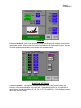
Verify that when the transmitter reads 0.00, the BCS 6000 touchscreen display also reads 0.00.
If necessary, adjust the transmitter 4 mA value using the following procedure.
•
•
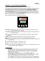
Press the NEXT button one time to change the lower display to CALIB.
Press ENTER to change the lower display to CAL AT0.
•
•
•
Press NEXT until the lower display reads ADJ 4MA.
Press ENTER and the lower display will read A 4MA ∧∧.
If the DPS display reads less than 0.00, increase the 4 mA calibrations as follows:
o Press NEXT to change the lower display to A 4MA ∧.
o Each press of the ENTER button will slightly increase the transmitter output and
the DPS display should increase until it reads 0.00.
If the DPS display reads greater than 0.00, decrease the 4 mA calibrations as follows:
∨
o Press NEXT to change the lower display to A 4MA .
•
Each press of the ENTER button will now slightly decrease the transmitter output
and the DPS display should decrease until it reads 0.00.
Press NEXT to step through the remaining calibration options until the lower display
reads SAVE.
Press ENTER to save the new zero calibration and exit the calibration mode. Note that
calibration changes can be discarded by pressing ENTER when the lower display reads
CANCEL instead of SAVE
o
•
•
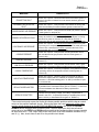
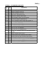
CONFIGURATION PARAMETERS
The transmitter has been factory configured and should not require any field modifications. The
following parameter settings are provided for reference only.
PARAMETER
LOWER DISPLAY
UPPER DISPLAY
External Zero (Not applicable)
EX ZERO
EXZ DIS
Output Direction
OUT DIR
FORWARD
Output Mode
OUTMODE
LINEAR
Output Failsafe
OUTFAIL
FAIL LO
Signal Dampening
DAMPING
NO DAMP
Display Engineering Units
DISP EGU
USE EGU
Select Engineering Units
EGU SEL
INH2O
Lower Range Value
EGU LRV
00.00
Upper Range Value
EGU URV
1.00, 3.00 or 5.00