1
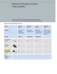
ebm-papst
EC communication
Hardware and software
for EC bus systems
The best connections for a flexible control system
The engineer’s choice
Communication on all channels
Fan networks made up of ebm-papst EC fans render their service in refrigeration and air-conditioning technology, in building
ventilation, clean rooms and many other application areas. For communication with the bus systems, the ebm-papst product
range provides various interfaces and software solutions that give you optimum support for setting up and monitoring networks.
Open and closed-loop control, programming, measuring
In addition to their outstanding energy efficiency, the intelligent features for
open and closed-loop control are among the chief advantages of ebm-papst
EC technology. From simply reading out the current speed to configuring
a sensor control, the integrated electronics of all EC fans offer numerous
options for optimally tuned and efficient operation of your system.
Depending on the planned use, application, work environment and existing
equipment, various solutions provide assured communication with your
ebm-papst EC fans. But which software is compatible with which bus system? Which interface converter connects which computer to which system?
On the following pages, we provide an overview of the combination options
of our visualisation software with the MODBUS RTU and ebmBUS bus systems as well as the various communication standards, including Bluetooth®
wireless technology.
GreenTech – economy and ecology going hand in hand
GreenTech follows a firmly held conviction: each newly developed product
Creed
must exceed the economic and ecological performance of its predecessor.
To this end, we are constantly improving materials and processes, flow
Development
behaviour and power – and reducing energy consumption. State-of-the-art
energy, air-conditioning and ventilation technology provides maximum
energy efficiency in our plant. Numerous environmental prizes, distinctions
and the groundbreaking energy levels, which fall below even the most
Application
stringent limits, are the reward for our efforts.
Production
GreenTech pays off for our customers, particularly due to the ebm-papst
EC (electronically commutated) technology. It is not only the heart and soul
of our philosophy, but also the core of our most efficient products. It attains
Awards
efficiency up to 90 %, provides maximum energy savings and makes the
products maintenance-free. With integrated open or closed-loop control
and bus compatibility, it is an environmentally sound and, in the long run,
more cost-effective alternative to AC technology.
2
The right protocol for every occasion
Regardless of whether a large number of nodes or broad scope of configuration options and mixed environments are in the
focus of EC communication: software, hardware and interface converters from ebm-papst provide smooth data transfer based
on ebmBus V3 and MODBUS RTU, two bus protocols that are particularly well suited for EC technology. For even more freedom
of choice in implementation, control programs such as Fan Control for PDAs and EC Control for PCs even support both standards.
RS485 ebmBUS – the specialist for a high number of nodes
RS485 MODBUS RTU – open standard with wide range of function
This bus protocol, developed by ebm-papst specifically for the require-
RS485 MODBUS RTU, which came into being back in 1979, has become
ments of EC technology, is perfectly designed for situations in which
established as a worldwide standard for controlling actuators and sensors,
a large number of fans with little need for individual configuration are
not least due to its open protocol. A great number of settings can be con-
to be controlled. Up to 7,905 slaves can communicate with one master
figured easily for up to 247 slaves. Each fan is assigned two parameter sets.
(PC/PDA). For this purpose, the Fan Control software program is avail-
They allow you to save different configurations, for example for summer
able for mobile terminal units and LISA 5 as well as EC Control for PC-
and winter time, day and night or standard and high-performance mode.
based platforms. RS485 ebmBUS, which has been continuously further
Three data sets per EC node also provide the ability to implement backup
developed and is now in its third generation, has proven to be a robust
functions. In combination with read/write authorisations, an extensive fault
communication protocol that is equally easy to implement and use.
memory and an emergency operation function, RS485 MODBUS RTU fea-
Clean rooms are a typical application area.
tures outstanding characteristics in terms of both operating convenience
and reliability. Typical application area in this case: refrigeration and airconditioning technology.
Decide at a glance what is most important to you
RS485 ebmBUS
RS485 MODBUS RTU
Baud rate
9,600
19,200
Parity
none
even
Number of nodes*
up to 7,905
up to 247
Profiles
–
•
Broadcast commands
•
–
Devices in the bus
only ebm-papst
ebm-papst and others
Configuration options
good
outstanding
Fault detection
XOR
CRC16
Fault memory
last 3
last 13
Software support
EC Control
LISA 5
Fan Control
Fan Clone
EC Control
Fan Control
Fan Clone
* On installations with more than 31 fans, RS485 repeaters have to be used, depending on the type of fan.
3
At a glance.
The right software for the compatible interface.
Using the matrix on this page, we show you which control software communicates with which of the two bus systems, and from
which input device. This allows you to understand the relationships at a glance. For direct comparison of the various strengths and
features, to the right is an overview of the most important functions of the control software programs. This allows you to quickly
and easily find out which combinations are best for your systems.
The perfect match: supported interfaces and protocols
Software
Hardware
EC Control
LISA 5
Fan Control
Fan Clone
EC controller
(page 6)
(page 7)
(page 8)
(page 9)
(page 18)
PC/laptop
PC/laptop
PDA/smartphone
PDA/smartphone
•
•
Bluetooth
adapter
(page 10)
RS232 – RS485
interface converter
with electrical
•
•
•
•
•
•
•
•
•
•
•
•
•
isolation
(page 12)
RS232 – RS485
interface converter
without electrical
isolation
(page 14)
Ethernet – RS485
interface converter
•
(page 16)
RS485 ebmBUS
•
RS485
•
MODBUS RTU
4
•
Performance features of the control software programs for PCs and PDAs
EC Control
LISA 5
Fan Control
Query and modify parameters of one fan
•
•
Modify parameters for group/entire system
–
(•)
–
Group view/floors
•
•
(•)
Detailed error history when software runs for long periods
•
•
–
Mapping a system layout/floor plan
•
•
–
Search for a fan with an unknown address
–
•
•
Setting parameters graphically
–
–
•
E-mail on error
•
•
–
Manageability
(•)
(•)
•
Support for multiple languages
•
•
•
Support for RS485 ebmBUS
•
•
•
Support for RS485 MODBUS RTU
•
–
•
Support of Ethernet and multiple subnets
•
–
–
Duty cycle display on fan symbol
•
–
–
Display of information below fan symbol
•
–
–
Display of the system in a tree structure
•
–
–
Support of multiple configurations in one installation
•
–
–
German and English user manual (PDF)
•
–
•
Timer
–
•
–
Integrated help system (English)
•
–
–
Key:
• = Performance feature present
(•) = Possible in part/to a limited extent
– = Not present
5
Special or universal?
Our high-performance control programs.
The ebm-papst EC Control and LISA 5 control programs enable detailed control and monitoring of fan
groups in ebmBUS or ebmBUS and MODBUS RTU networks. The multilingual and intuitively operated
interfaces in the familiar Windows® system environment provides you with easy and logical control.
For example, you can position fans on the floor plan of your storey in a simple and clearly arranged
manner. This lets you always keep tabs on your networks, even if they have many thousands of fans.
EC Control software for EC systems
EC Control enables visualisation and programming of ebmBUS and MODBUS
RTU fan networks and can be configured for both serial and Ethernet interface converters. The software supports the maximum number of devices
allowed by the respective bus system (up to 7,905 fans for ebmBUS and
247 for MODBUS RTU). For shorter latencies, multiple interface converters
can be connected.
Where necessary, the variable user interface of EC Control makes it easy to
distinguish between the various interface converters. It shows only the entries
that are relevant to the specific system. Additional features include support
of a second monitor, a tree-shaped management structure for finding individual fans in large systems efficiently and an online help.
System version: EC-Control 1.1
Functions
Item number: 25714-2-0199
– Configuring over 40 fan parameters such as operation mode, set values
Delivery scope:
and control parameters
CD-ROM with
– Changing fan addresses
– Software
– Reading out fan parameters such as actual speed, serial number and
– German and English manuals in PDF format
production date
– Reading out fault status and fault memory
– Quick video guide
Language: German, English
– Saving various configurations as an exportable and editable profile
– Monitoring installations, including the possibility of reporting failures
by e-mail
System requirements:
– Windows 2000 SP4 or higher, XP SP3 or higher, Vista SP1 or higher
– Administration of multiple systems within one program installation
– 30 MB of free hard drive space
– Support for RS232/RS485 and Ethernet/RS485 interface converters
– 512 MB RAM; for Vista, at least 1 GB RAM recommended
– Simultaneous monitoring of ebmBUS and MODBUS RTU-based system
– CPU Pentium III or higher, 800 MHz or comparable; for simultaneously
components (requires several interface converters)
operation with multiple interface converters, a faster CPU is recommended
– Monitor with at least 1024 x 768 pixel resolution and 16-bit colour depth
– CD-ROM drive (for installation only)
– At least one interface converter of the following types:
• RS232 (article No. 21487-1-0174) with electrical isolation
• RS232 (article No. 21495-2-0174)
• Ethernet (article No. 21488-1-0174)
• Ethernet (UL certified) (article No. 21489-1-0174)
6
LISA 5 control software for EC systems
LISA 5 is the control software specially developed for ebmBUS. It is compatible with all EC motors and electronics that are networked via ebmBUS.
The group-oriented arrangement of the fans enables individual control and
monitoring of a maximum of 7,905 fans in up to 255 groups on 10 floors.
Using broadcast commands, individual groups or all fans can be triggered
simultaneously.
Functions
– Individual control and monitoring of max. 7,905 fans,
including the ability to report failures by e-mail
– Group-oriented arrangement of the fans
– Level 1: Overview display for up to 10 floors
– Level 2: Overview display for up to 255 groups within a floor
System version: LISA 5.1
– Level 3: Overview display for 31 fans within a group
Item number: 25711-2-0199
– Broadcast command for one group or all fans
Delivery scope:
– Speed, temperature or pressure control
CD-ROM with software
– Error message
Languages: German, English, Spanish, French, Italian, Dutch, Finnish,
Japanese, Chinese (simplified), Chinese (traditional), Russian
– Fan status display
– Programming individual fans, e. g. changing the fan’s address
System requirements:
– Changing the control mode of the fan
– Windows 2000, XP
(speed control/PWM control/sensor control)
– 21 MB of free hard drive space
– Changing set values (speed, direction of rotation etc.)
– 128 MB RAM
– Configuring control parameters
– CPU Pentium 200 MHz or higher (or comparable)
– Changing minimum/maximum values
– Monitor with at least 800 x 600 pixel resolution and 8-bit colour depth
– CD-ROM drive (for installation only)
– Read-out of fault status
– Identification of a fan with unknown fan address
– Configuring the sensor characteristics for sensor control
– Configuring the start-up and run-down ramp (“soft start”)
– RS232 interface (for laptops, a PC card can also be used, but not a
USB-RS232 adapter)
– At least one interface converter of the following types:
• RS232 (article No. 21487-1-0174) with electrical isolation
• RS232 (article No. 21495-2-0174)
7
Communication without cable clutter.
The control software programs for Pocket PCs.
The Fan Control mobile software and its sister product, Fan Clone, are intuitive tools for wireless
communication with ebmBUS and MODBUS RTU-compatible fan networks. Fan Control serves as a
diagnostics and configuration tool for visualisation, monitoring and programming of fans. For this
purpose, Fan Clone enables simplified commissioning of systems that consist of multiple identically
configured fans. All configuration tasks and reading out and cloning fan configurations take place
easily and conveniently via Bluetooth wireless technology.
Fan Control software for Pocket PC/PDA
Fan Control is compatible with both ebmBUS and MODBUS RTU devices. The
software has graphical and numerical configuration options, allows you to
save data records and two parameter sets, e. g. for daytime and nighttime
operation. Using an emergency operation function, you can define a set
value that the fan defaults to automatically if no bus communication takes
place for a configurable time period.
Functions
– Monitoring of fan groups
– Fan status display
– Programming individual fans, e. g. changing the fan’s address
– Changing the control mode of the fan (speed control/PWM control/sensor control)
System version: Fan Control 3.1
Item number: 25713-2-0199
– Changing set values (speed, direction of rotation etc.)
Delivery scope:
– Setting closed-loop control parameters (graphically, too)
CD-ROM with
– Changing minimum/maximum values
– German and English manuals in PDF format
– Graphical configuration of minimum and maximum PWM as well as
– Installation program (for every language)
set value, for sensor control (pure P-controller), also the control range
– Video setup guide for the Bluetooth connection
Languages: German, English, Spanish, French, Italian, Dutch, Finnish,
– Read-out of fault status
Japanese, Chinese (simplified), Chinese (traditional), Russian
– Identification of a fan with unknown fan address
– Search for unknown device addresses
System requirements:
– Configuring the sensor characteristics for sensor control
– ebm-papst Bluetooth Adapter (article No. 21501-1-0174),
– Configuring the start-up and run-down ramp (“soft start”)
– MODBUS RTU: graphical configuration of the curve of the 0–10 V
analogue input, 10 V = off and 1 V = maximum duty cycle are thus
no longer a problem!
alternative: RS232 interface converter with cable
(article No. 21487-1-0174)
– Pocket PC/PDA or smartphone with resolution of at least
240 x 230 pixels
– MODBUS RTU: reset the fan to the factory settings
– Windows Mobile 5 for Pocket PC or
– Read out a wide variety of fan parameters
– Windows Mobile 5 Phone Edition or
– Windows Mobile 6 Classic or
– Windows Mobile 6/6.1 Premium
An always up-to-date list of compatible devices is available at
www.ebmpapst.com/downloads
8
Fan Clone commissioning software for Pocket PC/PDA
Fan Clone allows you to efficiently program configuration variants produced
in small lots. After the configuration of one fan is read out and stored, the
read-out or stored configuration is transferred to other fans, with or without changing the device address of the target fan. Fan Clone also identifies
fans with an unknown fan address.
Functions
The following parameters can be copied onto other fans using this software:
– Operating mode (closed-loop speed control/sensor control/PWM control)
– Save set value to EEPROM
– Source of set values (BUS vs. analogue input)
System version: Fan Clone 2.0
– Control function (heating/cooling)
Item number: 25715-2-0199
– Default set value
Delivery scope:
– P-, I-, D**-factor
CD-ROM with
– Maximal speed
– English manual in PDF format
– Min./max. PWM
– Installation program
– Start PWM
– Video setup guide for the Bluetooth connection
– Set value 0 and 1 (active with digital interpretation of analogue input)**
Language: English
– Reduction factor**
– Sensor minimum/maximum value
System requirements:
– Sensor unit
– ebm-papst Bluetooth Adapter (article No. 21501-1-0174),
– Run-up and run-down time
alternative: RS232 interface converter with cable
– Sampling interval of current regulator
(article No. 21487-1-0174)
– Source for control function, bus vs. external terminal (switch)*
– Output function of analogue output*
– Pocket PC/PDA or smartphone with minimum resolution
of 240 x 230 pixels and Bluetooth interface
– Output curve of analogue output*
– Windows Mobile 5 for Pocket PC or
– Emergency operation function*
– Windows Mobile 5 Phone Edition or
– Windows Mobile 6 Classic or
** MODBUS RTU
– Windows Mobile 6 Pentium – 6/6.1
** ebmBUS
An always up-to-date list of compatible devices is available at
www.ebmpapst.com/downloads
9
Bluetooth interface adapter
RS485
For wireless programming and monitoring, ebm-papst fans equipped with an RS485 interface
can communicate with Pocket PCs/PDAs or smartphones via the ebm-papst Bluetooth Adapter.
Diagnostics in the event of fault are likewise possible. To do so, the Bluetooth Adapter creates a
bi-directional connection from RS485 units to Bluetooth-compatible PDAs or smartphones.
Nominal data
Type
21501-1-0174
Power supply
Current draw
Transmitting power
Range (depending on ambient conditions)
Dimensions
VDC reversible
mA
mW
m
mm
15–24
30
1
10–20
100 x 50 x 25
Operating mode
RS485, two-wire mode without echo, automatic switchover between send and receive
RS485 connection
Molex Minifit socket (compatible plug: Molex, article No. 43025-0400 and 43030-0001)
Frequency band
ISM band (2402–2480 MHz)
Status display
Via LED
– Green: power supply OK
– Yellow (flashing): Bluetooth connection active
– Red (top, left of green LED): data transmission from PDA/smartphone to fan
– Red (bottom, left of yellow LED): data transmission from fan to PDA/smartphone
Housing
Plastic housing
Type of protection
IP 20
Delivery scope
– Bluetooth Adapter and 4-conductor connecting cable with corresponding Molex plug and core-end sleeves
– Product description
10
Connecting the Bluetooth Adapter – example of a fan with MODBUS RTU compatibility
The Bluetooth Adapter is connected directly to the fan. The fan voltage of 15 or 20 V is used for the power supply of the adapter
so that no external power supply is required.
Note: Reversing the voltage does not present any problems for the Bluetooth Adapter, even if the fan displays an error regarding this.
The Bluetooth Adapter works in the same licence-free 2.4 GHz frequency band in which Wireless LAN networks operate.
The frequency hopping method used here provides immunity to interference.
Note: Only one Bluetooth Adapter is needed for communication with a system, no matter what its size.
1
External sensor
Pressure sensor,
temperature sensor
Power supply
Fans
Power supply
Bluetooth Adapter
MODBUS RTU RSA/RSB
PDA/Smartphone
ebm-papst Bluetooth Adapter
Art. No. 21501-1-0174
L3
KL1
L2
PE
L1
Aout
Din1
NC
Ain2 I
Ain1 I
NO
+20V
+10V
COM
GND
Ain2 U
GND
Din3
RSB
Ain1 U
Din2
KL2
RSA
KL3
PE
1 Example terminal assignment for fan
11
Interface converter
RS232 – RS485 with electrical isolation
This interface converter permits bi-directional connection of RS232 devices (laptop or PDA) with
bus-compatible devices (electronic commutation units with RS485 interface). The interface features
electrical isolation between the RS232 and RS485 sides.
Nominal data
Type
21487-1-0174
Nominal voltage and plug-in supply unit
Power supply
Current draw at no-load operation
Dimensions
VAC
VAC/VDC
mA
mm
230
12–14
150
105 x 75 x 22
Operating mode
RS485, two-wire mode with echo and automatic control
Safety
Electrical isolation between RS232 and RS485
Electrical isolation
Min. 1kV isolation voltage between RS232 and RS485 interfaces and between power supply and interfaces
ESD immunity
Up to 15 kV (acc. to IEC 801-2, Stage 4)
RS232 connection
9-pole SUB-D plug with PC-COM assignment
RS485 connection
9-pole SUB-D plug
Terminating resistor
built-in, activated via switch
Status display
Via LEDs
– Green: supply voltage OK
– Red: data transfer
Housing
Plastic housing
Installation
Standard rail mounting in accordance with DIN EN 50022-35
Delivery scope
– Interface converter
– Plug-in supply unit (230 VAC/12 VDC, 500 mA)
– Adapter lead to the computer with 2 x 9-pole SUB-D sockets
– Adapter lead to the fan with 9-pole SUB-D socket and RS485 screw terminal
– Product description and manual (German and English)
12
Connecting the interface converter – example of a fan with MODBUS RTU compatibility
In conjunction with the EC Control or LISA 5 programs, connections for bus-compatible fans can be implemented easily using a computer or laptop.
No special setup of the interface converter is required.
Note: Because of the electrical isolation, use in even large networks with potential differences is possible without any problems.
Note for large systems: After 31 fans, a repeater can be installed in order to connect another 31 fans.
1
External sensor
Pressure sensor,
temperature sensor
Laptop
Power supply
Fans
MODBUS RTU RSA/RSB
RS232
Interface converter
Art. No. 21487-1-0174
Power supply
plug unit
Interface converter
2
KL1
L1
L3
PE
L2
Aout
Din1
NC
Ain2 I
Ain1 I
NO
+20V
+10V
COM
GND
Ain2 U
GND
Din3
RSB
Ain1 U
Din2
KL2
RSA
KL3
2 Interface converter connection
PE
1 Example terminal assignment for fan
A
B
A = RSA
B = RSB
13
Interface converter
RS232 – RS485
This interface converter permits bi-directional connection of RS232 devices (laptop or PDA) with
bus-compatible devices (electronic commutation units with RS485 interface). The power supply is
from the RS232 output of the laptop or PDA.
Nominal data
Type
21495-2-0174
Dimensions
Power supply
*Otherwise via RS232 DTR, TxD and RTS signal
mm
VDC
Operating mode
RS485, 2-wire mode with echo and automatic control
Status display
Via LEDs
– PWR: Power supply
– TXD: Data transfer (send)
– RXD: Data transfer (receive)
Housing
Plastic housing
Terminal
Screw terminal, TRX+ = RSA, TRX– = RSB
Terminating resistor
Built-in, activated via switch
Delivery scope
– Interface converter
– English-language operating manual
14
73 x 37 x 19
7–12*
Connecting the interface converter – example of a fan with MODBUS RTU compatibility
The combination with the EC Control and LISA 5 programs enables cost-effective programming and monitoring of bus-compatible EC fans.
The interface converter can be connected directly and used without any special setup.
Note: The interface converter does not have any electrical isolation and thus is suitable for battery-operated devices only.
The switch (on top of the interface converter) must be set to RS485.
1
External sensor
Pressure sensor,
temperature sensor
Laptop
Power supply
Fans
MODBUS RTU RSA/RSB
Interface converter
Art. No. 21495-2-0174
2
1 Example terminal assignment for fan
KL1
Aout
TRX–
GND
RX+
RX–
L3
L1
L2
PE
NC
NO
COM
Ain2 I
PE
TRX+
Din1
Ain1 I
+20V
+10V
Ain2 U
GND
GND
Ain1 U
Din3
KL2
RSB
RSA
Din2
KL3
2 Interface converter connection
15
Ethernet interface converter
RS485
This interface converter permits bi-directional connection of RS485 units and Ethernet-compatible
computers or laptops using the EC Control software (article No. 25714-2-0199)
Nominal data
Type
Nominal voltage and plug-in supply unit
Power supply
Current draw
Frequency
Ambient temperature (arranged in series)
Ambient temperature (not arranged in series)
Dimensions
VAC
VDC
mA
Hz
°C
°C
mm
21488-1-0174
21489-1-0174 (UL version)
100–240
12–48
85
50/60
0 to +50
0 to +60
105 x 75 x 22
100–240
12–48
85
50/60
0 to +50
0 to +60
105 x 75 x 22
Operating mode
RS485, two-wire mode without echo, automatic switchover between send and receive
Safety
Electrical isolation between Ethernet and RS485
Electrical isolation
min. 500 V
Ethernet connection
8-pole RJ45 socket
10/100 Mbps autosensing
RS485 connection
9-pole SUB-D plug, depending on configuration:
– 9,600 baud, 8 data bits, 1 stop bit, no parity (ebmBUS) or
– 19,200 baud, 8 data bits, 1 stop bit, even parity (MODBUS RTU)
Protocols used
– TCP
– Telnet
Status display
Via LEDs
– Green (left): power supply
– Green (right): data communication
– Red: fault
Housing
Plastic housing
Type of protection
IP 10
Installation
Standard rail mounting in accordance with DIN EN 50022-35
Delivery scope
– Interface converter
– Plug-in supply unit
– RS485 cable, D-Sub to screw terminal
– Network cable (crossover, Cat 5)
– German and English product description
16
Connecting the interface converter (Ethernet) – example of a fan with MODBUS RTU compatibility
The Ethernet interface converter serves to integrate bus-compatible EC fans into existing computer networks. This increases the spatial independence
of the control room and fans. Other than a power supply, all that is needed is a static IP address, which can be assigned easily using the EC Control
software. Multiple Ethernet interface converters can be used without any problems. This allows, for example, larger systems to be divided up spatially
to reduce latencies.
Note for large systems: After 31 fans, a repeater can be installed in order to connect another 31 fans.
1
External sensor
Pressure sensor,
temperature sensor
Laptop
Power supply
Fans
MODBUS RTU RSA/RSB
Ethernet/TCP/IP
Interface converter
Ethernet
Art. No. 21488-1-0174
Art. No. 21489-1-0174
2
KL1
L1
L3
PE
L2
Aout
Din1
NC
Ain2 I
Ain1 I
NO
+20V
+10V
COM
GND
Ain2 U
GND
Din3
RSB
Ain1 U
Din2
KL2
RSA
KL3
2 Interface converter connection
PE
1 Example terminal assignment for fan
A
B
A = RSA
B = RSB
17
EC controller
Stand-alone control device for refrigeration and air-conditioning technology in conjunction with the
corresponding sensors. Using the controlled 0–10 V output or RS485 MODBUS RTU connection,
ebm-papst fans with a corresponding input can be triggered. The function includes multifunctional
pressure and temperature control as well as display and entry of various parameters. The integrated
LCD display provides easy operation across multiple levels.
Nominal data
Type
CCC000-AD06-02
Nominal voltage
Frequency
Power consumption
Power supply for sensor
Output current
Permitted ambient temperature
Permitted storage temperature
Dimensions
Specifications subject to change!
V
Hz
W
VDC
mA
°C
°C
mm
1~200–480
50/60
15
24
120
0 to +60
–20 to +60
200 x 167 x 76
Inputs/outputs
– 24 V power supply for sensors
– Analogue inputs for connecting up to 2 sensors per type
– 4 digital inputs
– 2 programmable relay outputs, 2 voltage outputs 0–10 V
– RS485 MODBUS RTU
Applications
– Temperature control, standard
– Pressure control of ventilation systems, condensers, 2-circuit condensers
– Pressure control, ambient temperature-compensated
These applications are the factory defaults. Other applications can be programmed individually.
Sensors
– Temperature sensor KTY 10-6 (R25 = 2 kΩ), NTC 103AT (R25 = 10 kΩ)
– Pressure sensor 0 to 100/200/500/1000 Pa (0–10 V output), 0 to 30 bar (4–20 mA output)
– ebm-papst temperature sensors, Art. No. 50003-1-0174 and 50005-1-0174
– Other sensors can be programmed individually
Menu languages
German/Swedish/Danish/English (factory setting)
Housing
Plastic housing
Product conforming
to standard
CE
Type of protection
IP 54 (acc. to DIN EN 60529)
EMC
Acc. to EN 61000-6-3 and EN 61000-6-2
Installation
Vertical wall mounting, direct solar radiation and installation on vibrating substrate is not permitted.
Electrical leads via terminal strips
18
Connecting the EC controller – example of a fan with MODBUS RTU compatibility
The EC controller functions as a stand-alone control device for fan networks in combination with external sensors. Factory default applications ensure
easy commissioning – connecting a computer or other software-supported devices is not necessary. For programming new applications and for
monitoring, an integrated keypad control with LCD display replaces the external input devices.
Note for large systems: After 31 fans, a repeater can be installed in order to connect another 31 fans.
1
External sensor
Pressure sensor,
temperature sensor
RS485 MODBUS RTU
or 0 –10 V
Power supply
2
EC controller
2 Example terminal assignment – EC controller
RSA
GND
Temp
RSB
GND
D4
RSA
GND
RSB
D3
GND
Temp
D1
D2
GND
0–10 V E
GND
GND
0–10 V E
GND
GND
GND
0–10 V E
0–20 mA
+24 V
0–10 V E
GND
GND
Temp
0–20 mA
Relais 2
Temp
Relais 1
Relais 2
KL3
+24 V
L1
3
Relais 1
L1
KL2
L3
KL1
L2
PE
PE
Aout
Din1
NC
Ain2 I
Ain1 I
NO
+20V
+10V
COM
GND
Ain2 U
GND
Ain1 U
Din2
Din3
RSA
KL2
RSB
KL3
N/L2
KL1
1 2
PE
1 Example terminal assignment for fan
19
37818-7-8811 wob 09/09 2'
In this brochure, we hope to give you a comprehensive overview of how the hardware and software of
our EC communication products interact. If you have any other questions about a specific application,
please do not hesitate to contact us. Our specialists will be happy to help.
ebm-papst
Mulfingen GmbH & Co. KG
Bachmühle 2
D-74673 Mulfingen
Phone +49 7938 81-0
Fax +49 7938 81-110
[email protected]
www.ebmpapst.com