1
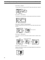
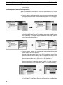
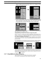
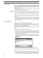
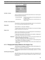
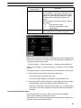
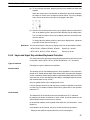
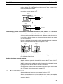
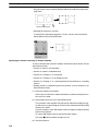
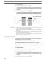
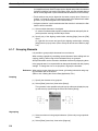
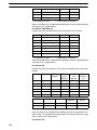
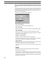
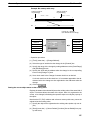
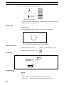
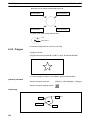
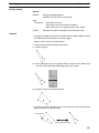
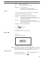
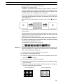
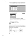
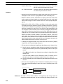
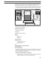
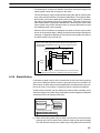
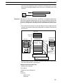
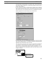
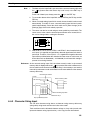
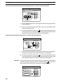
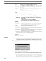
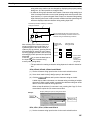
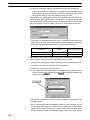
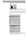
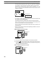
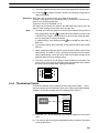
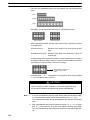
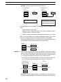
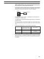
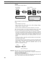
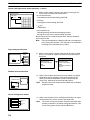
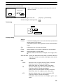
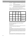
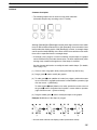
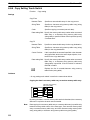
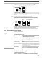
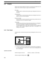
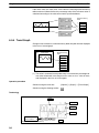
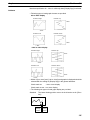
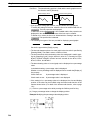
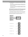
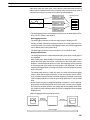
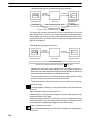
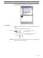
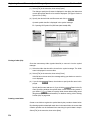
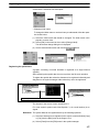
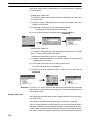
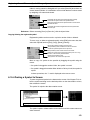
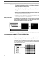
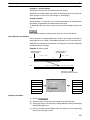
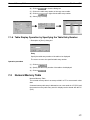
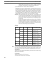
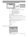
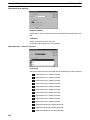
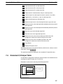
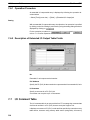
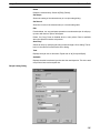
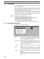
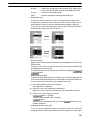
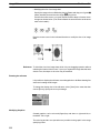
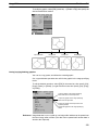
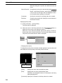
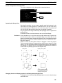
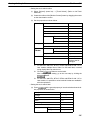
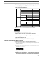
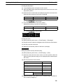
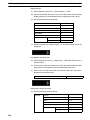
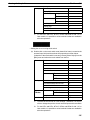
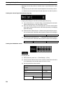
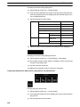
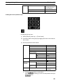
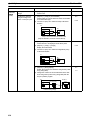
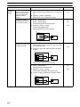
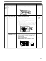
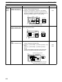
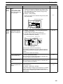
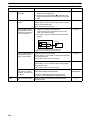
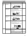
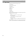
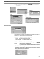
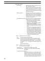
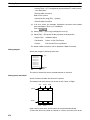
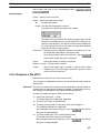
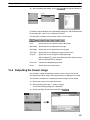
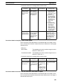
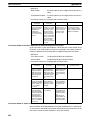
Touch Switches
Section
6-8
Guidance
Common description
The following shapes can be used for touch switch elements.
(Selectable shapes vary according to the PT model.)
Standard
Circle
Shadow
Polygon
3-Dimension
Rectangle
Sector
Although [Standard] and [Rectangle] have the same shape, how the touch switch
frame is defined differs between them. With [Standard], the touch switch frame
itself provides the display graphic. With [Rectangle], however, a rectangle shape
can be specified independently of the touch switch frame and the touch switch
frame can be separated from the rectangle shape.
If rectangle, circle, polygon, or sector is selected, only the shape of a graphic
can be modified in the procedure shown below. The touch switch frame (touch
sensing area) remains unchanged even if the shape is modified.
Use the element edit function to modify the touch switch shape. (For details,
refer to page 112.)
(1) Click on a line of a graphic while pressing the Shift key and Ctrl key.
(2) Drag a green mark to modify the graphic.
(3) To add a green mark (addition of a node) in a polygon, position the mouse
cursor on the line in a graphic and execute a vertex addition operation (right
click the mouse → [Add Node]).
To delete a green mark (deletion of a node), position the mouse cursor on
the green mark to be deleted and execute a vertex deletion operation
(right click the mouse → [Remove Node]).
(4) Drag the added green mark to modify the shape of the graphic.
Example: Modification of the shape of polygon
(1)
(2)
(3)
(4)
A touch switch element can display a label (touch switch name).
215