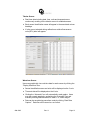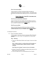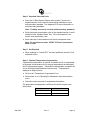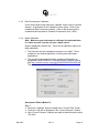
1
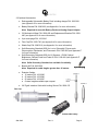
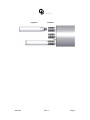
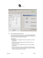
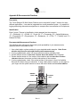
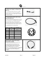
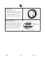
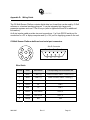
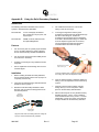
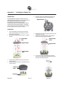
User’s Manual April 23, 2012 P/N: 998-2205 Revision K TURNER DESIGNS 845 W. Maude Ave. Sunnyvale, CA 94085 Phone: (408) 749-0994 FAX: (408) 749-0998 Table of Contents 1. Introduction 1.1 Introduction 1.2 Important Note Regarding the Use of the Fluorescein Sensor 2. Inspection and Setup 2.1 Instrument Checklist 2.2 Optional Accessories 2.3 Installing the Cyclops-7 Sensors 3. C-Soft Windows™ User Interface 3.1 Software Installation and PC Requirements 3.1.1 Minimum PC Requirements 3.1.2 Software Installation 3.1.3 Integration / Interface Adapter Cable Installation 3.1.4 PC Software Interface 3.2 Software Operation 3.2.1 Settings Screen 3.2.2 Current Data and Calibration Screens 3.3 Calibration Procedures 3.3.1 Direct Concentration Calibration 3.3.2 Raw Fluorescence Calibration – Blank Subtracted 3.3.3 Raw Fluorescence Calibration 3.3.4 Depth Calibration 3.4 Log Setup Screen 3.5 Enabling Data Output Ready State 3.6 Downloading and File Management 4. Maintenance and Warranty 4.1 Maintenance 4.1.1 Rinsing 4.1.2 Care for the Bulkhead Connector 4.1.3 Care for the Sensor Ports 4.2 Terms 4.3 Warranty Service 4.4 Out of Warranty Service Appendices A Specifications B Recommended Practices C Cable Guide D Wiring Guide E Using the Solid Secondary Standard F Linear Range, Quenching and Temperature Considerations G Installing the Mechanical Wiper H Installing the Flow Cap I Installing the Shade Cap J Installing the Battery Bracket and Battery K Charging the Submersible Battery Pack L How to Set up Hyperterminal for Digital (ASCII) Data Capture M Integrator Firmware N Campbell Scientific Datalogger Integration O Optical Specification Guide 4 4 5 6 7 9 9 9 9 10 11 11 12 15 15 17 18 18 19 21 21 23 23 23 23 23 24 24 28 29 30 31 32 34 35 36 38 40 41 42 44 45 46 WASTE ELECTRICAL AND ELECTRONIC EQUIPMENT (WEEE) DIRECTIVE Turner Designs is in the business of designing and selling products that benefit the well-being of our environment. Accordingly, we are concerned with preserving the surroundings wherever our instruments are used and happy to work with customers by complying with the WEEE Directive to reduce the environmental impact resulting from the use of our products. WEEE Return Process: To arrange the return of an end-of-life product, proceed as follows: If you purchased your instrument through a Turner Designs Distributor please contact your local representative. They will instruct you where to return the endof-life product. If you purchased your instrument directly from Turner Designs please contact Turner Designs Customer Service By Phone: 1-408-212-4041 or Toll Free: (877) 316.8049 By Email: Customer Service at [email protected] Turner Designs will provide a WEEE RMA Number, a Shipping Account Number, and a Ship to Address. Package and ship the product back to Turner Designs. The product will be dealt with per Turner Designs’ end-of-life recycling program in an environmentally friendly way. 1. Introduction 1.1 The C6 Multi-Sensor Platform was designed to integrate up to six Cyclops-7® submersible sensors for extended or short-term deployments. The C6 MultiSensor Platform provides automatic gain control, calibration, data logging and digital data output for each Cyclops-7 sensor. The C6 Multi-Sensor Platform comes with factory-installed temperature and pressure sensors and is rated to a depth of 600 meters. The C-Soft Windows based user interface allows for intuitive calibration, data logging set up and file downloading. Existing Cyclops7 users can easily integrate their sensors into the C6 Multi-Sensor Platform. 1.2 Important Note Regarding Use of Fluorescein Sensor For C7’s manufactured prior to 2/15/2011, the Fluorescein sensor should not be enabled for simultaneous data collection with Chlorophyll and Rhodamine sensors or it will produce unreliable results. For C7’s manufactured after 2/15/2011 this interference was designed out. If you would like to send your C7 back to Turner Designs to resolve this, please contact [email protected]. 998-2205 Rev. K Page 4 2. Inspection and Setup 2.1 Instrument Checklist The C6 Multi-Sensor Platform package (P/N: 2200-000) includes: ♦ C6 Multi-Sensor Platform ♦ Factory-installed pressure sensor ♦ Factory-installed temperature sensor ♦ Computer Interface cable with 12V power supply ♦ Integration / Interface Adapter Cable (see Appendix M and N for more information about integration) ♦ Sensor fasteners ♦ 8-pin female plug ♦ CD including C-Soft software, user’s manual, cable guide and quick start guide Sensor fastener Temperature sensor Eyelift holes 8-pin female end plug Pressure sensor 12V Power Supply Integration / Interface Adapter Cable Computer Interface Cable 998-2205 Rev. K Page 5 2.2 Optional Accessories: ♦ Rechargeable Submersible Battery Pack including charger P/N: 2200-601 (see Appendix K for more information) ♦ Battery Bracket P/N: 2200-603 (see Appendix J for more information) Note: Required for use with Battery Pack and Analog Output Adaptor. ♦ C6 Mechanical Wiper P/N: 2200-450 and Replacement Brushes P/N: 2200460 (see Appendix G for more information) ♦ 6-pin male plugs P/N: 105-2210 ♦ Flow Cap P/N: 2200-700 (see Appendix H for more information) ♦ Shade Cap P/N: 2200-510 (see Appendix I for more information) ♦ Solid Secondary Standard (SSS) for in vivo Chlorophyll, Phycocyanin, Phycoerythrin, Rhodamine, and Fluorescein P/N: 2100-900 (see Appendix E for more information) ♦ Solid Secondary Standard (SSS) for UV Sensors - CDOM, Optical Brighteners, Refined Fuels and Crude Oil P/N: 2100-904 (see Appendix E for more information) Note: Solid Secondary Standard not available for turbidity. ♦ Booster Kit P/N: 2200-900 Note: Required for cable lengths greater than 10 meters. 6-pin male plug ♦ Extender Cables: ♦ 10 meters P/N: 105-2595 ♦ 25 meters P/N: 105-2596 ♦ 50 meters P/N: 105-2597 ♦ Custom lengths available upon request ♦ 24” Pigtail Interface Cable with Locking Sleeve P/N: 2200-170 Flow Cap Submersible battery 998-2205 Rev. K Page 6 Shade Cap Mechanical wiper Battery bracket 2.3 Installing Cyclops-7 Sensors Up to six Turner Designs Cyclops-7 sensors can be installed onto the C6 MultiSensor Platform. The center port is intended for the optional mechanical wiper only. Follow the instructions below to successfully integrate your Cyclops-7 sensor. 1. Place the fastener on one of the Cyclops-7 ports of the C6 Multi-Sensor Platform and rotate to tighten. Make sure not to over tighten. 2. Align the 6-pin male end of the Cyclops-7 sensor with the C6 Multi-Sensor Platform port and fastener and press in the sensor. 3. Hold the Cyclops-7 in place and rotate the remaining ring on the fastener to tighten. This will lock the Cyclops-7 into position. 4. Follow the same installation instructions for the remaining Cyclops-7 sensors. 5. Install a 6-pin male plug onto any unused port on the C6 Multi-Sensor Platform. 998-2205 Rev. K Page 7 Cyclops-7 998-2205 Fastener Rev. K Page 8 3. C-Soft Windows™ User Interface The C-Soft Windows based user interface allows for intuitive calibration, data logging set up, and download functions. 3.1 Software Installation and PC Requirements 3.1.1 Minimum PC Requirements ♦ 133MHz microprocessor ♦ 600 X 800 VGA resolution ♦ Microsoft Windows 98 ♦ 32 MB RAM 3.1.2 Software Installation 1. Exit all Windows programs 2. Insert the C-Soft CD (also located on the Turner Designs Software / Firmware webpage under Customer Care). 3. Open the C-Soft software folder and double click on the setup icon. 4. The software will automatically be installed in the PC’s (C:/Program Files/C6) folder unless user selects alternate location. 5. After restarting the “C-Soft" icon is located on the desktop. Note: You may receive a warning message asking if you want to unblock messages, select "Unblock" 3.1.3 Integration / Interface Adapter Cable Installation 1. Insert the C6 software CD and install the Adapter Cable driver (Integration-Interface_Adapter_Drivers.exe) onto your PC. 2. Make sure nothing is plugged into the Adapter Cable’s connectors. 3. Plug the USB connector into a USB port on your computer and wait for hardware to automatically install. 4. Once USB is installed and ready to use, right click the My Computer Icon. Note: For Windows Vista or 7 users, open the start menu and right click on Computer. 5. Left click “properties” to open the properties window. 998-2205 Rev. K Page 9 6. If running Windows XP or older versions of Windows, click on the “Hardware” tab and then click “Device Manager” to open the list of devices installed on your computer. Note: For Windows Vista or 7 users, the Device Manager link is located in the upper left part of the properties window; you will not see a Hardware tab. 7. Scroll down and open the “Ports” heading from the list. 8. The newly installed Adapter will be titled “USB Serial Port” followed by a COM port designation in parentheses (for example, “(COM 5)”). 9. If the USB Serial Port’s COM designation is labeled as any number from 1-6, your installation is complete. Close all windows and make sure to set C-Soft to that specified COM designation when trying to connect via USB Adapter Cable connection. 10. If the USB Serial Port’s COM designation is greater than 6, right click on the “USB Serial Port” and click “properties” which will open up the properties menu. From that menu click on the “Port Setting” tab and then click “Advanced” which will open the advanced settings menu for that USB Serial Port. Choose any COM port 1-6 from the COM port pull-down menu and click “OK”. Note: Ideally you want to start with any port that is not in use; if all are in use then choose any port 1-6. Click “OK” to the warning box if it appears and Click “OK” to close any other open menus. Your installation is complete. Make sure to set C-Soft to that specified COM designation when trying to connect via USB Adapter Cable connection. 3.1.4 PC Software Interface Note: It is important that the steps be followed IN ORDER. Any variance from the procedure may result in the connection NOT being established. 1. Plug either the USB or serial connector of the adapter cable into your computer. Note: Either connection can be used for communicating and configuring the instrument. 2. Plug the interface cable onto the 8-pin bulkhead connector of the instrument. 3. Plug the interface cable’s serial plug into the adapter cable’s male serial plug. 4. Begin C-Soft by double-clicking on the C-Soft icon and choose the appropriate COM port from the pull down COM menu. 5. Plug the 12V power supply into a power source. 6. Wait for initialization process to complete. 998-2205 Rev. K Page 10 7. The connection icon, located on the upper right of the screen, will turn green if connected. Note: If the connection icon does not turn green disconnect and reconnect power. 3.2 Software Operation 3.2.1 Settings Screen The Settings Screen allows users to set the time and date, identify each Cyclops-7, update serial numbers and select sensors to be enabled. ♦ Users can manually set the date and time or choose to synchronize the C6 Multi-Sensor Platform to the PC date and time. ♦ Each channel (1-6) in the Settings Screen has a port associated with it on the C6 Multi-Sensor Platform that is numerically labeled (1-6) respectively. ♦ Click on the box adjacent to the channel to enable channel operation. If there is no sensor installed users will be unable to select that channel. ♦ Channels can be renamed using the dropdown selections or by manually entering a name. ♦ Channels can also be named using Cyclops-7 serial numbers. ♦ Settings will automatically be saved after exiting the Settings screen. 998-2205 Rev. K Page 11 3.2.2 Current Data and Calibration Screen The Current Data Screen allows users to view real-time data acquisition, in both tabular and waveform formats as well as conduct calibrations for each channel, and view calibration information. Current Data 998-2205 ♦ Sensor labels are displayed but cannot be changed in the Current Data screen. ♦ Real-time values are displayed next to each channel and in the adjacent Data Table. ♦ A calibration button is available for all Cyclops-7 sensors and the depth sensor. ♦ Real-time data can be saved by selecting the “Start Data Capture” button. Users will be prompted to enter a file name and file location. Data files will be saved in (*.csv) format. Rev. K Page 12 Tabular Screen ♦ Real-time data including date, time, units and temperature are continuously scrolling on the tabular screen for enabled sensors. ♦ Each sensor identification name will appear in the associated column headings. ♦ If units are not selected during calibration a relative fluorescence units (RFU) label will appear. Waveform Screen Users can graphically view real-time data for each sensor by clicking the “Display Waveform” box. ♦ Sensor identification name and units will be displayed on the Y-axis. ♦ Time and date will be displayed on the X-axis. ♦ Clicking the “Autoscale” box will automatically scale graphs. Users may also rescale graphs by unchecking the “Autoscale” box and manually entering desired values for either Y or X axis ranges. ♦ Data can be saved during waveform mode by clicking “Start Data Capture”. Data files will be saved as .csv format. 998-2205 Rev. K Page 13 Calibration Screen Users can calibrate Cyclops-7 sensors in either the direct concentration mode, raw fluorescence mode, or blank subtracted raw fluorescence mode. 998-2205 Rev. K Page 14 Direct Concentration Mode Values reported in the Direct Concentration Mode are scaled to a predetermined standard value and blank subtracted. The equation used to calculate concentrations after calibrating to Direct Concentration Mode is: Standard Value (units) x Sample RFU = Concentration (units) Standard RFU Raw Fluorescence Mode Blank Subtracted Values in the Raw Fluorescence Blank Subtracted Mode are noted as RFUB. It is important to note that these values are blank subtracted but are not scaled to a standard, they are relative values. Raw Fluorescence Mode Values in the Raw Fluorescence Mode are referred to as “Relative Fluorescence Units” (RFU). It is important to note that these values are not blank subtracted or scaled to a standard, they are relative values. 3.3 Calibration Procedures 3.3.1 Direct Concentration Calibration Following steps 1-5 will ensure values are reported as Blank Subtracted Concentrations in units of choice. See Appendix B for recommended practices. Step 1: Blanking ♦ Place the C6 Multi-Sensor Platform and Cyclops-7 sensors in a blank solution. Note: A blank solution is a solution without the fluorophore of interest (i.e. deionized water, artificial seawater, or filtered seawater) Note: Ensure the Cyclops-7 sensors are free of air bubbles. ♦ Wait until “Current RFU” readings have stabilized then select the “Set Blank” button to set the blank value. ♦ Wait for the blank value to be measured and set for all 3 gains. 998-2205 Rev. K Page 15 Step 2: Standard Value and Units ♦ Place the C6 Multi-Sensor Platform and Cyclops-7 sensors in a standard solution for the specific sensor being calibrated or use a solid secondary standard. See Appendix E for more information on solid secondary standards. Note: Turbidity sensors do not have solid secondary standards. ♦ Enter the known concentration value of the standard solution or solid standard in the “Standard Value” box. If the concentration is not known, enter an arbitrary value. ♦ Enter manually or select desired units from the dropdown menu. Note: Do not choose or enter “RFUB” if Direct Concentration Mode is used. Step 3: Set Standard ♦ When readings in “Current RFU” box have stabilized, select the “Set Standard” button. Step 4: Optional Temperature Compensation Temperature compensation is optional; it enables the C6 to compensate for changes in fluorescence due to varying temperatures as detected by the C6’s temperature sensor. Temperature compensation is available for in vivo Chlorophyll and Rhodamine sensors only. Temperature is displayed in degree Celsius. ♦ Click on the “Temperature Compensation” box. ♦ Select either in vivo Chlorophyll or Rhodamine from the dropdown menu. ♦ Data will now be corrected for temperature fluctuations. The temperature compensation coefficients for each fluorophore are listed below. 998-2205 Fluorophore Coefficient Rhodamine 0.026 / °C Exponential in vivo Chlorophyll 1.4% / °C Linear Rev. K Page 16 Step 5: Save Calibration ♦ After calibration is complete select “Save Calibration”. ♦ 3.3.2 Data are now displayed as concentration estimates. Raw Fluorescence Calibration – Blank Subtracted Following steps 1-5 will ensure values are reported as Blank subtracted Relative Fluorescence Units (RFUB). See Appendix B for recommended practices. Step 1: Blanking ♦ Place the C6 Multi-Sensor Platform and Cyclops-7 sensors in a blank solution. Note: A blank solution is a solution without the fluorophore of interest (i.e. deionized water, artificial seawater, or filtered seawater) Note: Ensure the Cyclops-7 sensors are free of bubbles ♦ Wait until “Current RFU” readings have stabilized then select the “Set Blank” button to set the blank value. ♦ Wait for the blank value to be measured and set for all 3 gains. Step 2: Selecting Units ♦ Select RFUB from the units’ dropdown menu. Note: Do not enter a value in the standard value box. Step 3: Skip and go to Step 4. Step 4: Optional Temperature Compensation – Follow same steps under the Direct Calibration procedure in section 3.3.1. Step 5: Save Calibration. ♦ After calibration is complete select “Save Calibration”. ♦ Data are now displayed as blank corrected relative fluorescence units. 998-2205 Rev. K Page 17 3.3.3 Raw Fluorescence Calibration In the Current Data screen select the “calibrate” button next to a specific channel. At the bottom of the Calibration Screen select, “Click to use uncalibrated Raw Fluorescence Mode”. Data for that channel will be uncalibrated and reported as “Relative Fluorescence Units” (RFU). 3.3.4 Depth Calibration Note: Make sure your instrument is calibrated for depth and there is a value set even if you do not have a depth sensor. Depth is displayed in meters only. There are two calibration options for depth calibration: 1. The first uses only the atmospheric pressure as an offset. This is suitable for any shallow application, including most fresh water applications. 2. The second compensates for gravity variations with latitude, as designated from the UNESCO Technical Papers in Marine Science #44 http://unesdoc.unesco.org/images/0005/000598/059832EB.pdf. This method assumes 0 °C and 35PSU salinity. Atmospheric Offset (Method 1) Step 1: ♦ Select the “Calibrate” button for depth in the “Current Data” screen. ♦ Pressure in PSI will be displayed in the “Current Pressure” window. ♦ After “Current Pressure” readings are stable at desired location select “Set Zero”. 998-2205 Rev. K Page 18 Step 2: ♦ Select “Atmospheric offset only”. Step 3: ♦ Select “Save Calibration” button. ♦ Future depth values will be scaled to the offset selected. Atmospheric and Gravity Offset (Method 2) Step 1: ♦ Select the “Calibrate” button for depth in the “Current Data” screen. ♦ Pressure in PSI will be displayed in the “Current Pressure” window. ♦ After “Current Pressure” readings are stable at desired location select “Set Zero”. Step 2: ♦ Select “Atmospheric and gravity offset”. ♦ Enter the latitude. Step 3: ♦ Select “Save Calibration” button. ♦ Future depth values will be scaled to the offset selected. 3.4 Log Setup Screen The Log Setup screen allows the user to configure a logging session, set the mechanical wiper to its home position, and enable logging. The C6 Multi-Sensor Platform can log just over 64,000 lines of data. ♦ Enter a log start date (MM/DD/YYYY) and time (HH:MM:SS). ♦ Enter the sampling interval (HH:MM:SS). The minimum sampling interval is 1 second. 998-2205 Rev. K Page 19 ♦ If the mechanical wiper is installed click the “Wiper” box to enable. ♦ Select the number of revolutions from the dropdown box (1-10 revolutions). All sensors will be wiped at specified revolutions before each measurement. Note: If users select revolutions that exceed sampling interval a warning message will be displayed. Note: Do not click the Wiper Box to enable wiper if the wiper is not installed. ♦ After log set up is complete select “Enable Datalog”. (See section 3.5 “Enabling Data Output Ready State”.) ♦ A prompt will appear asking if user is ready to enable logging, select “Yes”. Note: If data logging is set to start for a time in the past, there will be a minimum delay of 100 seconds before startup after power has been supplied. Otherwise wait until the data logging start time has been reached for data logging to begin. WARNING! As soon as data logging is enabled users will be unable to conduct calibrations or view current data. This should be the last step before the C6 Multi-Sensor Platform is deployed. 998-2205 Rev. K Page 20 3.5 Enabling Data Output Ready State The Data Output Ready State must be enabled for the C6 Multi Sensor Platform in order to log data, capture real-time data output, and/or integrate the C6 with other instrumentation (see Appendix M and N for more information about integration). There are five necessary steps to ensure the instrument is properly set up for data output: 1) Set the instrument’s clock to PC or local time in the Settings Tab. 2) Select the sensors you expect to use during sampling. 3) Calibrate selected sensors for either Direct Concentration Mode or Raw Fluorescence Units Blanked (RFUB) Mode (see section 3.2.2). 4) Set the start time, sampling, and wiping intervals in the Log Setup Tab. Note: Wiping interval is optional and depends on the sampling interval (see section 3.4). 5) Click the ‘Enable Datalog’ button followed by the ‘Yes’ button to enable the Data Output Ready State. Note: Use the Battery Life Calculator available on the Turner Designs website C6 product page to calculate a conservative estimation of how many days you can expect to log data. Factors such as battery charge and water temperature will affect logging days. A few seconds after the ‘Yes’ button has been clicked to enable the Data Output Ready State, the C-Soft program will automatically shut down and users must disconnect power and serial connections. The instrument is now in the Data Output Ready State and will remain in that state so long as C-Soft is not used to communicate with the instrument. Note: As soon as C-Soft is used to communicate with the instrument, users will need to re-set the parameter settings in the Log Setup (section 3.4) and again enable datalog to put the instrument into the Data Output Ready State. When power is supplied to the instrument while it is in the Data Output Ready State, it will begin streaming data after a 100 second delay. If power is cycled (i.e. disconnected and reconnected) please allow 100 seconds for the data stream to begin. Note: Check the optical face when power is supplied to make sure the sensors light. The sensor will turn on, then off and then turn back on in 100 seconds. If this sequence does not happen, cycle power. The C6 Multi Sensor Platform’s output is in digital (ASCII) format. 3.6 Downloading and File Management Users can download new and existing files saved in the C6 Multi-Sensor Platform. ♦ Select Download Data. Note: This step may take several minutes depending on file size. 998-2205 Rev. K Page 21 ♦ When download has completed choose the files to be saved by clicking the “Save” box. ♦ Users will be prompted to choose a folder location where data will be saved. ♦ Files will be saved in a .CSV format. ♦ Select “Clear Datalog” to erase existing data from memory. ♦ Users are able to upload data and view in the “Current Data” window if desired. Note: If you have problems downloading data in C-Soft, you may have limited space in the cache memory on your computer. We recommend you do a Disk Cleanup to see if that solves the problem and allows you to download files. Disk Cleanup can be found in the following location on most Windows versions: Start Menu Æ Programs Æ Accessories Æ System Tools Æ Disk Cleanup After the initial scan of the computer completes, customers should select all the boxes and select OK to perform the cleanup. 998-2205 Rev. K Page 22 4. Maintenance and Warranty 4.1 Maintenance 4.1.1 Rinsing The C6 Multi-Sensor Platform should be rinsed or soaked in fresh water following each deployment. 4.1.2 Care for the bulkhead connector Install the 8-pin female end plug to the bulkhead between uses. A light coat of Silicone spray should be used on the rubber of the male pins of the bulkhead to aid in sealing. The manufacturer recommends 3M™ Silicone Lubricant Spray or Loctite 8021 spray. Note: You should avoid using silicone grease. Do NOT use WD-40, it will destroy the connectors. 4.1.3 Care for the sensor ports Install 6-pin male plugs onto any vacant port. A light coat of Silicone spray should be used on the rubber of the male pins of the bulkhead to aid in sealing. The manufacturer recommends 3M™ Silicone Lubricant Spray or Loctite 8021 spray. Note: You should avoid using silicone grease. Do not use WD-40. It will destroy the connectors. 4.2 Warranty Terms Turner Designs warrants the C6 and accessories to be free from defects in materials and workmanship under normal use and service for a period of 12 months from the date of shipment from Turner Designs with the following restrictions: • Turner Designs is not responsible for replacing parts damaged by accident or neglect. Your instrument must be installed according to instructions in the User’s Manual. Damage from corrosion is not covered. Damage caused by customer modification of the instrument is not covered. • This warranty covers only Turner Designs products and is not extended to equipment used with our products. We are not responsible for accidental or consequential damages, except in those states where this limitation is not allowed. This warranty gives you specific legal rights and you may have other rights which vary from state to state. • Damage incurred in shipping is not covered. 998-2205 Rev. K Page 23 4.3 Warranty Service To obtain service during the warranty period, the owner shall take the following steps: 1. Write, email or call the Turner Designs Technical Support department and describe as precisely as possible the nature of the problem. Phone: 1 (877) 316-8049 Email: [email protected] 2. Carry out any adjustments or tests as suggested by the Technical Support Department. 3. If proper performance is not obtained you will be issued a Return Materials Authorization number (RMA) to reference. Package the unit, write the RMA number on the outside of the shipping carton, and ship the instrument, prepaid, to Turner Designs. If the failure is covered under the warranty terms, the instrument will be repaired and returned free of charge, for all customers in the contiguous continental United States. For customers outside of the contiguous continental United States who purchased equipment from one of our authorized distributors, contact the distributor. If you purchased directly, contact us. We will repair the instrument at no charge. Customer pays for shipping duties and documentation to Turner Designs. Turner Designs pays for return shipment (custom duties, taxes and fees are the responsibility of the customer). 4.4 Out-of-Warranty Service Follow steps for Warranty Service as listed above. If our Technical Support department can assist you by phone or correspondence, we will be glad to, at no charge. Repair service will be billed on a fixed price basis, plus any applicable duties and/or taxes. Shipment to Turner Designs should be prepaid. Your bill will include return shipment freight charges. Address for Shipment: Turner Designs, Inc. 845 W. Maude Ave. Sunnyvale, CA 94085 998-2205 Rev. K Page 24 998-2205 Rev. K Page 25 Appendix A: Specifications C6 Multi-Sensor Platform Weight in Air 2.74 kg (6.0 lbs) (without sensors, submersible battery, or wiper) Weight in Water 1.6 kg (3.4 lbs) Length 25.8 cm (10.2 in) Length with Sensors Attached 33.8 cm (13.3 in) Diameter 10.2 cm (4.0 in) Material 316 Stainless Steel; Delrin Temperature -2 to 50 °C. Depth 0-600 meters DC Power Required 8 to 30 volts; 2.2 amperes Maximum Current Draw at 12 volts Operational = 200 mA Signal Output Digital (ASCII) Interface RS232 Minimum Sampling Interval 1 second Nonvolatile Memory 64,000 Data Lines Sleep = 3 mA Submersible Battery Pack Battery Lithium-Ion Weight in Air 0.75 kg (1.65 lbs) Weight in Water 0.22 kg (0.50 lbs) Length 13.46 cm (5.3 in) Diameter 7 cm (2.75 in) Material Delrin Temperature -2 to 50 °C. Depth 0-600 meters Capacity 2,200 mAH Voltage Output 14.8V nominal Protection Features Protects against: overcharge, over-discharge, over-heating, shortcircuiting 998-2205 Rev. K Page 26 Appendix B: Recommended Practices Description The Turner Designs C6 Multi-Sensor Platform can be used with Cyclops-7 sensors for many different applications. It can also be integrated into a multi-parameter system. It is capable of logging and storing data and uses algorithms to compute direct concentrations of fluorophores. Identification Each Cyclops-7 Sensor is identified by a letter stamped into the connector: “C” = Chlorophyll, “U” = CDOM, “O” = Crude Oil, “F” = Fluorescein, “B” = Optical Brighteners, “P” = Phycocyanin “E” = Phycoerythrin, “R” = Rhodamine, “A” = PTSA, “T” = Turbidity, and “G” = Refined Oil/Fuels. Recommended Measurement Practices The following steps will improve the accuracy and repeatability of your measurements, especially at low concentration levels: 1. Use a dark plastic or glass container for your standards and/or samples. Note: Some plastics may fluoresce and might interfere with measurements. 2. If using a glass beaker, place it on a non-reflective surface, preferably black. 3. Ensure that the sensor is more than 3 inches above the bottom of the container. 4. Ensure that the sensor is in the center of the container and has more than 2 inches clearance between the sensor and the inside surface of the container. 5. If using a glass beaker, check if the optical surface of the sensor is free of air bubbles. Remove air bubbles if any are observed. If using a dark plastic container, run the wiper or your finger over the optical sensors to ensure the sensor heads are free of air bubbles. Calibrated Sensor >2 inches all round Glass Beaker >3 inches No Air Bubbles On Optical Surface 998-2205 Dark/Black Non-Reflective Surface Rev. K Page 27 Appendix C: Cable Guide Computer Interface Cable (P/N 2200-150) This cable is included as a standard accessory with the C6. It is used to program and communicate with the C6 using C-Soft and provide real-time data view. This cable is NOT recommended for serial data output. The cable length is approximately 2.5 feet. Integration / Interface Adapter Cable (P/N 2300-115) This cable is included as a standard accessory included with the C6. This cable works with the Computer Interface Cable (P/N: 2200-150). It allows users to upload firmware to the instrument using the USB or stream digital data continuously using the RS232 plug. Either plug can be used to communicate and configure the instrument. OBSOLETE Computer Integration Cable (P/N 2200-160 and 2200-165) This can be identified by the yellow band of heat shrink. The integration cable is used to connect the C6 to a PC or data logger for continuous data capture. This cable is recommended for serial data output as it prevents interruptions in the C6 data transmission to the PC. Replaced by P/N 2300-115. yellow heat shrink +12 VDC Power Supply (P/N 159-0191) This is included as a standard accessory with the C6. The power supply connects to the power connector on the interface or integration cable which will supply power to the C6. 998-2205 Rev. K Page 28 +12 VDC Power Supply Car Adaptor (P/N 2900-151) This is an optional accessory for the C6. This cable connects to the power connector on the interface or integration cable and a car cigarette lighter receptacle or other similar receptacle. 24” Pigtail Interface Cable with Locking Sleeve (P/N 2200-170) This cable is an optional accessory for the C6. It can be used to connect the C6 to a datalogger and/or external power source that the user must wire themselves, replacing the standard interface and integration cables. Extra care should be taken with this cable to make sure all wiring specifications are strictly followed. Pin Color C3 Function 1 Black V BATT (+) 2 White V BATT (-)* 3 Red GND* 4 Green RX 5 Blue TX 6 Brown N/A 7 Yellow N/A 8 Orange N/A 8 2 1 7 6 3 4 5 *Power ground and V BATT (-) are not common Battery Interface Cable with Locking Sleeves (P/N 105-2590) This cable is an optional accessory for the C6. It is intended for deployments in stand alone mode. Note: When using this cable to connect to the battery, the battery bracket is not required. However, use of the battery bracket is recommended when possible as it provides stability for the connection. 998-2205 Rev. K Page 29 Extender Cables ♦ 10 Meter (P/N 105-2595) shown ♦ 25 Meter (P/N 105-2596) requires P/N 2200-900 ♦ 50 Meter (P/N 105-2597) requires P/N 2200-900 ♦ Custom lengths are available upon request. These cables are optional accessories for the C6. They allow the C6 to be deployed at a variety of depths. Boosters (P/N 2200-900) The Booster Kit is an optional accessory for the C6 and is required for cable lengths greater than 10 meters. The Boosters supply a stable power source and maintain connection with the C6 for deployment depths greater than 10 meters. The simple and rugged design allows the Boosters to be used in any aquatic environment. 998-2205 Rev. K Page 30 Appendix D: Wiring Guide The C6 Multi-Sensor Platform outputs digital data in a format that can be read by C-Soft software or a terminal emulator program. It can be integrated into larger multi parameter systems such as CTDs or buoys (refer to Appendix M and N for additional information). An 8-pin impulse cable provides two end connections: 1) a 9-pin RS232 serial port for connection to a PC or laptop computer and 2) a 12V port for supplying power to the unit. C6 Multi Sensor Platform bulkhead and serial port connectors Sub D Connector 8 2 1 7 5 4 3 2 1 3 4 6 9 5 8 7 6 Wire Guide 998-2205 Pin Out Color C6 Function Corresponding Sub D Connector Pin 1 Black V BATT (+) Power Connector Cable – Center Pin (+) 2 White V BATT (-) Power Connector Cable – Housing (-) 3 Red GND PIN 5 4 Green RX PIN 2 5 Blue TX PIN 3 6 Brown DTR & DSR PIN 4, 6 7 Yellow RTS & CTS PIN 7, 8 8 Orange N/A N/A Rev. K Page 31 Appendix E: Using the Solid Secondary Standard Introduction The following information describes how to use the Cyclops-7 Solid Secondary Standards: 4. Use a flathead screwdriver to unscrew the locking nut as far as it will go. P/N 2100-900 In Vivo Chlorophyll, Rhodamine WT, Fluorescein, Phycocyanin, and Phycoerythrin 5. P/N 2100-904 CDOM, Crude Oil, Refined Fuels, and Optical Brighteners To change the signal level use the green screwdriver provided and insert the blade through the hole in the locking nut. Rotate the screwdriver until it engages with the adjustment screw that is beneath the locking nut. Rotate the screw to adjust the signal level as necessary. Turning clockwise increases the signal and counterclockwise decreases the signal. Features • Can be used in place of a primary liquid standard once a correlation between a primary standard and the solid secondary standard is established. • Can be used to check fluorometer stability and/or check for loss in sensitivity. • Provides a broad range of very stable fluorescent responses. • Has an adjustment screw allowing users to set to a desired signal. Lock nut Adjustment screw is located under the locking nut Insert the supplied green screwdriver through the hole in the locking nut to reach the adjustment screw. Installation 1. Before installing the Solid Secondary Standard, ensure that the optical surface of the Cyclops-7 is completely clean and dry. 2. Fully mate the Solid Secondary Standard with the optical end of the Cyclops-7. 3. Rotate the Solid Secondary Standard in either direction until you feel the indexing ball click into the indexed position. Cyclops-7 Solid Standard indexing mark 6. Once the desired reading is obtained, tighten the locking nut so the adjustment screw is held firmly in place. 7. Finish by noting the output voltage and gain setting used (x1, x10 or x100) in the “Value” space on the Secondary Standard label. 8. Note that the response of every Solid Secondary Standard is unique. Hence, a new correlation must be determined for every sensor. For future identification, use the “ID” space on the label for a unique identifier for the Secondary Standard. Solid Standard indexing ball Align the index mark and indexing ball when mating the Cyclops-7 and the Solid Secondary Standard. 998-2205 Rev. K Page 32 Use of the Solid Secondary Standard for in vivo Chlorophyll Applications 1. 2. 3. 1. Using your Cyclops-7 Fluorometer, measure a sample containing algae and record the response and the gain values for that measurement. Using your Cyclops-7 Fluorometer, measure a dye solution with known concentration and record the response as well as the gain values for that measurement. 2. Dry off the optical end of the Cyclops-7, attach the Solid Secondary Standard to the fluorometer, and adjust the Solid Secondary Standard to produce the same response in the same gain as in step 1. Dry off the optical end of the Cyclops-7, attach the Solid Secondary Standard to the fluorometer, and adjust the Solid Secondary Standard to produce the same response in the same gain as in step 1. 3. The Solid Secondary Standard’s signal is now equivalent to the concentration value of the dye solution used in step 1and can be used in place of a liquid primary standard for future calibration of that specific Cyclops-7. Perform a chlorophyll extraction to determine the actual chlorophyll concentration of the sample. NOTE: EPA Method 445.0 (in vitro determination of chlorophyll in algae) can be found on Turner Designs’ website. 4. The Solid Secondary Standard’s signal is now equivalent to the concentration value determined from step 3 and can be used in place of a liquid primary standard for future calibration of that specific Cyclops-7 Fluorometer. Use of the Solid Secondary Standard for Dye Tracing Applications The Solid Secondary Standard can also be used to check fluorometer stability when making dye concentration measurements. If necessary, the Solid Secondary Standard can be used to establish a new correlation voltage without using a calibration solution each time. 998-2205 Rev. K Note: Comprehensive information on dye trace measurements can be found at the following Turner Designs website: http://www.turnerdesigns.com/fluoresce nt-dye-tracing Care and Storage The Solid Secondary Standard should be stored at room temperature (~20 degree C) in the case when not in use and kept free of dust and moisture. Special care must be taken with the UV Solid Secondary Standard P/N 2100-904 to ensure that it is not exposed to UV light for prolonged periods of time. This can result in degradation of the standard. . Page 33 Appendix F: Linear Range, Quenching and Temperature Considerations The linear range is the concentration range in which the Cyclops-7 output is directly proportional to the concentration of the signal. The linear range begins with the smallest detectable concentration and spans to an upper limit (concentration) that is dependent upon the properties of the material, filters used, and path length. A non-linear relationship is seen at very high concentrations where the signal does not increase at a constant rate in comparison to the change in concentration (see figure below). At even higher concentrations, the signal will decrease even though the sample concentrations are continuing to increase. This effect is known as “signal quenching”. Linearity can be checked by diluting a sample 1:1 or some other convenient ratio. If the sample is still in the linear range, the reading will decrease in direct proportion to the dilution. If the reading does not decrease in direct proportion to the dilution, or if the reading increases, the sample is beyond the linear range. Fluorometer Reading Fluorometer Response Curve Sample Quenching Region Sample Linear Region Sample Concentration Graph showing Linear and Quenching Regions of the sample’s response Temperature Considerations Fluorescence is temperature sensitive. As the temperature of the sample increases, the fluorescence decreases. For greatest accuracy, record the sample temperature and correct the sensor output for changes in temperature. For further information on how temperature, light, water quality and the physiological state of the algal cells can all affect the measurement of chlorophyll, please refer to the application section of Turner Designs’ website. 998-2205 Rev. K Page 34 Appendix G: Installing the Mechanical Wiper Introduction The Mechanical Wiper (P/N: 2200-450) for the C6 Multi-Sensor Platform is designed to reduce biofouling during extended deployments 10) Click test wiper. 11) If the wiper does not come to rest in the desired position, unscrew the tightening nut, remove the wiper assembly, and repeat steps 8-10. Benefits • Helps maintain consistent readings by reducing bio-fouling • Replacement brushes available (P/N: 2200-460) Wiper Nut Installation 1) Brush Assembly Place the fastener on the center port of the C6 Multi-Sensor Platform and rotate clockwise to tighten. Make sure not to over tighten. 2) After aligning the mechanical wiper’s 6-pin male end with the C6 Multi-Sensor Platform’s center port, rotate the other end of the fastener clockwise to secure the wiper to the C6. 3) Connect the C6 to a computer that has C-Soft software and supply power. 4) Start the C-Soft software. 5) Click on the “Log Data” tab. 6) Click the “Test Wiper” button to bring the motor shaft to its home position. 7) Install O-ring into motor shaft groove. Note: Do not lubricate O-ring 8) Slide the wiper assembly onto the motor shaft with brushes facing towards the optical head and position the brushes between the Cyclops-7 optical heads. 9) Motor Shaft Fastener Hand-tighten nut to secure wiper assembly. Note: Do not use any tools to tighten the tightening nut. 998-2205 O-ring Rev. K Mechanical Wiper Specifications Shaft Titanium Housing 316 Stainless Steel Wiper Head Assembly Delrin Brush Polypropylene Page 35 Appendix H: Installing the Flow Cap Introduction 5) The C6 Multi-Sensor Platform’s Flow Cap (P/N 2200700) was designed to enable flow through mode. The Flow Cap will allow the C6 Multi-Sensor Platform to be configured with other instruments used in flow through systems. By hand, screw the 3 stainless steel rods onto the C6 endcap until they are fully tightened. Support bracket rods The C6 Flow Cap: • Eliminates other light sources that may interfere with sensor measurements. • Protects sensors from damage during deployment or transport. • Helps to limit bio-fouling. 6) NOTE: The functions of the 3 stainless steel rods are to hold the Flow Cap Base to the C6 housing and to support the wiper unit. If Wiper Unit has been purchased, see next page for additional wiper unit and wiper unit bracket installation instructions The Flow Cap can also be used as a calibration cup to calibrate Cyclops-7 units using standard calibrating solutions. See page 2 for calibration cup use. Installation 1) 2) Turning clockwise, fully hand-tighten the Flow Cap housing onto the Flow Cap base connector. Use a screwdriver to remove the screws that fasten the C6 Multi-Sensor Platform’s support bracket (P/N 130-2210). Remove the C6 Multi-Sensor Platform’s support bracket. Support bracket screws Support bracket 7) Turning clockwise, thread the Flow Cap’s endcap to the Flow Cap housing until it is fully hand tightened. Outflow Valve Support bracket rods 3) 4) Unscrew the 3 stainless steel rods attached to the C6 endcap. Position and mate the base of the Flow Cap to the C6 endcap. NOTE: Turner Designs recommends the configuration for the Flow Cap. It is recommended to position the instrument vertically with the sensor head facing upward to expel any air from the system that might cause skewed readings. Flow Cap Base In Flow Valve C6 Endcap 998-2205 Rev. K Page 36 Installation with Mechanical Wiper 1) 2) 3) 4) 6) Follow the Flow Cap Installation Instructions 1-5, located on page 1 Position and mate the wiper bracket (P/N 1302215) with the 3 stainless steel rods Fasten the wiper bracket to the stainless steel rods using the screws provided Slide the wiper unit through the wiper bracket and mate the wiper unit with the C6 port Turning clockwise, thread the Flow Cap’s endcap to the Flow Cap housing until it is fully hand tightened Outflow Valve Wiper Unit In Flow Valve Bracket Fastening Screws Calibration Cup Use The In-Flow Valve can be unscrewed and replaced with a cap or screw plug when using the Flow Cap as a calibration cup for calibrating using solutions standards. Wiper Bracket 5) Turning clockwise, fully hand tighten the Flow Cap housing onto the Flow Cap base connector Specifications Max. Pressure Material Dimensions 998-2205 Rev. K 15 psi Black ABS Length = 30cm (11.81 in.) Diameter = 3 cm (5.118 in.) Volume 1.7 L (0.4491 U.S. gallons) Weight 1.042 kg (2.296 lbs) Page 37 Appendix I: Installing the Shade Cap 5. Introduction The C6 Multi-Sensor Platform’s Shade Cap (P/N 2200-510) offers protection for the Cyclops-7 sensors from damage when deploying, recovering, or transporting the instrument in fast flowing environments and/or from bottoming out in shallow environments during vertical profiling. The Shade Cap also helps block other possible sources of light that may interfere with Cyclops-7 readings. By hand, screw the 3 stainless steel rods onto the C6 endcap until they are fully tightened. Support bracket rods Installation 1. 2. Use a screwdriver to remove the screws that fasten the C6 Multi-Sensor Platform’s support bracket (P/N 130-2210). Remove the C6 Multi-Sensor Platform’s support bracket. 6. 7. Support bracket screws Reposition and mate the support bracket with the 3 stainless steel rods Refasten the support bracket to the stainless steel rods using the screws provided Support bracket screws Support bracket Support bracket Support bracket rods 8. 3. 4. If you have a wiper (P/N 2200-450), slide the wiper unit through the support bracket and mate the wiper unit with the C6 port Unscrew the 3 stainless steel rods attached to the C6 endcap. Position and mate the base of the Shade Cap to the C6 endcap. Shade Cap Base C6 Endcap 998-2205 Rev. K Page 38 9. Turning clockwise, fully hand-tighten the Shade Cap housing onto the Shade Cap base connector. Shade Cap’s End Cap Shade Cap Housing 10. Turning clockwise, thread the Shade Cap’s end cap to the Shade Cap housing until it is fully hand tightened. Specifications Material Black ABS Dimensions Length = 30cm (11.81 in.) Diameter = 3 cm (5.118 in.) Volume 1.7 L (0.4491 U.S. gallons) Weight 1.042 kg (2.296 lbs) 998-2205 . Rev. K Page 39 Appendix J: Installing the Battery Bracket and Battery Introduction Installation The C6 Battery Bracket (P/N: 2200-603) was designed for easy self-contained compact deployment of the C6 Multi-Sensor Platform. The C6 Multi-Sensor Platform’s Battery Bracket eliminates the need for a cable connection between the battery and the C6 Multi-Sensor Platform. The bracket provides balance and stability for the C6 Multi-Sensor Platform and submersible battery. 1. Remove the 2 eye lift holes located on the back Benefits • Provides balance and stability • Strong, durable delrin and stainless steel components • Creates a single compact instrument • Establishes a direct link between battery and C6 Multi-Sensor Platform • Simple design facilitates cleaning of battery of the C6 Multi-Sensor Platform’s housing using a screwdriver. 2. Apply the Loctite threading compound to threads on each screw. Loctite and screws are included in bracket package. 3. Align the bracket holes with the threaded holes on the back of the C6 Multi-Sensor Platform. 4. Using the screws included in the battery bracket package, fasten the bracket to the back of the C6 Multi-Sensor Platform. 5. Slide the battery through the bracket towards the male end connector on the C6 Multi-Sensor Platform. 6. Mate the C6 Multi-Sensor Platform 8-pin male connector to the female connector on the battery. 7. Ensure that the battery is completely mated to the C6 Multi-Sensor Platform. 8. Secure the battery using the Allen Hex Key provided to tighten the bracket ring around the battery. Specifications Material Delrin Plastic & 316 Stainless steel Diameter 4 inches (10.2 cm) Length 5.25 inches (13.3 cm) Weight 0.62 lbs (0.28 kg) 998-2205 Rev. K Page 40 Appendix K: Charging the Submersible Battery Pack Introduction Battery Life The Submersible Battery Pack (P/N 2200-601) contains a rechargeable lithium-ion battery and battery pack charger. The battery pack is used together with the Internal Datalogger to self-contained use of the C6 Multi-Sensor Platform. The battery pack has a 600m depth rating and facilitates vertical profiling and moored applications. The battery is designed, when fully charged, to exceed the Internal Data Logging capacity at the maximum sampling rate. For longer deployments at shorter sampling intervals, we recommend recharging the battery after the Internal Datalogger is full or every 3-4 months, whichever comes first. Charging the Battery 1) Carefully align the battery’s connector to the pins of the charger and push the battery straight onto the charger. 2) Plug the charger into a standard wall outlet and allow the battery to charge for 6 hours for a complete battery charge. 3) When finished, unplug the charger and remove the battery by pulling the battery straight out from the charger’s connector. Battery’s Connector Charger pin housing Note: Use the Battery Life Calculator available on the Turner Designs website C3/C6 product pages to calculate a conservative estimation of how many days you can expect to log data. Factors such as battery charge and water temperature will affect logging days. Specifications Dimensions 5.3’’ x 2.75’’ (13.46cm x 7.0cm) Weight in Air 1.65lbs. (0.75kg) Weight in Water 0.50lbs (0.22kg) Material Delrin Rated Depth 600m (1969 feet) Voltage Output 14.8V nominal Battery Type Lithium-ion Number of Cells 4 Capacity 2,200mAH Charge Time* 6 hours Connector 8 pin connector Protection Features Protects against: Overcharge, OverDischarge, Overheating, Short-Circuiting *Charge with Turner Designs charger only. General Precautions Under no circumstances should you attempt to open the battery housing. Please contact Turner Designs if you have any problems or questions related to the battery pack. 998-2205 Rev. K Page 41 Appendix L: How to set up Hyperterminal for Digital (ASCII) Data Capture 1. Ensure C-Soft program is not running in the background. On an MS Windows computer, open the HyperTerminal program (Start→ Programs→ Accessories→ Communications→ HyperTerminal) 2. The Connection Description screen will appear. Name the connection description. This file will save the communication parameters for the C6 Multi-Sensor Platform and can be used in the future to establish communication with the instrument quickly. 3. The Connect To screen will appear. Choose the appropriate communications port in the Connect Using window. Click OK. 4. The Port Settings screen will appear. Choose the following port settings: Bits per second: 9600 Data bits: 8 Parity: None Stop bits: 1 Flow control: Hardware Click Apply and OK 5. Next, the HyperTerminal window will appear. You are now ready to connect the C6 MultiSensor Platform to a power source. Data will be displayed at set intervals in the HyperTerminal window after 100 seconds or at the specified log start time. 998-2205 Rev. K Page 42 Most applications will integrate streaming data. Below are instructions on how to save streaming data on a PC. To save data: 1. On the HyperTerminal window toolbar, choose Transfer and then Capture Text 2. When you click on Capture Text, a window will appear asking you to name and save the .txt file to the location of interest. 3. Once you are finished, you will need to return to the HyperTerminal window toolbar, choose Transfer and then Capture Text and select Stop. This will stop data capture to the .txt file. 998-2205 Rev. K Page 43 Appendix M: Integrator Firmware Turner Designs offers Integrator Firmware. This firmware is designed for use by customers that are integrating their C6 with an external datalogger, CTD or similar system. The Integrator Firmware is different from the standard C6 firmware and has some features that users need to consider before installing: 1. Internal datalogging is NOT possible with this version of firmware. The Integrator Firmware is intended for data output only. 2. The data output rate defined by this Integrator Firmware is 1 second and cannot be changed to reflect longer or shorter data output rates. 3. Once power is applied there is a 15 second delay before data output starts at a 1 second interval. 4. If the wiper is enabled, it will rotate the set number of rotations upon powering the instrument and every 5 minutes as long as power is continuously supplied. 5. Sleep mode is disabled; therefore as long as power is continuously supplied the instrument will continue to stream data at a 1 second interval. Download Firmware on the Turner Designs website http://www.turnerdesigns.com/customer-care/software-a-firmware 998-2205 Rev. K Page 44 Appendix N: Campbell Scientific Datalogger Integration Turner Designs and Campbell Scientific worked together to help our customers easily integrate the C6 Multi-Sensor Platform with any of the CR800 or CR1000 series dataloggers. Simply follow the steps below to quickly set up your datalogger and begin data logging: 1. Download the .txt file that pertains to your datalogger series (see links below) 2. Upload that file to your Campbell Datalogger 3. Run the program using your Campbell Datalogger 4. Enable the 'Data Output Ready Mode' on your C6 (this will allow streaming of ASCII data at the set sample interval) 5. Plug your C6 into the datalogger and watch data stream or capture data using your datalogger Download Firmware on the Turner Designs website http://www.turnerdesigns.com/customer-care/software-a-firmware NOTE: Be sure to use the Integration Cable or Integration/Interface Adapter Cable to plug the C6 Multi-Sensor Platform into your datalogger; using the Standard Interface Cable may result in the loss of data or inability to communicate with your datalogger. Be sure to refer to the power requirements in Appendix A, under or over power to the instrument may result in damage and loss of data. 998-2205 Rev. K Page 45 Appendix O: Optical Specification Guide P/N Application MDL Dynamic Range LED (CWL) Excitation Emission Sol. Std. XXXX-000-U CDOM 0.15 ppb** 0.5 ppb*** 0-1250 ppb** 0-5000 ppb*** 365 nm 325/120 nm 470/60 nm 2100-904/905 XXXX-000-C Chl in vivo 0.025 µg/L 0-500 µg/L 460 nm 465/170 nm 696/44 nm 2100-900/908 XXXX-000-F Fluorescein Dye 0.01 ppb 0-500 ppb 460 nm 400/150 nm 545/28 nm 2100-900/908 XXXX-000-O Oil - Crude 0.2 ppb*** 0-2700 ppb *** 365 nm 325/120 nm 410-600 nm 2100-904/905 XXXX-000-G Oil - Fine 2 ppb* 2 ppm**** 0-10,000 ppb * >100 ppm**** 285 nm ≤ 290 nm 350/55 nm 2100-904/905 0.6 ppb *** 0-15,000 ppb *** 365 nm 325/120 nm 445/15 nm 2100-904/905 2 ppbPC 0-40,000 ppbPC 590 nm ≤ 595 nm ≥ 630 nm 2100-900/908 0.15 ppbPE 0-750 ppbPE 525 nm 515-547 nm ≥ 590 nm 2100-900/908 XXXX-000-B XXXX-000-P XXXX-000-E Optical Brighteners for Wastewater Treatment Phycocyanin (Freshwater Cyanobacteria) Phycoerythrin (Marine Cyanobacteria) XXXX-000-R Rhodamine Dye 0.01 ppb 0-1000 ppb 530 nm 535/60 nm 590-715 nm 2100-900/908 XXXX-000-T Turbidity 0.05 NTU 0-3000 NTU 850 nm 850 nm 850 nm N/A XXXX-000-A PTSA 0.1 ppb*** 0-650 ppb*** 365 nm 325/120 nm 405/10 nm 2100-904/905 * 1,5-Naphthalene Disulfonic Disodium Salt ** Quinine Sulfate *** PTSA (1,3,6,8-Pyrenetetrasulfonic Acid Tetrasodium Salt) **** BTEX (Benzene, Toluene, Ethylbenzene, Xylenes) PC Phycocyanin pigment from Prozyme diluted in Deionized water http://prozyme.com/ PE Phycoerythrin pigment from Prozyme diluted in Deionized water http://prozyme.com/ 998-2205 Rev. K Page 46