1
BAS-2000 series
User Manual
Copyright notice
This document is copyrighted 2004 by Advantech Co., Ltd. All rights are
reserved. Advantech Co., Ltd. reserves the right to make improvements to
the products described in this manual at any time without notice.
No part of this manual may be reproduced, copied, translated or
transmitted in any form or by any means without the prior written
permission of Advantech Co., Ltd. Information provided in this manual is
intended to be accurate and reliable. However, Advantech Co., Ltd.
assumes no responsibility for its use, nor for any infringements upon the
rights of third parties which may result from its use.
Acknowledgments
BAS-2000 series is a trademark of Advantech Co., Ltd. IBM, PC/AT,
MicroDrive, and PS/2 are trademarks of International Business Machines
Corporation. MS-DOS and Windows CE are trademarks of Microsoft
Corporation. All other brand and product names mentioned herein are
trademarks or registered trademarks of their respective holders.
1st Edition
August 2004
BAS-2000 series User Manual
ii
Packing List
In the whole set of BAS-2000 seriesBAS-2000 series there are items as
listed below:
1. BAS-2000 Module Assembly
2. Accessory kit which includes
(1) BAS-2000 Support CD (BAS-2514 & BAS-2520 package only)
(2) Local Bus Ribbon Cable (BAS-2514/BAS-2520 : 1 pc,
BAS-2014/BAS-2020 : 2 pcs)
iii
FCC Class A
This equipment has been tested and found to comply with the limits for a
Class A digital device, pursuant to Part 15 of the FCC Rules. These limits
are designed to provide reasonable protection against harmful interference when the equipment is operated in a commercial environment. This
equipment generates, uses and can radiate radio frequency energy. If not
installed and used in accordance with this user's manual, it may cause
harmful interference to radio communications. Operation of this equipment in a residential area is likely to cause harmful interference, in which
case the user will be required to correct the interference at his own
expense.
BAS-2000 series User Manual
iv
Safety Instructions
1.
2.
3.
Read these safety instructions carefully.
Keep this installation reference guide for later reference.
Disconnect this equipment from any AC outlet before cleaning. Do
not use liquid or spray detergents for cleaning. Use a damp cloth.
4.
For pluggable equipment, the power outlet must be installed near
the equipment and must be easily accessible.
5.
Keep this equipment away from humidity.
6.
Put this equipment on a reliable surface during installation.
Dropping it or letting it fall could cause damage.
7.
The openings on the enclosure are for air convection. Protect the
equipment from overheating. DO NOT COVER THE OPENINGS.
8.
Make sure the voltage of the power source is correct before
connecting the equipment to the power outlet.
9.
Position the power cord so that people cannot step on it. Do not
place anything over the power cord.
10. All cautions and warnings on the equipment should be noted.
11. If the equipment is not used for a long time, disconnect it from the
power source to avoid damage by transient over-voltage.
12. Never pour any liquid into an opening. This could cause fire or
electrical shock.
13. Never open the equipment. For safety reasons, the equipment
should be opened only by qualified service personnel.
14. If any of the following situations arises, get the equipment checked
by service personnel:
a. The power cord or plug is damaged.
b. Liquid has penetrated into the equipment.
c. The equipment has been exposed to moisture.
d. The equipment does not work well, or you cannot get it to work
according to the installation reference guide.
e. The equipment has been dropped and damaged.
f. The equipment has obvious signs of breakage.
15. DO NOT LEAVE THIS EQUIPMENT IN AN UNCONTROLLED
ENVIRONMENT WHERE THE STORAGE TEMPERATURE IS
BELOW -20° C (-4° F) OR ABOVE 60° C (140° F). IT MAY
DAMAGE THE EQUIPMENT.
The sound pressure level at the operator's position according to
IEC 704-1:1982 is equal to or less than 70 dB(A).
v
Wichtige Sicherheishinweise
1.
2.
3.
4.
5.
6.
7.
8.
9.
10.
11.
12.
13.
14.
Bitte lesen sie Sich diese Hinweise sorgfältig durch.
Heben Sie diese Anleitung für den späteren Gebrauch auf.
Vor jedem Reinigen ist das Gerät vom Stromnetz zu trennen.
Verwenden Sie Keine Flüssig-oder Aerosolreiniger. Am besten
dient ein angefeuchtetes Tuch zur Reinigung.
Die NetzanschluBsteckdose soll nahe dem Gerät angebracht und
leicht zugänglich sein.
Das Gerät ist vor Feuchtigkeit zu schützen.
Bei der Aufstellung des Gerätes ist auf sicheren Stand zu achten.
Ein Kippen oder Fallen könnte Verletzungen hervorrufen.
Die Belüftungsöffnungen dienen zur Luftzirkulation die das Gerät
vor überhitzung schützt. Sorgen Sie dafür, daB diese Öffnungen
nicht abgedeckt werden.
Beachten Sie beim AnschluB an das Stromnetz die
AnschluBwerte.
Verlegen Sie die NetzanschluBleitung so, daB niemand darüber
fallen kann. Es sollte auch nichts auf der Leitung abgestellt werden.
Alle Hinweise und Warnungen die sich am Geräten befinden sind
zu beachten.
Wird das Gerät über einen längeren Zeitraum nicht benutzt, sollten
Sie es vom Stromnetz trennen. Somit wird im Falle einer
Überspannung eine Beschädigung vermieden.
Durch die Lüftungsöffnungen dürfen niemals Gegenstände oder
Flüssigkeiten in das Gerät gelangen. Dies könnte einen Brand bzw.
elektrischen Schlag auslösen.
Öffnen Sie niemals das Gerät. Das Gerät darf aus Gründen der
elektrischen Sicherheit nur von authorisiertem Servicepersonal
geöffnet werden.
Wenn folgende Situationen auftreten ist das Gerät vom Stromnetz
zu trennen und von einer qualifizierten Servicestelle zu überprüfen:
a. Netzkabel oder Netzstecker sind beschädigt.
b. Flüssigkeit ist in das Gerät eingedrungen.
c. Das Gerät war Feuchtigkeit ausgesetzt.
d. Wenn das Gerät nicht der Bedienungsanleitung entsprechend
funktioniert oder Sie mit Hilfe dieser Anleitung keine
Verbesserung erzielen.
e. Das Gerät ist gefallen und/oder das Gehäuse ist beschädigt.
f. Wenn das Gerät deutliche Anzeichen eines Defektes aufweist.
BAS-2000 series User Manual
vi
15.
Bitte lassen Sie das Gerät nicht unbehehrt hinten unter -20° C
(-4° F) oder oben 60° C (140° F), weil diesen Temperaturen das
Gerät zerstören könten.
Der arbeitsplatzbezogene Schalldruckpegel nach DIN 45 635 Teil 1000
beträgt 70dB(A) oder weiger.
DISCLAIMER: This set of instructions is provided according to
IEC704-1. Advantech disclaims all responsibility for the accuracy of any
statements contained therein.
vii
BAS-2000 series User Manual
viii
Contents
Chapter
1 System Overview ............................................. 2
1.1 Introduction ................................................................................. 2
1.2 Features........................................................................................ 3
1.2.1 Process IEC 61131-3 standard with rich ................development
environment .............................................................................. 3
Table 1.1: Programming Languages Table ............................. 3
1.2.2 Cross-Language Programming ................................................. 4
1.2.3 Large memory size for programming and storage ................... 4
1.2.4 Real time multi-task engine ...................................................... 5
1.2.5 Pre-defined function library ..................................................... 5
1.2.6 Powerful debug/diagnostic/simulation/force tools ................... 5
1.2.7 Open Standard connection - Modbus standard Interface ......... 6
Figure 1.1: Communication with HMI Station ..................... 6
Figure 1.2: Communication with Configuration Station ....... 6
1.2.8 Online editing & partial download ........................................... 7
1.2.9 RS-232/485 communication ability .......................................... 7
Figure 1.3: BAS-2514/BAS-2520 Communication Ports ..... 7
1.2.10Built-in ROM and RAM disk for programming ...................... 8
1.2.11Built-in real-time clock and watchdog timer ............................ 8
1.3 BAS-2514/BAS-2520 Specification............................................ 9
1.3.1
1.3.2
1.3.3
1.3.4
1.3.5
1.3.6
1.3.7
System ...................................................................................... 9
RS-485 interface (COM2) (Connect to host PC) ................... 10
Power ...................................................................................... 10
Environment ........................................................................... 10
Dimensions : 171mm X 242 mm X 35 mm ........................... 11
Software Specification ........................................................... 11
LED Status of the BAS-2514/BAS-2520 ............................... 11
Figure 1.4: BAS-2514/2520 LED and Jumper .................... 11
1.4 Limitation .................................................................................. 12
1.4.1 I/O Quantity ............................................................................ 12
Figure 1.5: BAS-2000 Controller with I/O Expansion
Module Connection .......................................... 12
1.4.2 Memory size ........................................................................... 12
Chapter
2 Installation Guidelines .................................. 14
2.1 System Requirements ................................................................ 14
2.1.1 Host Computer Requirements ................................................ 14
ix
Table of Contents
2.1.2 BAS-2514/BAS-2520 Requirements ..................................... 14
2.2 Hardware Installation ................................................................ 15
2.2.1 Mounting ................................................................................ 15
Figure 2.1: BAS-2000 Modules Wall Mounting Holes ...... 15
2.2.2 Jumper Settings and DIP Switch Settings .............................. 15
Figure 2.2: CPU Jumper Setting ......................................... 15
Figure 2.3: DIP switch for Device ID ................................. 16
2.3 BAS-2514/BAS-2520 System Wiring and Connections ........... 17
2.3.1 Power supply wiring ............................................................... 17
Figure 2.4: BAS-2514/BAS-2520 Power Wiring ............... 17
2.3.2 I/O modules wiring ................................................................. 17
2.3.3 System Network Connection .................................................. 18
Figure 2.5: System Configuration Wiring ........................... 18
Figure 2.6: CPU jumper setting for simulation mode ......... 19
Figure 2.7: CPU DIP switch setting for simulation mode ... 19
Figure 2.8: System Monitoring Wiring .............................. 20
2.4 BAS-2514/BAS-2520 System Configuration............................ 21
2.4.1 Standalone Controller Wiring ................................................ 21
Figure 2.9: BAS-2000 SoftLogic Digital Controller ........... 21
Figure 2.10: BAS-2000 Analog Input Channel Wiring ........ 21
Figure 2.11: BAS-2000 Digital Input Channel Wiring ......... 22
Figure 2.12: BAS-2000 Analog Output Channel Wiring ...... 22
Figure 2.13: BAS-2000 Digital Output Channel Wiring ...... 23
2.4.2 System Multi-Connection Wiring .......................................... 24
Figure 2.14: BAS-2000 System Connection ......................... 24
2.4.3 MULTIPRO Programming Wiring ........................................ 25
Figure 2.15: BAS-2000 MULTIPROG programming
station wiring .................................................... 25
2.4.4 HMI SCADA System Wiring ................................................. 26
Figure 2.16: HMI SCADA System ...................................... 26
Chapter
3 Software Installation ..................................... 28
3.1 Introduction ............................................................................... 28
3.2 MULTIPRO Installation............................................................ 31
Figure 3.1:
Figure 3.2:
Figure 3.3:
Figure 3.4:
BAS-2000 series User Manual
Language selection page .................................. 31
MULTIPROG software installation start
screen ................................................................ 31
MULTIPROG software installation wizard ...... 33
MULTIPROG software setup program start
screen ................................................................ 33
x
Figure 3.5:
MULTIPROG software setup program
language selection page .................................... 33
Figure 3.6: MULTIPROG software Program Manager
Group setup page .............................................. 34
Figure 3.7: MULTIPROG software installing directory
setup page ......................................................... 34
Figure 3.8: MULTIPROG software ready to install ........... 35
Figure 3.9: MULTIPROG software installing percentage .. 35
Figure 3.10: MULTIPROG software install successfully ..... 35
3.3 MULTIPRO Add-ons Installation ............................................. 36
Figure 3.11: MULTIPROG Add-on component
installation selection ......................................... 36
Figure 3.12: Add-on components selection page .................. 36
Figure 3.13: MULTIPROG software Add-on installation
welcome page ................................................... 37
Figure 3.14: License acceptance page ................................... 37
Figure 3.15: Installation warning page .................................. 37
Figure 3.16: MULTIPROG software Add-on ready to
install ................................................................. 38
Figure 3.17: MULTIPROG software Add-on installation
language selection page .................................... 38
Figure 3.18: PLC Type ARM_L_32 Add-on installation
welcome page ................................................... 38
Figure 3.19: PLC Type ARM_L_32 component ready to
install ................................................................. 39
Figure 3.20: PLC Type ARM_L_32 installation wizard ....... 39
Figure 3.21: Installation percentage of PLC Type
ARM_L_32 Add-on .......................................... 39
Figure 3.22: PLC Type ARM_L_32 Add-on component
install successfully ............................................ 40
Figure 3.23: Add-on components selection page .................. 40
Figure 3.24: Bas-2520 Driver Add-on installation welcome
page ................................................................... 40
Figure 3.25: License acceptance page ................................... 41
Figure 3.26: BAS-2520 Driver Installation information ....... 41
Figure 3.27: BAS-2520 Driver Installation percentage ........ 41
Figure 3.28: BAS-2520 Driver Installation completely ........ 42
3.4 MULTIPROG Registration ....................................................... 42
Figure 3.29: MULTIPROG software start screen ................. 42
Figure 3.30: MULTIPROG software main program ............. 43
Figure 3.31: MULTIPROG software for choosing license
register function ................................................ 43
xi
Table of Contents
Figure 3.32: License code register block .............................. 44
Figure 3.33: License register successfully ............................ 44
Figure 3.34: MULTIPROG software "about" information ... 44
3.5 Uninstall MULTIPROG ............................................................ 45
Figure 3.35: Windows Program manual for "Control Panel" 45
Figure 3.36: Select "Add/Remove Programs" in Microsoft
Windows Control Panel .................................... 45
Figure 3.37: Select MULTIPROG software to remove it from
Windows ........................................................... 46
Figure 3.38: Windows ready to remove MULTIPROG
software ............................................................ 46
Figure 3.39: MULTIPROG software un-installation
proceeding ......................................................... 47
Chapter
4 Getting Started .............................................. 50
4.1 Project Development Flow Chart .............................................. 50
Figure 4.1: Project Development Flow Chart ..................... 50
4.1.1 RUN MULTIPROG ............................................................... 51
Figure 4.2: MULTIPROG software start screen ................. 51
4.2 Initial Project ............................................................................ 51
4.2.1 Create a new project ............................................................... 51
Figure 4.3: Project windows in MULTIPROG main
program ............................................................. 51
Figure 4.4: Selection manual for creating new project ....... 52
4.2.2 Select a Template File ............................................................ 52
Figure 4.5: Project Template selection page ....................... 52
Figure 4.6: MULTIPROG main program page for
BAS-2520 template .......................................... 53
4.2.3 Resource Setting ..................................................................... 53
Figure 4.7: Selection manu for "Configuration : IPC_30" .. 53
Figure 4.8: Property page of "Configuration : IPC_30" ...... 54
Figure 4.9: Worksheet of BAS-2520 after renaming the
project ............................................................... 54
Figure 4.10: Property selection for "Resource :
PCOS_DOS" ..................................................... 55
Figure 4.11: Setting selection for "BAS2520 : PCOS_DOS" 55
Figure 4.12: Setting page for "BAS2520 : PCOS_DOS" ...... 56
Figure 4.13: COM Port setting .............................................. 59
Figure 4.14: Baud Rate setting .............................................. 60
Figure 4.15: Data Area setting .............................................. 61
Figure 4.16: Non-retain setting ............................................. 62
BAS-2000 series User Manual
xii
Figure 4.17: Retain Area setting ........................................... 63
4.2.4 Set I/O Configuration ............................................................. 64
Figure 4.18: IO_Configuration selection .............................. 64
Figure 4.19: I/O configuration page ...................................... 65
Figure 4.20: I/O Selection ..................................................... 65
Figure 4.21: Delete I/O .......................................................... 65
Figure 4.22: Empty I/O Configuration page ......................... 66
Figure 4.23: "Add I/O Group" Property dialog box .............. 66
Figure 4.24: Editing I/O property .......................................... 68
Figure 4.25: I/O name setting ................................................ 69
Figure 4.26: I/O address length setting ................................. 70
Figure 4.27: Board I/O module selection .............................. 70
Figure 4.28: Driver parameter setting ................................... 70
Figure 4.29: Selection for BAS-2520/2514 Board I/O ......... 71
Figure 4.30: Data type selection ............................................ 71
Figure 4.31: Series Port setting ............................................. 71
Figure 4.32: Digital Input for BAS-2520 setting .................. 72
Figure 4.33: On-line Help for I/O module setting ................. 72
Figure 4.34: Output I/O Configuration dialog ...................... 73
Figure 4.35: DO Name setting .............................................. 73
Figure 4.36: Output address length setting ............................ 74
Figure 4.37: Output module selection ................................... 75
Figure 4.38: DO Module selection ........................................ 76
4.2.5 Download Hardware Setting .................................................. 76
Figure 4.39: Manu/Tool bar of MULTIPROG main
program ............................................................. 76
Figure 4.40: Project Control Dialog ...................................... 76
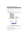
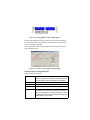
4.3 EDIT Program ........................................................................... 77
4.3.1 User interface ......................................................................... 77
Figure 4.41: MULTIPROG software user interface .............. 77
Figure 4.42: Create New Program ......................................... 77
Figure 4.43: Program editing worksheet ............................... 78
4.3.2 Create a Contact Network ...................................................... 78
Figure 4.44: Program editing window ................................... 78
Figure 4.45: Ladder Tool Bar ................................................ 79
Figure 4.46: Ladder Diagram Example ................................. 79
Figure 4.47: Default setting of C000 ..................................... 79
Figure 4.48: Contact/Coil Property editing example ............ 80
Figure 4.49: Contact/Coil type selection ............................... 80
Figure 4.50: Data type, initial value, I/O address setting in
Contact/Coil property ....................................... 81
Figure 4.51: Contact/Coil Ladder example ........................... 82
xiii
Table of Contents
Figure 4.52:
Figure 4.53:
Figure 4.54:
Figure 4.55:
Contact/Coil name editing ................................ 83
Contact/Coil type selection ............................... 83
Contact/Coil Common property setting ............ 84
Contact/Coil Ladder example with edited
name .................................................................. 85
4.4 Make / Compile your Project..................................................... 86
Figure 4.56:
Figure 4.57:
Figure 4.58:
Figure 4.59:
Project windows in main program .................... 86
Compiler/Debug tool bar .................................. 86
Compiler/Debug message window ................... 86
Build/Errors/Warning pages selection in
Compiler/Debug message window ................... 87
Figure 4.60: Warning page selection in Compiler/Debug
message window ............................................... 87
Figure 4.61: Warning page in Compiler/Debug message
window ............................................................. 87
4.5 Download your Project.............................................................. 88
Figure 4.62: Project Control Dialog selection in main program
tool bar .............................................................. 88
Figure 4.63: Project Control Dialog ...................................... 88
Figure 4.64: Configuration program download process flow
chart .................................................................. 89
Figure 4.65: Stop PLC CPU via Project Control Dialog ....... 89
Figure 4.66: Reset PLC CPU via Project Control Dialog ..... 89
Figure 4.67: Download program into PLC CPU via Project
Control Dialog .................................................. 90
Figure 4.68: Bootproject download function selection in
Download dialog ............................................... 90
Figure 4.69: Bootproject download percentage .................... 90
Figure 4.70: Bootproject activate function selection in
Download dialog ............................................... 91
4.6 Run Your Project ....................................................................... 93
Figure 4.71: Software Information Dialog ............................ 93
4.7 Online Debug Mode and Force Tools ....................................... 94
Figure 4.72: Open Debug Mode in Compiler/Debug tool
bar ................................................................... 94
Figure 4.73: Online Debug Mode ......................................... 94
Figure 4.74: Debug Mode result in ladder diagram .............. 95
Figure 4.75: "Force" True setting in Debug Dialog .............. 95
Figure 4.76: Contact/Coil "Force ON" status ........................ 97
Figure 4.77: Reset the normal value by resetting force ......... 97
4.8 Tutorial 2.Make a cross-compiling project................................ 98
BAS-2000 series User Manual
xiv
Figure 4.78:
Figure 4.79:
Figure 4.80:
Figure 4.81:
Figure 4.82:
Figure 4.83:
Figure 4.84:
Figure 4.85:
Figure 4.86:
Figure 4.87:
Figure 4.88:
Figure 4.89:
Figure 4.90:
Drag out the network length in ladder .............. 98
Network line in ladder ...................................... 98
Edit Wizard tool bar .......................................... 98
Function Block Windows ................................. 99
Timer On-Delay function block property
setting dialog ..................................................... 99
Timer On-Delay program example ................. 100
Present Time input pin in Timer On-Delay
block ............................................................... 100
Variable Properties setting dialog for variable
name of "present time" input .......................... 101
Elapsed Time output pin in Timer On-Delay
block ............................................................... 101
Variable Properties setting dialog for variable
name for "elapsed time" output ...................... 102
Data Type selection for "Elapsed Time" ........ 102
Data Type correct setting for "Elapsed Time" 103
Complete Timer On-Delay program ............... 103
4.9 Online Debug for Cross-Compiling Language Project. .......... 104
Figure 4.91: Timer On-Delay program debug .................... 104
Figure 4.92: Digital Input force on to trigger Timer
On-Delay function ......................................... 104
Figure 4.93: Timer is during count down ............................ 105
Figure 4.94: On-Delay Time up and output coil is triggered
to be on ........................................................... 105
Appendix A User Interface .............................................. 108
Figure A.1:
Figure A.2:
Figure A.3:
Figure A.4:
Figure A.5:
Figure A.6:
Figure A.7:
Figure A.8:
Menu Bar ........................................................ 108
Tool Bar operation guide ................................ 110
Move/Resize Tool Bar .................................... 111
Tool Bar in main program .............................. 111
Main Screen in main program ........................ 111
Status Bar ........................................................ 111
Project Tree pages ........................................... 112
Message Window ............................................ 113
Appendix B Building Automation function block
libraries ........................................................ 116
Figure B.1: "Edit Wizard" in Tool Bar .............................. 116
Figure B.2: Function Block Window ................................. 116
Figure B.3: "Properties" in "Main*" .................................. 117
xv
Table of Contents
Figure B.4: "Plc/Processor" page of "Properties" in
"Main*" ........................................................... 117
Figure B.5: Select list of "PLC Type" ............................... 118
Figure B.6: Select "IPC 30" for "PLC Type" ..................... 118
Figure B.7: Program edit work sheet ................................. 119
Figure B.8: Function Block groups list .............................. 119
Figure B.9: BAS Function Block list ................................. 120
Figure B.10: Stage Cooling Control Function Block ........... 120
Figure B.11: Modulating Cooling Control Function Block . 121
Figure B.12: Stage Heating Control Function Block ........... 122
Figure B.13: Modulating Heating Control Function Block . 123
Figure B.14: Heat Pump Reversing Valve Control Function
Block ............................................................... 124
Figure B.15: Setpoint Reset Calculation Function Block .... 124
Figure B.16: Economizer Control Function Block .............. 125
Figure B.17: Enthalpy Calculation Function Block ............. 126
Figure B.18: Single Speed Fan Control Function Block ..... 126
Figure B.19: VFD Fan Control Function Block .................. 127
Figure B.20: Return Fan Tracking Function Block ............. 127
Figure B.21: Sliding Window Smoothing Function Block .. 128
Figure B.22: Sliding Window Smoothing Function Block .. 128
Figure B.23: Device Supervisor Control Function Block .... 129
Figure B.24: Schedule Control Function Block ................... 129
Figure B.25: Optimum Start/Optimum Stop Control
Function Block ................................................ 130
Figure B.26: Alarm Function Block .................................... 130
Figure B.27: Minimum On/Off Timer Function Block ....... 131
Figure B.28: Delay Timer Function Block .......................... 131
Figure B.29: Modulating Control Function Block ............... 132
Figure B.30: Modulating Control with Reset (Generic) Function
Block ............................................................... 132
Figure B.31: Staged Control (Generic) Function Block ...... 133
Figure B.32: Staged Control with Reset (Generic) Function
Block ............................................................... 133
Figure B.33: Generic Alarm Function Block ....................... 134
Figure B.34: Signal Inversion Function Block .................... 134
Figure B.35: Staged Rooftop HVAV Unit Example ........... 135
Figure B.36: Heat Pump HVAC Unit w/ Auxiliary Heat
Example ......................................................... 136
Figure B.37: Fan Coil HVAC Unit Example ....................... 136
Figure B.38: Built up Air Handling HVAC Unit w/ VFDs
Example .......................................................... 137
BAS-2000 series User Manual
xvi
Appendix C BAS-2000 Utility Operation Guide............ 140
Figure C.1:
Figure C.2:
Figure C.3:
Figure C.4:
Figure C.5:
Figure C.6:
Figure C.7:
Figure C.8:
Figure C.9:
Figure C.10:
Figure C.11:
Figure C.12:
Figure C.13:
Figure C.14:
Figure C.15:
Figure C.16:
Figure C.17:
Figure C.18:
Figure C.19:
Figure C.20:
Figure C.21:
BAS-2000 utility software start screen ........... 140
Configuration COM port setting ..................... 141
Module Search Dialog .................................... 141
Searching BAS-2000 Module ......................... 142
The BAS-2520 being found by utility ............ 142
The BAS-2020 I/O module under BAS-2520
tree list ............................................................ 143
The BAS-2020 I/O channels configuration
pages ............................................................... 143
The analog input signal type selection ............ 144
The analog input zero calibration dialog ........ 144
The analog input span calibration dialog ........ 145
The analog input channels configuration being
updating .......................................................... 145
The analog output channels configuration
pages ............................................................... 146
The analog output signal type selection .......... 146
The analog output zero calibration dialog ...... 147
The analog output span calibration dialog ...... 147
The analog output channels configuration being
updating .......................................................... 148
The digital input/output channels configuration
pages ............................................................... 148
The digital output channel 1 in "OFF" status . 149
The digital output channel 1 in "ON" status ... 149
The configuration file save function ............... 150
The configuration file download function ...... 150
Appendix D I/O Address MODBUS Mapping Table .... 152
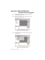
Appendix E BAS-2514/BAS-2520 Controller Firmware
Upgrade ........................................................ 156
Figure E.1:
Figure E.2:
Figure E.3:
Figure E.4:
KW "Ressource" dialog .................................. 156
KW "Download" dialog .................................. 156
Firmware file selection ................................... 157
Firmware downloading process ...................... 157
xvii
Table of Contents
BAS-2000 series User Manual
xviii
1
CHAPTER
2
System Overview
Chapter 1 System Overview
1.1 Introduction
BAS-2000 series Softlogic Digital Controller BAS-2514 & BAS-2520
The Advantech BAS-2000 series is the control system for Building
Automation Control Application. BAS-2520 series controller is a
stand-alone controller with the concept of typical DDC (Direct Digital
Controller) in BA system. For examples, it is designed with universal I/O,
wall mounting thin case and it is also embedded BA control algorithm for
HVAC, lighting, security ……. Applications.
This powerful, stand-alone controller is very easy to learn and use.
BAS-2000 series controllers use the KW softlogic as its control center.
It is fully compatible with IEC61131-3 standard. User can use multiple
languages such as the Function Block Diagram (FBD), Sequential Flow
Chart (SFC), Ladder Diagram (LD), Structure Text (ST) and Instruction
List (IL) for control function configuration. It would reduce engineer
efforts to learn proprietary programming tool and save the investment
cost and schedule in proprietary system.
The BAS-2000 series controllers adopt MODBUS/RTU protocol which is
the most popular and cost effective solution for field data communicating,
and the transmission speed is up to 115.2Kbps. By using MODBUS/RTU
protocol, it will be much easier to integrate the control data between
BAS-2000 series controller and field machinery such as compressor,
chiller, inverter and power panel. And the BACnet MS/TP protocol will
be the optional protocol in nearly future.
BAS-2000 series User Manual
2
1.2 Features
• Process IEC-61131 standard with rich development environment
• Cross-Language programming
• Large memory size for programming and storage
• Real time multi-task engine
• Free pre-defined function library
• Powerful debug / diagnostic / simulation / force tools
• Open Standard connection - Modbus standard Interface
• Online editing & partial download
• RS-232/485 communication ability
• Built-in ROM and RAM disk for programming
• Built-in real-time clock and watchdog timer
1.2.1 Process IEC 61131-3 standard with rich
development environment
The standard IEC 61131-3 has been established to standardize the
multiple languages, sets of instructions and different concepts existing in
the field of automation systems. The great variety of control concepts has
led to an incompatibility between the different control platforms and
manufacturers. The result was a great effort to be made for training,
hard- and software investments.
IEC 61131-3 defines the syntax of 5 programming languages, defines a
certain representation and describes the different elements which can be
used in the language.
The programming languages can be differentiated by the physical a
ppearance into 2 textual languages and 3 graphical languages.
Table 1.1: Programming Languages Table
Textual Languages
Graphical Languages
Instruction List (IL)
Structured Text (ST)
Function Block Diagram (FBD)
Ladder Diagram (LD)
Sequential Function Chart (SFC)
3
Chapter 1
1.2.2 Cross-Language Programming
For some project integrate and scalable issues, cross-language can help
you to choose the different language for your project. For example, you
can use ladder (LD) on the simple I/O module control or simple logical
expression and use Function Block (FB) on process control for more
advanced expression and use Sequential Function Chart (SFC) for system
configuration in hybrid control system such as Water Treatment.
1.2.3 Large memory size for programming and storage
BAS-2000 series controllers - BAS-2514 and BAS-2520 support 640KB
system memory and 1MB flash memory for programming use. It is large
than traditional pc based controller. With this large memory, you can
expand your program size for more tags and expressions. Beside, the
storage size is also growing up with this large memory size.
For System Use
256 KB system ROM
256 KB flash memory
512 KB SRAM, up to 32 KB with battery backup
BAS-2000 series User Manual
4
1.2.4 Real time multi-task engine
BAS-2514/BAS-2520 provides the multi-task and multi-program
environment. BAS-2514/BAS-2520 communication, data process and
I/O access tasks are working independent, so the system can work with
higher performance and efficiency.
1.2.5 Pre-defined function library
Advantech MULTIPROG provides many pre-defined function library
such as maximum of strings as string function block, Convert REAL to
INT as type convert function block. It helps you to build up your program
more conveniently. It is more convenient than the traditional control
programming tools. With this pre-defined function, you can make your
project easier in timer control, variable type convert or strings convert,
etc.
In addition, user can define their own function block for common use
function or special domain know how.
1.2.6 Powerful debug/diagnostic/simulation/force tools
Advantech MULTIPROG provides lots of powerful tools for debug,
diagnostic, simulation and force function. It shows friendly interfaces
when you use these tools. With debug / diagnostic tools, you can make it
easier on trouble shooting. Advantech MULTIPROG simulator supports
program verification offline directly on your PC. This is great in case you
are developing logic and you do not have access to a controller. To
activate an I/O simply click on the LED you want to energize and your
logic executes as if it was a real I/O. The result? The program operation is
the same as if you actually were connected to the controller, so all the
debug tools are fully functional: power and logic flow, I/O force and
overwriting.. With force tools, you can check more exception situations
and check if the project handling right or wrong. It prevents the damage
for you.
5
Chapter 1
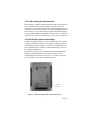
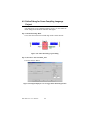
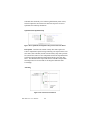
1.2.7 Open Standard connection - Modbus standard
Interface
Figure 1.1: Communication with HMI Station
With Modbus protocol, you can integrate your system thru most of HMI
SCADA system or OPC Server and even HMI SCADA with OPC Server.
It helps you to integrate control I/O system and plant system easier.
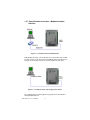
Figure 1.2: Communication with Configuration Station
The configuration & control application program can be downloaded
through PORT1 RS-232.
BAS-2000 series User Manual
6
1.2.8 Online editing & partial download
Online editing is a MUST even though many packages do not support it.
It is unacceptable to shut down the machine or process to perform
maintenance, not to mention how difficult it is to debug when you have to
switch back and forth from program to run mode. MULTIPROG supports
online editing so you can make changes and then download the changes
to the controller WITHOUT stopping the machine or process. It helps you
to maintain your system easier and save the cost for your system process.
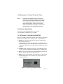
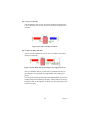
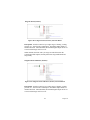
1.2.9 RS-232/485 communication ability
The BAS-2514/BAS-2520 has two serial communication ports, giving it
excellent communication abilities. This facilitates its ability to control
networked devices. Refer to Figure 1-1, COM1 is a dedicated RS-232
port (configuration port), COM2 is a dedicated RS-485 port. These two
ports allowed the BAS-2514/
BAS-2520 to satisfy diverse communication and integration demands.
With this communication ports, you should not to buy more I/O
communication device and save more costs. You can also extend your
system structure by using these communication ports.
Figure 1.3: BAS-2514/BAS-2520 Communication Ports
7
Chapter 1
1.2.10 Built-in ROM and RAM disk for programming
The BAS-2514/BAS-2520 has built-in Flash Memory and SRAM for file
downloading, system operation and data storage. It provides 1 MB file
system, 384 KB free for users to download programs. There are also
512KB SRAM to provide the memory needed for efficient application
operation and file transfer. Moreover, users are allowed to decide the
battery backup memory size up to 384KB in the SRAM.
1.2.11 Built-in real-time clock and watchdog timer
The BAS-2514/BAS-2520 also includes a real-time clock and watchdog
timer. The real-time clock records events while they occur. The watchdog
timer is designed to automatically reset the microprocessor if the system
fails. BAS-2514/BAS-2520 provides three kinds of watchdog time for
Operating System Watchdog, KW application watchdog, Modbus server
communication watchdog. It will shift up the reliability of system. And
makes the BAS-2514/BAS-2520 ideal for use in applications which
required a high level of system stability.
BAS-2000 series User Manual
8
1.3 BAS-2514/BAS-2520 Specification
1.3.1 System
•
•
•
•
•
•
•
•
•
•
•
•
•
•
•
CPU: 80188-40, 16-bit microprocessor
Operating system: Boot ROM-DOS
1 MB files system for users' application
256 KB system ROM (for system use)
256 KB flash memory (for system use)
SRAM: 512 KB
Battery backup: 32 KB (16 KB for data, 16 KB for KW retain data)
Timer BIOS: Yes
Real-time clock: Yes
Watchdog timer: Yes
Operating System Watchdog
KW application watchdog
Modbus server communication watchdog
COM1: RS-232, 3 Wires (configuration port)
COM2: RS-485, Terminal
I/O capacity for BAS-2514: 14 onboard I/O (4AI/8DI/4AO/4DO), up to
74 I/O point (expanded by BAS-2020/BAS-2014 I/O Expansion
Module)
I/O capacity for BAS-2520: 20 onboard I/O (4AI/8DI/4AO/4DO), up
to 80 I/O point (expanded by BAS-2020/BAS-2014 I/O Expansion
Module)
Analog Input type:
2,3 wired Pt-100, Pt-1000
3K, 10K Thermistor
0 to 10VDC signal
4 to 20 mA signal
A/D resolution: 16-bit
Selectable input type by Software
Digital Input type:
Dry contact
Logic level 1 : Close
Logic level 0 : Open
Wet Contact (Check external power voltage 15Vdc)
9
Chapter 1
Logic level 1 : +10 to 30Vdc
Logic level 0 : +3Vmax
support 1KHz pulse input (Check frequency )
• Analog output : (please be noticed that BAS-2000 analog output
channel cannot be used by common ground wiring)
0 to 10Vdc output
4 to 20 mA output
D/A resolution: 8-bit
Selectable input type by Software
• Digital output:
Relay output : AC240VAC @ 3A, with LED indicator
• CPU power consumption: 2.5 W
• Status display: Power, RUN, Communication, Battery
1.3.2 RS-485 interface (COM2) (Connect to host PC)
•
•
•
•
•
Signals: DATA+, DATAMode : Half duplex, multi-drop
Connector: Screw terminal
Transmission speed: Up to 38400 bps
Max transmission distance: 4000 feet (1220 m)
1.3.3 Power
• Power Requirement : 24 VAC or 17 ~ 35 Vdc ("L" : +Vdc, "N" : -Vdc)
• Power consumption: 2.5 W
1.3.4 Environment
•
•
•
•
Operating temperature: -10° to 60° C (14° to 140° F)
Storage temperature: -25° to 85° C (-13° to 185° F)
Humidity: 5 to 95 %, non-condensing
Atmosphere: No corrosive gases
BAS-2000 series User Manual
10
1.3.5 Dimensions : 171mm X 242 mm X 35 mm
NOTE:
Equipment will operate below 30% humidity.
However, static electricity problems occur much
more frequently at lower humidity levels. Make
sure you take adequate precautions when you
touch the equipment. Consider using ground
straps, anti-static floor coverings, etc. if you use
the equipment in low humidity environments.
1.3.6 Software Specification
• Real Time O.S: KW PROCONOS (Up to 16 tasks)
• Programmable Code/Data Size: up to 64 KB
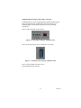
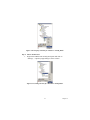
1.3.7 LED Status of the BAS-2514/BAS-2520
There are four LEDs on the BAS-2514/BAS-2520 front panel. The LED's
indicate BAS-2514/BAS-2520's operating status, as explained below:
(4) PWR: power indicator. This LED is on whenever the BAS-2514/
BAS-2520 is powered on.
If BAS-2514/BAS-2520 system fails, the power indicator will be
regular blinking per 500ms. You should stop your program and click
on the error message, the system will return to normal power indicator mode.
(2) COMM: COM2 communication indicator. This LED blinks whenever the host PC and the BAS-2514/BAS-2520 are communicating.
(3) RUN: CPU operation indicator, this LED shall blink in normal condition. If the CPU fails, the LED will be latched.
(4) Battery: battery status indicator. This LED will be on whenever the
SRAM backup battery is low. If battery low, please contact with
Advantech support.
Figure 1.4: BAS-2514/2520 LED and Jumper
11
Chapter 1
1.4 Limitation
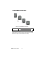
1.4.1 I/O Quantity
BAS-2520 provides 20 onboard I/O and BAS-2514 provides 14 onboard
I/O, the I/O can also expanded with BAS-2020/BAS-2014 I/O Expansion
Module through local bus (the max. length of local bus cable is up to 2.0
meters). The I/O capacity of BAS-2520 is up to 80 points and the I/O
capacity of BAS-2514 is up to 74 points.
Figure 1.5: BAS-2000 Controller with I/O Expansion Module Connection
1.4.2 Memory size
BAS-2514/BAS-2520 enlarges the memory size for programming use
and system unit.
It contain system ROM, flash memory, SRAM and files system memory
for user's application,
• 256 KB system ROM (for system use)
• 256 KB flash memory (for system use)
• SRAM: 512 KB
• Battery backup: 32 KB (16 KB for data, 16 KB for KW retain data)
BAS-2000 series User Manual
12
2
CHAPTER
2
Installation Guidelines
Chapter 2 Installation Guidelines
2.1 System Requirements
2.1.1 Host Computer Requirements
1.
IBM PC compatible computer with 486 CPU (Pentium is
recommended).
2.
Microsoft 98/2000/XP/NT 4.0 (SP3 or SP4) or higher versions.
3.
At least 32 MB RAM.
4.
20 MB of hard disk space available
5.
VGA color monitor.
6.
2x or higher speed CD-ROM.
7.
Mouse or other pointing devices.
8.
At least one standard RS-232 port (e.g. COM1, COM2).
9.
One RS-485 card or RS-232 to RS-485 converter (e. g.
ADAM-4520) for system communication.
2.1.2 BAS-2514/BAS-2520 Requirements
1.
One BAS-2520 (or BAS-2514) main unit.
2.
One BAS-2000 User Manual
3.
BAS-2020 (or BAS-2014) with Local Bus Cable (Optional)
4.
24VAC Power supply for BAS-2514/BAS-2520 (the BAS-2020/
BAS-2014 will be powered by BAS-2514/BAS-2520, the additional
power supply is unnecessary)
5.
One RS-232 straight through DB-9 cable
BAS-2000 series User Manual
14
2.2 Hardware Installation
2.2.1 Mounting
The BAS-2514/BAS-2520 controller can be installed on a panel or Wall
Figure 2.1: BAS-2000 Modules Wall Mounting Holes
2.2.2 Jumper Settings and DIP Switch Settings
This section tells you how to set the jumpers and DIP switches to
configure your BAS-2514/BAS-2520 controller. It gives the system
default configuration and your options for each jumper and dip switch.
There is one 8-pin DIP switch on backplane board. In this section, the
BAS-2520 will be the example for this tutorial case (all of the jumper and
DIP switch setting is the same for both of BAS-2514 and BAS-2520).
System Mode Setting : RUN/Initial
Figure 2.2: CPU Jumper Setting
15
Chapter 2
Device ID Setting:
You can set up your device ID by change the DIP Switch 1-5 beside
BAS-2514/BAS-2520.
Figure 2.3: DIP switch for Device ID
ID Setting :
Please refer the following example for ID setting.
ID 1 : 1 ON only
ID 2 : 2 ON only
ID 3 : 1 & 2 ON (1+2=3)
ID 4 : 4 On only
ID 10 : 2 and 8 ON (2+8=10)
ID 15 : 1, 2, 4, 8 ON (1+2+4+8=15)
COM Port Setting :
S1 ON : COM Port 2 RS-485 Enabled
S1 OFF : COM Port 1 RS-232 Enabled
Note : COM1 and COM2 cannot be used in the same time.
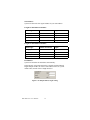
Baud Rate Setting
Baud Rate
S2
S3
9600 bps
OFF
OFF
19200 bps
OFF
ON
38400 bps
ON
OFF
115.2K bps
ON
ON
BAS-2000 series User Manual
16
2.3 BAS-2514/BAS-2520 System Wiring and
Connections
This section provides basic information on wiring the power supply, I/O
units, communication port connection and programming port connection.
2.3.1 Power supply wiring
The BAS-2514/BAS-2520 was designed with using power supply
24VAC, the typical power requirement in Building Automation device.
Please refer the following power wiring drawing .
Note:
The wires used should be sized at least 2 mm.
Figure 2.4: BAS-2514/BAS-2520 Power Wiring
2.3.2 I/O modules wiring
The system uses a plug-in screw terminal block for the interface between
I/O modules and field devices. The following information must be
considered when connecting electrical devices to I/O modules.
1.
The terminal block accepts wires from 0.5 mm2 to 2.5 mm2.
2.
Always use a continuous length of wire. Do not combine wires to
make them longer.
3.
Use the shortest possible wire length.
4.
Use wire trays for routing where possible.
5.
Avoid running wires near high energy wiring.
6.
Avoid running input wiring in close proximity to output wiring
where possible.
7.
Avoid creating sharp bends in the wires.
17
Chapter 2
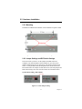
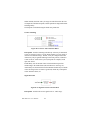
2.3.3 System Network Connection
The BAS-2514/BAS-2520 has two communication ports. These ports
allowed you to program, configure, monitor, and integrate the remote
devices.
Network Connection for System Configuration and Download
The BAS-2514/BAS-2520 has a programming port with a 3 wires
terminal connection. This port (PORT1) allows you to program, configure, and troubleshoot the BAS-2514/BAS-2520 from your host computer.
The programming port has an RS-232 interface and only uses TX, RX,
and GND signals. The cable connection and the pin assignment are as
follows:
PC COM Port
BAS-2514/BAS-2520 Port1
CD
1
RX
2
RX
TX
3
TX
DTR
4
GND
GND
5
DSR
6
RTS
7
Figure 2.5: System Configuration Wiring
BAS-2000 series User Manual
18
Simulation Mode Setting for BAS Utility connection
The BAS-2000 I/O can be configured and be calibrated by BAS utility.
Before using BAS utility, the BAS-2000 controller must be set as
simulation mode. For the detail steps, please refer the following
descriptions.
Step 1:Set the Controller mode as "RUN"
Figure 2.6: CPU jumper setting for simulation mode
Step 2:Set all of the DIP switch of "NODE ID" to be "OFF"
Figure 2.7: CPU DIP switch setting for simulation mode
Step 3:Connect the RS-232 cable to Port 1
Step 4:Run BAS Utility software
19
Chapter 2
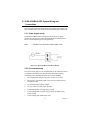
RS-485 Network Connection for System Monitoring and Integration
The BAS-2514/BAS-2520 provides RS-485 interfaces for multi-drop
network integration. The PORT2 is a dedicate RS-485 interface (Screw
terminals DATA- and DATA+ are used for making the PORT2 RS-485
connections). Usually, you will need to prepare an ADAM-4520 RS232/
485 converter to link with host PC for data monitoring See Figure 2-11.
Figure 2.8: System Monitoring Wiring
BAS-2000 series User Manual
20
2.4 BAS-2514/BAS-2520 System Configuration
2.4.1 Standalone Controller Wiring
Figure 2.9: BAS-2000 SoftLogic Digital Controller
Figure 2.10: BAS-2000 Analog Input Channel Wiring
21
Chapter 2
Figure 2.11: BAS-2000 Digital Input Channel Wiring
Figure 2.12: BAS-2000 Analog Output Channel Wiring
BAS-2000 series User Manual
22
Figure 2.13: BAS-2000 Digital Output Channel Wiring
23
Chapter 2
2.4.2 System Multi-Connection Wiring
Figure 2.14: BAS-2000 System Connection
RS-485 Data +
RS-485 Data -
In multi-connection, you should adjust device ID by change DIP switch,
please refer to chapter 2.2.2 Device ID DIP switch setting.
BAS-2000 series User Manual
24
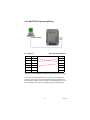
2.4.3 MULTIPRO Programming Wiring
PC COM Port
CD
1
RX
2
BAS-2514/BAS-2520 Port1
RX
TX
3
TX
DTR
4
GND
GND
5
DSR
6
RTS
7
Figure 2.15: BAS-2000 MULTIPROG programming station wiring
You can run the MULTIPROG from your Host PC and make some
program or procedure in it and download the program to BAS-2514/
BAS-2520 thru COM1. After the program is downloading into system,
BAS-2514/BAS-2520 will start running the program automatically.
25
Chapter 2
2.4.4 HMI SCADA System Wiring
Figure 2.16: HMI SCADA System
You can connect BAS-2514/BAS-2520 to the HMI SCADA System thru
MODBUS protocol from COM 2 RS-485. If the HMI SCADA is not
including MODBUS OPC Server, you have to install an individual
MODBUS OPC Server in your system such as ADAMView, GeniDAQ.
If the MODBUS OPC Server is included, you can active the function to
get connection with BAS-2514/BAS-2520, such as ASTUDIO.
BAS-2000 series User Manual
26
3
CHAPTER
2
Software Installation
Chapter 3 Software Installation
3.1 Introduction
KW MULTIPROG IEC 61131 programming system supports all IEC
61131-3 programming languages. According to the task to be handled,
programmer experience level, and your company standards, you may
choose one of the five standardized programming languages.
KW MULTIPROG runs as a 32 bit application on all standard PC
Windows systems and allows intuitive programming with a clear
structure:
• User interface and use are strictly oriented to the Windows standard.
• The Edit Wizard displays the available elements in all editors while
programming.
• An extensive context-sensitive HTML help system supports you on all
levels: from questions about the general use, via information about
function, up to the back-ground of the IEC 61131-3 standards.
• Cross-References automatically create an overview of the used data.
• Self-definable and dockable toolbars.
• In a few minutes, you will learn the basic steps to create a control
program by the online help video sequences.
Fully Support IEC 61131-3 Programming Languages
• Instruction List (IL)
• Structured Text (ST)
• Function Block Diagram (FBD)
• Ladder Diagram (LD)
• Sequential Function Chart (SFC)
*All programming languages can be mixed within one project.
Cross-compiling
The basic languages of the IEC 61131-3 standard; i.e., FBD, LD and IL,
can be cross-compiled to each other including their comments. Program
code, which has been written in ST, can be compiled to any of the three
basic languages.
BAS-2000 series User Manual
28
On-line Language Switching for True International Support
The software, including help systems and documentation, is available in
English, German, French, Japanese and Chinese. Online, even the user
generated project documentation, can be switched into any language as
well.
Graphic Editor
The fully graphic editor allows a completely free placing of objects as
well as a network-oriented handling. You may choose the method which
best suits your application, and use the functions of the editor by which
you can quickly create your programs in LD/FBD or SFC. The editor supports:
• Mixing of LD, FBD and SFC in a single worksheet.
• Placing of objects at a sizeable grid.
• Insertion of new elements into existing networks without any
limitations.
• Moving of single objects or networks.
• Auto routing for an automatic connection.
• Display of graphics in the functions and function blocks to visualize
their purpose.
• Opening of the code by a double click on the appropriate user defined
functions and function blocks.
• Different colors for functions and function blocks from the firmware
library, the user library and the project.
Textual Languages
The text editor allows you to create your programs fast and easily. You
are supported by various functions:
• Syntax highlighting indicates the keywords of the program.
• IntelliSense automatically completes your variable names, structure
elements and function block perimeters.
• The Edit Wizard eases the editing by displaying the available elements
and function blocks.
• The menu adapts itself context-sensitively.
29
Chapter 3
Reliability by Experience
KW MULTIPROG is based on an embedded softlogic controller that has
been applied in the automation industry since 1991. With over 250,000
runtime installations worldwide, a sophisticated and reliable product is
available which is continuously adapted to new technologies.
Preemptive Multitasking
KW MULTIPROG is based on a standard multi-tasking operating system
and supports pre-emptive scheduling. This allows the exact prediction of
the time behavior of user tasks, down to 1 millisecond resolution. A
watchdog is assigned to each user task and will activate the appropriate
system tasks to realize corrective action if a real-time violation arises. In
this way, supervision is guaranteed. The programming of system tasks
allows a differentiated reaction from the application towards runtime
errors (exception handling: watchdog, division by zero, etc.) and changes
in the operational mode (e.g., stop to run, boot sequence). Highly efficient
communication functions support OPC, remote maintenance and
programming.
Hardware Requirements
Device
Minimum
Recommended
IBM compatible PC with
Pentium Processor
200 MHz
350 MHz
System RAM
64 MB
128 MB
Hard Disk Space
60 MB free space
CD ROM Drive
Required
VGA Monitor Color
Settings Resolution
256 Colors
800 x 600
RS-232 Interface
1 Port
Mouse
Recommended
True Color
1024 x 768
Software Requirements
• Microsoft Windows 98
• Microsoft Windows NT 4.0 SP5 or Windows 2000/XP
• Microsoft Internet Explorer 4.02 and above
BAS-2000 series User Manual
30
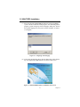
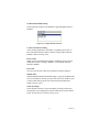
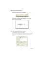
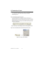
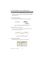
3.2 MULTIPRO Installation
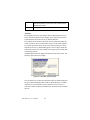
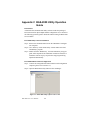
(1) Insert the Advantech MULTIPROG Software CD into CD-ROM,
system will auto launch the install program. After launching install
program, system will pop up "Select Language" dialog box. Choose
the suitable language for your system. (In this example, we choose
U.S. English)
Figure 3.1: Language selection page
(2) After select the language option, the next dialog box will be shown
up. All components of KW Software will show in this screen.
Figure 3.2: MULTIPROG software installation start screen
31
Chapter 3
MULTIPROG 3.3
The IEC 61131 programming system MULTIPROG supports all IEC
61131-3 programming languages. According to the task to be handled,
the experience and the company standard, you may choose one of the five
standardized programming languages. The use of MULTIPROG offers
you many advantages. Our long-term experience in the automation
industry guarantees you a sophisticated software product.
ProConOS
Programmable Controller Operating System is a real time, multitasking
IEC- 61131 compliant PLC operating system designed to be embedded in
almost any hardware. Since it is easily integrated with existing runtime
programs and firmware packages, the control suppliers can offer an IEC
compliant system maintaining their own individual unique features and
capabilities.
√ Reliability due to expertise
ProConOS‚ has been applied in the automation industry since 1991. Thus
a sophisticated and reliable product is available, which matches current
requirements and which are continuously adapted to new technologies.
√ Advantages due to a clear structure
The modular software structure offers:
• Multiple interfaces for system development engineers
• Easy realization of manufacturer-specific features
• Fast integration into existing systems such as CNC, robotics or motion
control
Standard real time operating systems by well-known manufacturers form
the basis of ProConOS.
OPC Server
The ProConOS OPC Server provides the gateway to the standard
Windows world and to Windows CE.ProConOS OPC Server handles the
data exchange between Windows applications (e.g. visualization, data
base, ...) and ProConOS PLCs via the manufacturer independent
client/server interface OPC (OLE for Process Control). The OPC Server
can be applied for the communication with a PLC or in distributed PLC
networks.
BAS-2000 series User Manual
32
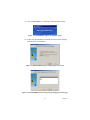
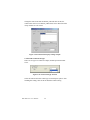
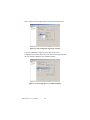
(3) Click on MULTIPROG 3.3 and bring out the installation wizard.
Figure 3.3: MULTIPROG software installation wizard
(4) In this step, the installation wizard will show the welcome message
and other notes for installation.
Figure 3.4: MULTIPROG software setup program start screen
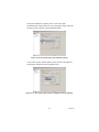
Figure 3.5: MULTIPROG software setup program language selection page
33
Chapter 3
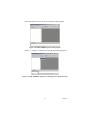
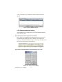
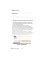
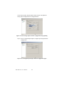
(5) Select the default language supported by MULTIPROG and click
"Next" button to continue installation.
Note:
MULTIPROG supports English, German, French,
Japanese language mode.
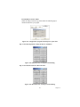
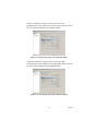
(6) Select the program manager group for yourself. We suggest you to
set the Groups name to "Advantech\BAS-2000".
Figure 3.6: MULTIPROG software Program Manager Group setup page
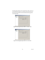
(7) Select the destination folder to install MULTIPROG. You can choose
the folder yourself or use the default install path for "C:\KWSoft ". It
is recommended that you install the MULTIPROG on the path for
"C:\BAS-2000". Make sure your setting and click on "Next" to go to
next step.
Figure 3.7: MULTIPROG software installing directory setup page
BAS-2000 series User Manual
34
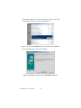
(8) Make sure if those setting before are correct; please click on "Install"
to begin installing. Otherwise click on "Back" to check the setting
for previous steps.
Figure 3.8: MULTIPROG software ready to install
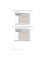
(9) System will enter installing process after clicking Install button.
After the status slide bar reach 100%, the installation is finished.
Figure 3.9: MULTIPROG software installing percentage
(10) After finishing the installation, system will show you the message of
"Installation Successful" and the installed components.
Figure 3.10: MULTIPROG software install successfully
35
Chapter 3
3.3 MULTIPRO Add-ons Installation
(1) After finishing install MULTIPRO program, we need to install the
other Add-On program. Please click on "Multiprog Add-Ons" to
process the installation.
Figure 3.11: MULTIPROG Add-on component installation selection
(2) There are 5 components in Add-on for selection. Please be noticed
the "Advantech Multiprog Add-on" must be installed first.
Figure 3.12: Add-on components selection page
BAS-2000 series User Manual
36
(3) The software InstallShield Wizard will help you to install step by
step.
Figure 3.13: MULTIPROG software Add-on installation welcome page
Figure 3.14: License acceptance page
Figure 3.15: Installation warning page
37
Chapter 3
Figure 3.16: MULTIPROG software Add-on ready to install
(4) Please select the language
Figure 3.17: MULTIPROG software Add-on installation language selection page
Figure 3.18: PLC Type ARM_L_32 Add-on installation welcome page
BAS-2000 series User Manual
38
Figure 3.19: PLC Type ARM_L_32 component ready to install
(5) Installation wizard will initialize the process of installing
"Advantech MULTIPROG Add on".
Figure 3.20: PLC Type ARM_L_32 installation wizard
Figure 3.21: Installation percentage of PLC Type ARM_L_32 Add-on
39
Chapter 3
Figure 3.22: PLC Type ARM_L_32 Add-on component install successfully
(6) Please go back to Multiprog Add-on main manu to select the
"Advantech BAS-2000 Driver" component to install it.
Figure 3.23: Add-on components selection page
(7) The software InstallShield Wizard will help you to install step by
step.
Figure 3.24: Bas-2520 Driver Add-on installation welcome page
BAS-2000 series User Manual
40
Figure 3.25: License acceptance page
Figure 3.26: BAS-2520 Driver Installation information
Figure 3.27: BAS-2520 Driver Installation percentage
41
Chapter 3
Figure 3.28: BAS-2520 Driver Installation completely
3.4 MULTIPROG Registration
After finishing the installation step, you can run MULTIPROG from
Start Menu --> All Program -->Advantech-->BAS-2000-->MULTIPROG
The program will be launch after you click on the icon for MULTIPROG
and show the following welcome screen.
Figure 3.29: MULTIPROG software start screen
BAS-2000 series User Manual
42
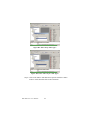
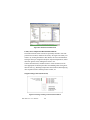
After showing the welcome screen, it will enter the main program.
Figure 3.30: MULTIPROG software main program
Choose "?-->Register" of menu bar to open the Registration dialog box.
Figure 3.31: MULTIPROG software for choosing license register function
43
Chapter 3
Enter the registration code from the key in the license agreement come
with the software package.
Figure 3.32: License code register block
If you enter the correct registration code, the dialog box will close.
Figure 3.33: License register successfully
You can check the license status from "?-->Info" of menu bar.
Figure 3.34: MULTIPROG software "about" information
BAS-2000 series User Manual
44
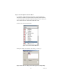
3.5 Uninstall MULTIPROG
To uninstall MULTIPROG, please remove it from Control Panel. You can
just open the control panel by clicking on Start --> Settings --> Control
Panel.
Figure 3.35: Windows Program manual for "Control Panel"
Click on "Add/Remove Programs" icon to enter the uninstall process
Figure 3.36: Select "Add/Remove Programs" in Microsoft Windows
Control Panel
45
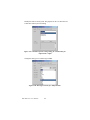
Chapter 3
Find the MULTIPROG 3.3 of currently installed programs, click on the
Change/Remove button to start the uninstall process.
Figure 3.37: Select MULTIPROG software to remove it from Windows
Press the Finish button to perform the uninstall.
Figure 3.38: Windows ready to remove MULTIPROG software
BAS-2000 series User Manual
46
After click on Finish button, the uninstall process will start. After
installation step is finished. The dialog box will be closed.
Figure 3.39: MULTIPROG software un-installation proceeding
47
Chapter 3
BAS-2000 series User Manual
48
CHAPTER
4
2
Getting Started
Chapter 4 Getting Started
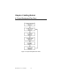
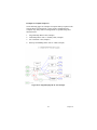
4.1 Project Development Flow Chart
Figure 4.1: Project Development Flow Chart
BAS-2000 series User Manual
50
4.1.1 RUN MULTIPROG
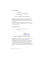
Before starting to create a new project, it is necessary to run the MULTIPROG program. You can run the program from Start menu --> Advantech --> BAS-2000 --> MULTIPROG
After click on MULTIPROG icon, system will come out the welcome
screen of MULTIPROG.
Figure 4.2: MULTIPROG software start screen
4.2 Initial Project
Before starting a new project, you must to open a new project and select
the suitable template file for BAS-2520. After open a new project you can
configure the system and I/O modules for this system.
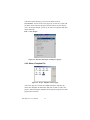
4.2.1 Create a new project
Figure 4.3: Project windows in MULTIPROG main program
51
Chapter 4
After the welcome message, you can see the main screen for
MULTIPROG. You can create a new project by several ways, open with
file menu, click on the new project icon from tools bar or press hot key
(Ctrl + N), In this example, you can try to create a new project with opening the file menu.
File --> New Project
Figure 4.4: Selection manual for creating new project
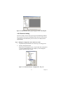
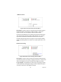
4.2.2 Select a Template File
Figure 4.5: Project Template selection page
After a new project is created, the template dialog box will show up,
choose the "Template for BAS-2520" and click on "OK" to start a new
project. After Choosing the template file the system will go back to main
program area as follow:
BAS-2000 series User Manual
52
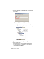
Figure 4.6: MULTIPROG main program page for BAS-2520 template
4.2.3 Resource Setting
Resource setting is used to specify the target for downloading. With the
PLC type IPC you can use 2 simulations at the same time. You can also
specify the real communication port for real device on BAS-2520 for
programming.
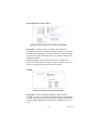
Step 1. Modify the Configuration Name & Resource Name
1.
Expand the Physical Hardware tree menu to go on setting process
2.
Modify Configuration Name
Right click on Configuration: IPC_30 option and click on Properties
to set the configuration name. For example, you can change the
property name for what you want.
Figure 4.7: Selection manu for "Configuration : IPC_30"
53
Chapter 4
3.
Fill in the wanted name (for example : 'BAS2000_Project') and click
on OK button.
Figure 4.8: Property page of "Configuration : IPC_30"
4.
After clicking on ok, the modification is finished. The configuration
name is changed to 'BAS2000_Project : IPC_30'. Please note
"IPC_30" is attached to your project name by system automatically.
Figure 4.9: Worksheet of BAS-2520 after renaming the project
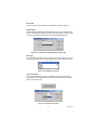
5.
Modify Resource Name
You can just right click on 'Resource : PCOS_DOS' and click on
sub-menu of 'Properties…'. Please change the resource name to
"'BAS2520' and click on OK button.
BAS-2000 series User Manual
54
Figure 4.10: Property selection for "Resource : PCOS_DOS"
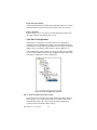
Step 2. Start to Set Resource
1.
Right click on BAS-2520: PCOS_DOS option and click on
"Settings…" option in popup dialog to set the resource.
Figure 4.11: Setting selection for "BAS2520 : PCOS_DOS"
55
Chapter 4
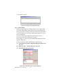
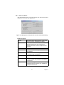
2.
You can see the BAS2520 :PCOS_DOS dialog box will popup as
below
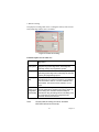
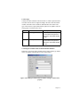
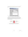
Figure 4.12: Setting page for "BAS2520 : PCOS_DOS"
BAS-2000 series User Manual
56
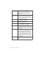
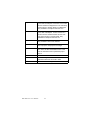
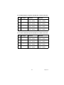
Filed Description
COM
Indicates to which serial port the program is sent.
Simulation
Indicates to which simulation the program is sent.
DLL
Indicates that the program is sent to a
communication DLL. A communication DLL is
necessary, if the communication interface between
the programming system and the PLC and/or the
processor type does not fit together. Only available
if a communication DLL is found in the path
mwtexe\plcname.
Baud
Specifies the baud rate for the communication via
the selected port. This entry has only to be
changed if your hardware needs a different value.
Stopbits
Specifies the number of stopbits for the
communication via the selected port. This entry
has only to be changed if your hardware needs a
different value.
Databits
Specifies the number of the databits for the
communication via the selected port. This entry
has only to be changed if your hardware needs a
different value.
Parity
Indicates the use of a parity bit for the
communication via the selected port. This entry
has only to be changed if your hardware needs a
different value.
Timeout
Specifies the interval in ms for timeout. During this
time interval the programming system tries to
establish the connection to the hardware. If the
time interval is exceeded timeout is displayed.
Stack-Check on
PLC
Activates the Stack-Check on the PLC. The
Stack-Check checks if there are stack overflows.
Activating this checkbox means a loss of
performance but more security.
Array boundary
check on PLC
Activates the array boundary check on the PLC.
The array boundary check checks if all used array
elements are included in the array. If an array e.g.
has 23 elements, it is checked whether more than
23 elements are used in the PLC application.
Activating this checkbox means a loss of
performance but more security.
57
Chapter 4
Force BOOL8 for
Boolean variables
Stores all Boolean variables without direct location
as a byte. Activating this checkbox means a much
higher performance. The resulting code is
changed. If it is not checked the variables are
stored as one bit.
Generate
bootproject during
compile
Generates a bootproject during the compilation
process and not while downloading. This checkbox
can be used to generate a bootproject offline. The
file for the bootproject is called bootfile.pro and is
stored in the resource directory.
DLL:
Specifies the name of the communication DLL.
Only available if DLL is activated.
Parameter:
Specifies the string passed to the DLL. Only
available if DLL is activated.
PDD
Specifies if variables are written to the PDD on the
PLC i.e. the variables can be used with IEC
61131-5 communication function blocks.
OPC
Specifies if variables are written to the *.csv file in
the resource directory. The OPC Server processes
these variables and transfers their actual values to
an OPC Client.
Use reserve
Uses the memory reserve for Patch POU which
has been entered in the dialog 'Data Area'. 'All
POUs' means that the reserve is used for all
POUs. 'Marked POUs' means that the reserve is
used for all POUs which have been marked in the
dialog 'Insert' while inserting the POU or in the
POU properties dialog (tab 'Type'). 'No reserve'
means that the reserve is not used.Recommended
setting: 'All POUs'.
Data area...
Calls the dialog 'Data Area' for setting the memory
areas for user and system flags and the reserve for
POUs.
BAS-2000 series User Manual
58
3. Port Setting and Baud Rate Setting
Before setting the port and baud rate, you should make sure the related
setting of your host PC is fit to your choice. In the example, you can just
set the three area of 'Port', 'Baud rate' and 'Data area…'. Please leave the
other setting as default value.
Figure 4.13: COM Port setting
Filed Description
COM
Indicates to which serial port the program is sent.
Simulation
Indicates to which simulation the program is sent.
DLL
Indicates that the program is sent to a communication
DLL. A communication DLL is necessary, if the communication interface between the programming system and the
PLC and/or the processor type does not fit together. Only
available if a communication DLL is found in the path
mwtexe\plcname.
Port setting:
You can set up the port setting between your local port and BAS-2520.
For example, if you connect your BAS-2520 to your COM 1, please
choose COM1 option in this Port setting.
Note:
(1)You can also choose Simulation option for 32
bits simulation program if there is not any real
device on BAS-2520.
59
Chapter 4
4. Baud Rate Setting
Figure 4.14: Baud Rate setting
Filed Description
Baud
Specifies the baud rate for the communication via the
selected port. This entry has only to be changed if your hardware needs a different value.
Stopbits
Specifies the number of stopbits for the communication via
the selected port. This entry has only to be changed if your
hardware needs a different value.
Databits
Specifies the number of the databits for the communication
via the selected port. This entry has only to be changed if
your hardware needs a different value.
Parity
Indicates the use of a parity bit for the communication via the
selected port. This entry has only to be changed if your hardware needs a different value.
Timeout
Specifies the interval in ms for timeout. During this time interval the programming system tries to establish the connection
to the hardware. If the time interval is exceeded timeout is
displayed.
Baud Rate Setting
For the hardware specification, please follow the limitation for connecting BAS-2520 programming port.
Baud rate: 19200
Stop bits: 1
Data bits: 8
Parity: None
BAS-2000 series User Manual
60
5. Data area setting
The purpose of setting "Data Area" is setting the memory areas for user
and system flags and the reserve for POUs.
Figure 4.15: Data Area setting
Field Description of Non retain area
Start user:
Specifies the address where the memory area for user
flags starts.
End user /
Start system:
It specifies the address where the memory area for the
programming system flags starts. These flags are
internally used by the programming system.
End system:
It specifies the address where the memory area for programming system flags ends. These flags are internally
used by the programming system .
Reserve per
POU:
It specifies the default memory reserve for a POU used
for Patch POU. If no reserve is used it is not possible to
use Patch POU if retain or non-retain variables have
been added. The reserve can be entered in % or in
bytes.
Declare user
memory in I/O
configuration
automatically
Creates automatically a hidden entry (VAR_CONF) in
the I/O configuration containing the memory areas set
in this dialog. This checkbox should normally be
activated for using the settings done in this dialog. Only
for old projects or special I/O configurations this
checkbox should be unchecked.
Note:
Please follow the setting of tutorial, otherwise
BAS-2520 will not work correctly.
61
Chapter 4
Non-retain area setting:
Figure 4.16: Non-retain setting
Start user:
System default Start user value for non-retain is '0', you can't modify this
value.
End user / Start system:
Start system value should follow the Start user value. Please fill '0' here.
End system (max 63999):
System will automatically calculate the system flags end as max value of
End system value. In this tutorial, please fill in the max value '63999'.
Reserve per POU:
Default memory reserve for a POU is used for Patch POU. Please leave
this value as default. The default value is '500'.
BAS-2000 series User Manual
62
Retain area setting:
Figure 4.17: Retain Area setting
Field Description of retain area
Start user:
Specifies the address where the memory area for user
flags starts.
End user /
Start system:
It specifies the address where the memory area for the
programming system flags starts. These flags are internally used by the programming system.
End system:
It specifies the address where the memory area for
programming system flags ends. These flags are internally used by the programming system .
Reserve per
POU:
It specifies the default memory reserve for a POU used
for Patch POU. If no reserve is used it is not possible to
use Patch POU if retain or non-retain variables have
been added. The reserve can be entered in % or in
bytes.
Declare user
memory in I/O
configuration
automatically
Creates automatically a hidden entry (VAR_CONF) in
the I/O configuration containing the memory areas set
in this dialog. This checkbox should normally be activated for using the settings done in this dialog. Only for
old projects or special I/O configurations this checkbox
should be unchecked.
Start user:
System default Start user value for retain is '64000', the value is follow
the End system value.
End user / Start system:
Start system value should follow the Start user value. Please fill '64000'
here.
63
Chapter 4
End system (max 65530):
System will automatically calculate the system flags end as max value of
End system value. In this tutorial, please fill in the max value '65530'.
Reserve per POU:
Default memory reserve for a POU is used for Patch POU. Please leave
this value as default. The default value is '10%'.
4.2.4 Set I/O Configuration
The dialog 'I/O Configuration' is used to edit the I/O configuration
worksheet. The I/O configuration normally contains declarations of the
I/O modules, for example the logical addresses of a module (start and end
address), device declarations (driver name or memory address), etc.
After finishing the resource setting, you can go on setting the I/O module
on your system. Double click on the IO_Configuration option and system
will bring out a dialog box of I/O Configuration.
Figure 4.18: IO_Configuration selection
Step 1. Delete the default I/O module setting:
There will be two I/O modules for system default I/O module setting for
your reference, one for Input module named "in" and the other one for
output module named "out". Please delete the default module from
system to release the memory address setting.
BAS-2000 series User Manual
64
Figure 4.19: I/O configuration page
You can delete default I/O module configuration by simply choose the
module and click on delete as following step.
1. Select I/O module
Figure 4.20: I/O Selection
2. Click on Delete button
Figure 4.21: Delete I/O
65
Chapter 4
3. I/O module is deleted
Figure 4.22: Empty I/O Configuration page
Step 2. Add I/O module
While the connected process is running, the PLC receives input signals
via the I/O modules. These input signals are processed according to the
PLC program. After a working cycle the PLC transmits the output signals
to the I/O modules. The way the PLC handles these signals are set up via
the I/O configuration.
If necessary also the data configuration of the memory area for
non-retentive and retentive variables can be edited.
In this example, you will learn to add a Digital Input and Digital Output
module of BAS-2520.
It is easy to add a new input / output module as following steps:
2.1. Select INPUT tag of I/O Configuration dialog box (Please refer
Fig. 4-21)
2.2. Click on "Add…" button (Please refer Fig. 4-21)
2.3. The Properties dialog box pop up
Figure 4.23: "Add I/O Group" Property dialog box
BAS-2000 series User Manual
66
Field Description of I/O Configuration
'OK'
Confirms the dialog. The settings are entered in
the corresponding page ('INPUT' or 'OUTPUT') of
the dialog 'I/O Configuration'.
'Description'
Calls a description concerning the selected board /
I/O module (see below). If no board is selected,
clicking on this button has no effect.
Name
Specifies the name of the I/O module. The user
can define any name.
Task
Specifies the task, to which the module is assigned
(i.e. which processes the signals for/from the
module). The list box contains all tasks which are
used in the PLC program.
Start address
Specifies the start address of the module. The
location prefix (I for inputs and Q for outputs) is
entered automatically. The size prefix for I/O
modules is always set to B (byte). If a new module
is added, the system automatically enters the first
free address.Important: When changing the
(proposed) start address, ensure that it does not
overlap with an already declared module!
Length
Specifies the number of address bytes.Important:
If several groups are to be declared, ensure that
their address ranges do not overlap!
End address
The end address is calculated automatically by the
system (end address = start address + length).
Refresh'by task' or
'manual'
Specifies, whether the values at the inputs/outputs
are refreshed by the assigned task or have to be
refreshed manually. In the most cases 'by task'
should be selected.
Device'Driver' or
'Memory'
Specifies the device. Different dialog areas are
visible, depending on this setting:If 'Driver' is
selected, the dialog area 'Board/ I/O Module' is
visible, where you can select a driver. In this case
the fieldbus card is accessed using the specified
driver.To get direct or buffered memory access,
select 'Memory'. Then, the dialog area 'Memory' is
visible.In the most cases 'Driver' should be
selected. For detailed information about these
areas, see below.
67
Chapter 4
Board / I/O
Module:
This dialog area is only visible, if 'Device' is set to
'Driver'. The area is used to specify the used I/O
module. The list box contains all drivers installed
on your system. Select the required driver by
double clicking on the corresponding entry.To
define driver settings click on the button 'Driver
Parameter...'.
Driver Parameter...
This button is only visible, if 'Device' is set to
'Driver'. If a board / I/O module is selected,
pressing this button calls the dialog 'Driver
information of device device_name'. The contents
of this dialog depends on the selected board/
module. For detailed information about the data
please refer to your module documentation.
'Comment'
Text field for entering a short description text.
Step 3. Input Module Setting
Fill the name field. For some rules on Name and Logical address, please
refer to table of named rule and Logical address rule.
Figure 4.24: Editing I/O property
In this step, you should only modify the I/O module for "Name", "Logical
addressed", "Board / IO Module" and "Driver Parameter".
Name:
You can assign the name of your I/O module under system rules.
(1) Only 8 digits for name.
BAS-2000 series User Manual
68
(2) Must be start with alpha character, not numeric character.
(3) Can not use special character for example, !@#$%^&*(). The under
line symbol is allowed for the name rule.
3.1 Name Setting
In this tutorial, you can assign the DI_2520 for DI in BAS-2520 module.
Figure 4.25: I/O name setting
3.2 Logical address setting
Logical address:
You should assign the logical address for different I/O module. There are
three parameters for this setting.
Start address:
System will detect the free logical address for your start address.
Length for BAS-2514 I/O modules:
Module Type
Number of Channel
Length
Analog Input
4
8 bytes
Analog Output
3
4 bytes
Digital Input
4
1 bytes
Digital Output
3
0.5 bytes
Length for BAS-2520 I/O modules:
Module Type
Number of Channel
Length
Analog Input
4
8 bytes
Analog Output
4
4 bytes
Digital Input
8
1 bytes
Digital Output
4
0.5 bytes
End address:
System will calculate the end address automatically.
In this tutorial, as the DI in BAS-2520, the value of start address field is
'8' (system default value) and the value of length field is '8'.
69
Chapter 4
Figure 4.26: I/O address length setting
3.3 Board I/O Module Setting
Select BAS2520 for Board / IO Module for supporting BAS-2520
onboard I/O.
Figure 4.27: Board I/O module selection
3.4 Driver Parameter Setting
After selecting BAS2520 as your Board / IO Module, please click on
Driver Parameter button to make a advance setting of ADAM-5000 I/O
Modules.
Figure 4.28: Driver parameter setting
Driver Name
When you select the BAS2520 for Board / IO Module, please note, the
default Driver name is setting to BASDrv, It can't change under this
Board I/O Module.
BAS-2000 series User Manual
70
Device ID:
You can set up the device ID refers to hardware setting in chapter 2.
Module name
With the BAS-2520 Board I/O Module setting, we provide the BAS-2000
series I/O module for selecting. You can select the correct module of your
system. In this tutorial, please select 'BAS-2520/2020 [8DI]' here.
Figure 4.29: Selection for BAS-2520/2514 Board I/O
Data type
After selecting the module name, system will select the Data type for you
automatically. There are four types of data type for I/O module as follow.
Figure 4.30: Data type selection
Serial Port Setup
Select the Date format for your I/O module by clicking on Serial port
setup button, system supports three kinds of data format. In this tutorial,
please select 'EVEN,8,1'.
Figure 4.31: Series Port setting
71
Chapter 4
Get Online Help
After finishing the setting above, you can click on OK to finish the I/O
module setting. The I/O Configuration will update as follow.
Figure 4.32: Digital Input for BAS-2520 setting
If you still need more information about this setting, you can click on the
"Description…" button to get more information.
After clicking on the "Description…" button, the online help system will
start and give you the related information.
Figure 4.33: On-line Help for I/O module setting
BAS-2000 series User Manual
72
Step 4. Output Module Setting
4.1. Select OUTPUT tag of I/O Configuration dialog box
Figure 4.34: Output I/O Configuration dialog
4.2. Click on "Add…" button
4.3. The Properties dialog box pop up (Please refer Fig. 4-22)
Fill the name field. For some rules on Name and Logical address, please
refer to table of named rule and Logical address rule.
In this step, you should only modify the I/O module for "Name", "Logical
addressed", "Board / IO Module" and "Driver Parameter".
Name:
You can assign the name of your I/O module under system rules.
(1) Only 8 digits for name.
(2) Must be start with alpha character, not numeric character.
(3) Can not use special character for example, !@#$%^&*(). The under
line symbol is allowed for the name rule.
4.4 Name Setting
In this tutorial, you can assign the DO_2520 for DO in BAS-2520
Controller.
Figure 4.35: DO Name setting
4.5 Logical address setting
Logical address:
You should assign the logical address for different I/O module. There are
three parameters for this setting.
73
Chapter 4
Start address:
System will detect the free logical address for your start address.
Length for BAS-2014 I/O modules:
Module Type
Number of Channel
Length
Analog Input
4
8 bytes
Analog Output
3
4 bytes
Digital Input
4
1 bytes
Digital Output
3
0.5 bytes
Length for BAS-2020 I/O modules:
Module Type
Number of Channel
Length
Analog Input
4
8 bytes
Analog Output
4
4 bytes
Digital Input
8
1 bytes
Digital Output
4
0.5 bytes
End address:
System will calculate the end address automatically.
In this tutorial, as the BAS-2520 is the Controller with 20 channels
Digital Output module, the value of start address field is '0' (system
default value) and the value of length field is '8'.
Figure 4.36: Output address length setting
BAS-2000 series User Manual
74
4.6 Board I/O Module Setting
Select BAS2520 for Board / IO Module for supporting BAS-2000 I/O
Modules.
Figure 4.37: Output module selection
4.7 Driver Parameter Setting
After selecting BAS2520 as your Board / IO Module, please click on
Driver Parameter button to make a advance setting of BAS-2000 I/O
Modules. (Please refer Fig. 4-27)
Driver Name
When you select the BAS2520 for Board / IO Module, please note, the
default Driver name is setting to BASDrv, It can't change under this
Board I/O Module.
Device ID:
You can set up the device ID refers to hardware setting in chapter 2.
Module name
With the BAS2520 Board I/O Module setting, we provide the BAS-2000
series I/O module for selecting. You can select the correct module of your
system. In this tutorial, please select 'BAS-2520/2020 [4 DO]' here.
(Please refer Fig. 4-28)
Serial Port Setup
Select the Date format for your I/O module by clicking on Serial port
setup button, system supports three kinds of data format. In this tutorial,
please select 'EVEN,8,1'. (Please refer Fig. 4-30)
75
Chapter 4
After you finish the step, ADAM-5056 will be added on OUTPUT
module.
Figure 4.38: DO Module selection
4.2.5 Download Hardware Setting
After finishing the I/O Configuration, you can download the hardware
setting into BAS-2520.
Step 1 Download the I/O Configuration into System
There will be two components to download to the system, one for I/O
Configuration file and project code for another. After making your
project, you should download the setting to your system. You can click on
the tools bar icon of Project Control Dialog.
Figure 4.39: Manu/Tool bar of MULTIPROG main program
Step 2 Click on Download button to download the file into system
Figure 4.40: Project Control Dialog
BAS-2000 series User Manual
76
4.3 EDIT Program
4.3.1 User interface
The program user interface consists basically of six parts:
Menu, toolbars, main screen, message window, cross reference window
and status bar.
Figure 4.41: MULTIPROG software user interface
Step 1. Create a New Program
Expand the Main of Logical POUs, double click on Main program as
follow.
Figure 4.42: Create New Program
77
Chapter 4
Step 4. System will open the main screen area in center area.
Figure 4.43: Program editing worksheet
4.3.2 Create a Contact Network
In this tutorial, you can learn how to create a contact network between DI
& DO point in BAS-2520 controller.
Step 1. Click on main screen
Move your mouse to the main screen and click on a location of main
screen. A cross-type of locator will show on the main screen.
Figure 4.44: Program editing window
BAS-2000 series User Manual
78
Step 2. Click on Contact Network Icon.
Move the cursor on the Ladder Tool Bar and click on the Contact
Network icon to create a ladder contact network.
Figure 4.45: Ladder Tool Bar
After clicking on the icon of contact network, there comes a closed
structure contact network ladder.
Figure 4.46: Ladder Diagram Example
Step 3. BAS-2520 Digital Input Channel 0 Setting
3.1 Configure the Contact/Coil Properties
Double click on the element C000. It will pop up the property dialog box.
In this tutorial, we will configure this contact/coil for BAS-2520 DI
channel 0.
Figure 4.47: Default setting of C000
79
Chapter 4
Change the name from C000 to DI2520_CH0 and click on OK, the
contact name will be set to DI2520_CH0. Please note in this tutorial the
'Scope' field is set to be 'Local'.
Figure 4.48: Contact/Coil Property editing example
3.2 Select the Contact/Coil Type
There are two types of Contact for output, Normal Open and Normal
Close.
Figure 4.49: Contact/Coil type selection
Select the contact and select contact type to normal open symbol. After
finishing this setting, click on OK to finish the Contact setting.
BAS-2000 series User Manual
80
Contact Type
Contacts are basic elements of an LD network. A contact copies the Boolean value from its left to its right according to the state of the associated
variable. The name of the variable is indicated above the contact. The
type of the contact is represented with the symbol of its qualifier. The following types of contacts can be used:
Symbol
Name
Description
-- | | --
Normally open contact
The Boolean value is copied
from the left to the right if the
state of the associated variable
is ON.
-- | / | --
Normally closed contact
The Boolean value is copied
from the left to the right if the
state of the associated variable
is OFF.
3.3 Setting the Common Value for BAS-2520 DI Channel 0
In this step, you can set up the common value of Usage, Data Type, Initial
Value, I/O address and Description of the contact object.
Figure 4.50: Data type, initial value, I/O address setting in Contact/Coil
property
81
Chapter 4
You should specify the I/O address of the contact. The location prefix
must be assigned I for input here. The size prefix for I/O modules is
always set to B (byte). In this tutorial, the I/O address of DI2520_Ch0
will be "%IB0.0".
Prefix
Memory Mapping Address
%IB
0.0
Prefix: %IB means Input Byte
I for Input Location Prefix
B for Size Prefix
Memory Mapping Address: 0.0
According to the logical address setting of BAS-2520 (refer to I/O Configuration Step 4), the start address is 0, the length is 1 bytes. BAS-2520
is with 8 channels digital input module. The memory mapping address
table will be as following table.
Channel
Ch0
Ch1
Ch2
Ch3
Ch4
Ch5
Ch6
Ch7
Address
0.0
0.1
0.2
0.3
0.4
0.5
0.6
0.7
After setting the common value for DI5051_Ch0, click on ok and finish
the setting.
Step 4. BAS-2520 Digital Output Channel 0 Setting
4.1 Configure the Contact/Coil Properties
Figure 4.51: Contact/Coil Ladder example
Double click on the element C001. It will pop up the property dialog box.
In this tutorial, we will configure this contact/coil for BAS-2520 DO
channel 0.
BAS-2000 series User Manual
82
Change the name from C000 to DO2520_Ch0 and click on OK, the
contact name will be set to DO2520_Ch0. Please note in this tutorial the
'Scope' field is set to be 'Local'.
Figure 4.52: Contact/Coil name editing
4.2 Select the Contact/Coil Type
Figure 4.53: Contact/Coil type selection
Select the Coil and select Coil type to Coil symbol. After finishing this
setting, click on OK to finish the Contact setting.
Coil Type
Coils are basic elements of an LD network. A coil copies the state of the
element on its left to the element on its right without modification. It
stores an appropriate function of the state or transition of the left link into
the associated Boolean variable. The name of the variable is indicated
above the coil. The type of the coil is represented with the symbol of its
qualifier.
The following types of coils can be used:
83
Chapter 4
Symbol
Name
Description
-- ( ) --
Coil
The Boolean value is copied from the left to
the right and to the associated variable.
-- ( / ) --
Negated coil
The Boolean value is copied from the left to
the right. The negated Boolean value is copied to the associated variable.
-- ( S ) --
SET coil
The Boolean value is copied from the left to
the right. The associated variable is set if the
left link is TRUE.
-- ( R ) --
RESET coil
The Boolean value is copied from the left to
the right. The associated variable is reset if
the left link is TRUE.
4.3 Setting the Common Value for BAS-2520 DO Channel 0
In this step, you can set up the common value of Usage, Data Type, Initial
Value, I/O address and Description of the contact object.
Figure 4.54: Contact/Coil Common property setting
You should specify the I/O address of the contact. The location prefix
must be assigned to Q for output here. The size prefix for I/O modules is
always set to B (byte). In this tutorial, the I/O address of DO2520_Ch0
will be "%QB0.0".
Prefix
Memory Mapping Address
%QB
0.0
BAS-2000 series User Manual
84
Prefix: %IB means Input Byte
Q for Output Location Prefix
B for Size Prefix
Memory Mapping Address: 0.0
According to the logical address setting of BAS-2520 (refer to I/O Configuration Step 7), the start address is 0, the length is 0.5 bytes. BAS-2520
is with 4 channels digital outpu. The memory mapping address table will
be as following table.
Channel
Ch0
Ch1
Ch2
Ch3
Address
0.0
0.1
0.2
0.3
After setting the common value for DO2520_Ch0, click on ok and finish
the setting. The contact network will be done after this step; you can see
the ladder of contact network is finished as follow.
Figure 4.55: Contact/Coil Ladder example with edited name
85
Chapter 4
4.4 Make / Compile your Project
After checking the contact network, you should make / compiler your
project in this section. If any change made, there will have the "*" note
show up in project menu. Please compiler your project by click on Make
button.
Figure 4.56: Project windows in main program
Step 1. Make Your Project
Click on the tools bar of Compiler/Debug.
Figure 4.57: Compiler/Debug tool bar
You can see the process for compiling your project in cross reference
windows below.
Figure 4.58: Compiler/Debug message window
BAS-2000 series User Manual
86
If there is not any error message or warning message shows up, you can
download the project into BAS-2520.
Figure 4.59: Build/Errors/Warning pages selection in Compiler/Debug
message window
Otherwise, if there comes some error or warning message. You have to
click on the Errors or Warnings Tag below the cross reference windows to
correct some errors from system check. For detail error message, please
refer to online help.
Figure 4.60: Warning page selection in Compiler/Debug message window
For example, if system show 10 warnings after compiling your project.
You can click on the Warnings Tag under the message dialog box to find
the warning message and correct them.
Figure 4.61: Warning page in Compiler/Debug message window
87
Chapter 4
4.5 Download your Project
After checking the compiler step is ok, you have to download the project
to your BAS-2520 system. Please follow the step to finish the
downloading process.
Step 1. Download the program into System
After downloading the I/O configuration setting to BAS-2520, you
should download your project into BAS-2520. You can follow the step to
download and active your system. After making your project, you should
download the setting to your system. You can click on the tools bar icon
of Project Control Dialog.
Figure 4.62: Project Control Dialog selection in main program tool bar
Step 2. Click on Download button to download the file into system
Figure 4.63: Project Control Dialog
BAS-2000 series User Manual
88
Download Process Flow Chart
When the dialog box shows up, please follow the following step to
download and active your project.
Figure 4.64: Configuration program download process flow chart
Step 3. Click the Stop button to Stops the PLC or simulation
Figure 4.65: Stop PLC CPU via Project Control Dialog
Step 4. Click the Reset button to Resets the PLC
Figure 4.66: Reset PLC CPU via Project Control Dialog
89
Chapter 4
Step 5. Click on Download button to recall the download dialog box
Figure 4.67: Download program into PLC CPU via Project Control Dialog
Step 6. Send a Bootproject to the Target
After clicking on download button, the download dialog box will show
up. Click on Download button in Bootproject.
Figure 4.68: Bootproject download function selection in Download dialog
During the downloading process, the status bar below will show the
downloading status and the percentage of downloading.
Figure 4.69: Bootproject download percentage
BAS-2000 series User Manual
90
Step 7. Active Your Project
After download and active your project and no error show on the control
dialog box, you can run your project now.
Figure 4.70: Bootproject activate function selection in Download dialog
Fields Description:
Title bar
The title bar of the dialog shows the name of the
resource, which is controlled by this dialog.
State
Indicates the state of the PLC or simulation. If
[Debug] is added to the state it means that
variables have been forced or breakpoints have
been set.
Stop
Stops the PLC or simulation.
Cold
Executes a cold start. During a cold start all data
are initialized.
Warm
Executes a warm start. During a warm start only
non-retentive data are initialized.
Hot
Executes a hot start. During a hot start no data are
initialized.
Restart
Restarts the program execution after a breakpoint
has been reached. Only available if a breakpoint
has been set.
Go
Continues the program execution after a
breakpoint has been reached. Only available if a
breakpoint has been set.
91
Chapter 4
Step
Steps over. Continues the program execution line
by line after a breakpoint. If a function or a function
block is reached it is stepped over. The code body
of the function or function block is not debugged.
Only available if a breakpoint has been set.
Trace
Traces into. Continues the program execution line
by line after a breakpoint. If a user function or a
function block is reached it traces into the code
body of the function or function block. Only
available if a breakpoint has been set.
Error
Opens the message window with the PLC errors.
Only available if errors were detected.
Download
Calls the dialog 'Download Resource_name' to
send a project or bootproject to the target.
Upload
Starts uploading the zipped project source from the
PLC which has been downloaded before. Click
here for information how to upload the project
source.
Reset
Resets the PLC.
Info
Calls the dialog 'Resource: resource name' for
information about the current PLC state.
Close
Closes the control dialog.
BAS-2000 series User Manual
92
4.6 Run Your Project
After finishing in download project, you can run your project with Cold
start, Warm start or Hot start, the different between these three modes are
list as following table:
Cold Start
Executes a cold start. During a cold start all
data are initialized.
Warm Start
Executes a warm start. During a warm start
only non-retentive data are initialized.
Hot Start
Executes a hot start. During a hot start no
data are initialized.
If you want to check the system status before running the project, you can
click on the info button in control dialog box. You can get some information about your system such as ProConOS Version, Firmware version,
Project Name, CPU load, Memory Usage, etc.
Figure 4.71: Software Information Dialog
93
Chapter 4
4.7 Online Debug Mode and Force Tools
After the step of section 4.7, It seems nothing happen from your system
and you don't know if the system is running. In this section, you can learn
how to use the debug mode and force tools to check if the system is
running.
Step 1. Open the Debug Mode
Click on the Debug on/off icon from Compiler/Debug tools bar. The
ladder of your project will go into online debug mode in Main Screen.
Figure 4.72: Open Debug Mode in Compiler/Debug tool bar
Figure 4.73: Online Debug Mode
After entering the debug mode, your I/O contact will show Blue if your
I/O status is OFF. If the status of I/O contact is on, the icon will turn to
Red.
Step 2. Checks I/O Status with Force Tools
In this step, you can try to turn on the I/O contact manually with force
tools to check the real status of I/O contact.
BAS-2000 series User Manual
94
Figure 4.74: Debug Mode result in ladder diagram
Double click on DI2520_Ch0 I/O contact, the Force/Overwrite dialog
box will popup and you can assign the value to TRUE or FALSE with
Force or Overwrite command.
In this step, please select the TRUE Value and click on Force button to
active the DI2520_Ch0
Figure 4.75: "Force" True setting in Debug Dialog
Field Description of Debug Dialog Box:
Dialog area Force/Overwrite
Value
Specifies the variable value if you have called the dialog for a non-Boolean variable. For a Boolean variable
the radio buttons 'TRUE' and 'FALSE' are available.
Force
Forces the marked variable.
Reset force
Resets the marked forced variable.
Reset force list
Resets all forced variables.
Overwrite
Overwrites the marked variable. Note: The dialog
remembers the overwrite value which was entered formerly for a variable. If you call the dialog for the same
variable again, this formerly entered value is displayed
automatically in the text field.
95
Chapter 4
Dialog area Breakpoint
Set
Sets a breakpoint.
Reset
Resets a breakpoint. Only available if a breakpoint has been
set before.
Reset all Resets all set breakpoints.
Dialog area Value display
'Standard',
'Decimal',
'Hexadecimal'
or 'Binary'
Determines the notation in which the online values are
displayed in the worksheets. The selected option is
applied to all worksheets.
REAL values
'Width' and'
Precision'
Allows to set the decimal point representation of REAL
variables in online mode individually. 'Width' determines
the number of digits before the decimal point, 'Precision' the number of positions after the decimal point.
Default setting is 15.7E (e.g. 3.1234567E005).
Close
closes the dialog.
Info
calls the dialog of resource.
Step 3. Online Monitoring
When you click on the Force button, DI2520_Ch0 will turn on and the
color will change to Red. Because the workflow of ladder of contact
network is from left to right side, after the DI2520_Ch0 is turning on,
DO2520_Ch0 is going to turn on after his left side. As you see in your
main screen, both of DI2520_Ch0 and DO2520_Ch0 are turning on and
became red status.
Note:
Only physical inputs and outputs can be forced.
BAS-2000 series User Manual
96
Figure 4.76: Contact/Coil "Force ON" status
Overwrite
Overwrite means that a variable is overwritten with a new value only for
one working cycle. After this cycle the normal value is used
automatically.
Force
Having forced a variable the new value is used until it is reset to the normal value by the user.
Figure 4.77: Reset the normal value by resetting force
97
Chapter 4
4.8 Tutorial 2.Make a cross-compiling project
The key feature of BAS-2520 MULTIPROG is fully support IEC61131-3
language. In order to make sure that the workflow is going normally and
the powerful feature. You can learn to make a timer for cross-compiler
project in this section.
Step 1. Drag the Contact Network
Cross select the contact network and drag out the contact network.
Figure 4.78: Drag out the network length in ladder
Step 2. Click on the contact network line
Move your mouse to the contact network line and click on the line to
reserve the space of function block.
Figure 4.79: Network line in ladder
Step 3. Enable the Edit Wizard
Enable the edit wizard by clicking on the Edit Wizard icon.
Figure 4.80: Edit Wizard tool bar
BAS-2000 series User Manual
98
Step 4. Select the Required Function Block
For example, a Timer On-Delay logic will be used in application in
tutorial case. Double click on TON (Timer On-Delay) Function blocks,
system will popup the Variable Properties dialog box. Fill in "Timer_01"
for the function blocks variable name and click on OK.
Double click on the function blocks
Figure 4.81: Function Block Windows
Modify the default variable name from TON_1 to Timer_01
Figure 4.82: Timer On-Delay function block property setting dialog
99
Chapter 4
Timer On-Delay is adding to the contact network.
Figure 4.83: Timer On-Delay program example
Note:
There are four parameters for TON function
block, set up this parameter individually.
Parameter
Data types
Description
IN
BOOL
If a rising edge is detected, the on-delay
timing is started.
PT
TIME
preset time interval for the delay
Q
BOOL
TRUE if IN = TRUE and ET < PT
FALSE if IN = FALSE and ET >= PT
ET
TIME
elapsed time interval
Step 5. Set up Present Time of Timer On-Delay Function Block
PT: Present Time
Figure 4.84: Present Time input pin in Timer On-Delay block
BAS-2000 series User Manual
100
Figure 4.85: Variable Properties setting dialog for variable name of
"present time" input
Enter the value of "T#10s" in Name field. It means the delay timer is
setting to 10 seconds.
Step 6. Set up Elapsed Time of Timer On-Delay Function Block
ET: Elapsed Time
Figure 4.86: Elapsed Time output pin in Timer On-Delay block
101
Chapter 4
Modify the name to Actual_Time. The purpose for ET is to show the real
actual timer when system is running.
Figure 4.87: Variable Properties setting dialog for variable name for
"elapsed time" output
Change the data type in Common tag to TIME.
Figure 4.88: Data Type selection for "Elapsed Time"
BAS-2000 series User Manual
102
After finishing the setting of data type, click on OK to close the dialog
box
Figure 4.89: Data Type correct setting for "Elapsed Time"
You just finish a cross-compiling contact network which is mixed with
ladder and Timer On-Delay function block. The next step is to make the
project again and monitor online by using debug tools. Please refer to
section 4.5 to section 4.9
Figure 4.90: Complete Timer On-Delay program
103
Chapter 4
4.9 Online Debug for Cross-Compiling Language
Project.
After making the cross-compiling language project, you can enable the
online debug mode and check with force tools again.
Step 1. Enable the Debug Mode
Cross select the contact network and drag out the contact network.
Figure 4.91: Timer On-Delay program debug
Step 2. Send Force True to DI5051_Ch0
Force the Value to TRUE.
Figure 4.92: Digital Input force on to trigger Timer On-Delay function
BAS-2000 series User Manual
104
Step 3. Project is Running
After the DI2520_Ch0 is active, The Timer On-Delay function block is
active at the same time. You can see the Actual_Time is running as the
real timer.
Figure 4.93: Timer is during count down
Step 4. Timer On Delay Time Out
After 10 seconds when the PT value is time out. DO2520_Ch0 will be
turned on to red status.
Figure 4.94: On-Delay Time up and output coil is triggered to be on
After you finish the tutorial, you can start up your BAS-2520 trips. If
there still have many problems for programming or developing your
project.
You can get the online help information from MULTIPROG. It provides a
friendly and powerful online help interface. Almost anytime you can get
the help by click on "Description" or "Help". For more detail, please refer
to the next section.
105
Chapter 4
BAS-2000 series User Manual
106
APPENDIX
A
2
User Interface
Appendix A User Interface
Menu Bar
Figure A.1: Menu Bar
The menu contains a set of submenus with all commands you need to
develop your project and to work with the program. Below you find a
short description of these submenus. A short description of each menu
item is displayed in the status bar. The usage of the menu items are
explained in the corresponding procedures.
File
The submenu 'File' can be used to create, save and zip/
unzip projects, to save a project as a template and to
delete templates. It also contains commands for printing,
print setup and print preview. Additionally this submenu
contains a menu item for exporting and importing. Using
this menu items it is possible to export a translation file
(*.csv) which contains all comments within the worksheets
as well as the contents of the description worksheets. This
csv-file can be translated into any language, e.g by using
a translation software. After (re)importing the translated
file you can switch the project language by selecting the
language in the project properties dialog.Another useful
feature accessible via this menu is protecting a project
using a password. For that purpose the menu contains the
item 'Enter password...'. For detailed information please
refer to the topic Protecting a project using a password.
Edit
The submenu 'Edit' contains all commands which are necessary for editing such as marking, choosing different
working modes or cutting and pasting. Additionally it provides functionality for searching and replacing text strings
used to edit textual worksheets (e. g. description worksheets, variables worksheets; ST worksheets or IL worksheets) and graphical worksheets. Depending on the
active editor the menu contains as well commands for
handling objects (e. g. selecting, moving, enabling branch
modes, creating pictures, etc.).
View
The submenu 'View' can be used to hide or show the different windows of the user interface (project tree window,
message window, cross reference window, watch window,
Logic Analyzer, Edit Wizard) and the status bar.
BAS-2000 series User Manual
108
Project
The submenu 'Project' can be used to insert data type
worksheets and POUs and to announce libraries. It further
provides a command to compare the POUs of the current
project with another project and to display the detected
differences in the message window.
Build
The submenu 'Build' consists of different commands for
starting the compilation after editing, for displaying the
errors detected while compiling and for building the cross
references. Additionally the submenu 'Build' provides the
command 'Source conversion' for cross compiling POUs.
Detailed information are provided in the topic Source
conversion for IL, FBD and LD
Objects
The submenu 'Objects' is available if you are using an
editor. The menu item 'Variable' can be used to insert a
new variable into the variable list of the current POU.
When editing a graphical worksheet, the submenu
provides additional menu items to insert and edit graphical
objects, such as connectors, jumps, contacts, coils, etc.
Depending on the graphical language you are using,
some items may be grayed (i.e. inactive).
Layout
The submenu 'Layout' is available if you are using the
graphic editor. It contains several designing utilities.
You can display e.g. page borders or a grid for better
organizing the content of your worksheets. Furthermore
you can zoom into and out of the worksheet, modify the
worksheet size, the autoscroll speed and the object size.
Online
The submenu 'Online' provides commands for debugging
a project, calling the Resource Control and activating the
Powerflow. In addition the command 'Online Layout'
allows to set the appearance of graphical worksheets in
online mode and a second submenu named 'Logic
Analyzer' is available, containing the commands for
controlling the Logic Analyzer.
Extras
The submenu 'Extras' can be used to call the dialogs
'Shortcut Keys' and 'Options' as well as other optional
tools, such as the pagelayout editor. The dialog 'Shortcut
Keys' (also known as Shortcut Manager) allows you to
define your own keyboard shortcuts or customize the
default shortcuts. The dialog 'Options' provides the facility
to customize the menus, toolbars, text editors and text
colors.
109
Chapter A
Window
The submenu 'Window' can be used to arrange the windows and symbols on your screen and to close all open
windows in one step.
?
The submenu '?' contains all commands for calling help.
Tools Bar
The program provides several toolbars which contain different icons to
access often used operations more rapidly. These operations can also be
performed using the menu items or pre-defined shortcuts.
The toolbars are located below the menu bar. By default all toolbars are
visible. To hide or show a certain toolbar, please use the dialog 'Options'.
If you place the mouse cursor on any icon (without clicking it), a short
description text, the so called tooltip appears. These tooltips contain the
name of the current icon. If the tooltips do not appear, please enable them
in the dialog 'Options'.
Additionally the status bar displays the function of the desired icon. The
following figure shows an example:
Figure A.2: Tool Bar operation guide
You can detach every toolbar from the other toolbar by double clicking on
the gray toolbar background. The toolbar is then displayed in a window,
which can be resized and moved to any position on your screen. To
reinsert the toolbar window, just double click on the blue toolbar window
title bar.
BAS-2000 series User Manual
110
Figure A.3: Move/Resize Tool Bar
Toolbars
Figure A.4: Tool Bar in main program
Main Screen
Figure A.5: Main Screen in main program
Status bar
Figure A.6: Status Bar
111
Chapter A
Project tree - overview
The project manager is a comfortable and powerful tool for program
organization and project management. It includes the project tree editor
and the instance tree.
The project tree editor allows you to edit the structure of your project.
You can edit your project within four subtrees.
• In the subtree 'Library' libraries can be announced.
• In the subtree 'Data Types' worksheets can be added for editing data
types.
• In the subtree 'Logical POUs' new POUs and worksheets can be added
for editing variable and code body worksheets.
• In the subtree 'Physical Hardware' all configuration elements can be
inserted, global variables and network variables can be declared and
programs can be associated to tasks.
The instance tree displays the project structure in the PLC.
It is possible to display the complete project tree or only particular
subtrees. For this purpose the project tree window provides several tabs at
it's bottom. They can be used to switch between the various views. If you
place your mouse cursor on a tab (without clicking it) a tooltip appears,
which shows the name of the subtree.
Which tabs are visible at the bottom of the project tree window can be
defined by the user. For that purpose open the submenu 'Extras' and select
the menu item 'Options'. In the dialog 'Options' open the page 'General'
and mark the tabs to be displayed in the page area 'Project tree'.
Figure A.7: Project Tree pages
BAS-2000 series User Manual
112
Message Windows
The message window is located below the main screen. It contains
several pages, which are activated by clicking on the corresponding tab.
Figure A.8: Message Window
The message window is a dockable window. 'Dockable' means, that you
can detach the window from the desktop by double clicking on the gray
window border. It is then displayed as a usual window, i.e. you can
change the size and move the window to any position on the screen. To
reattach it into the desk, just double click into the blue window title bar.
The message window allows to display different steps during compiling,
the compiler errors and warnings and some other information, e.g. the
number of compiled POU instances in the project.
You can toggle between hidden and visible message window.
How to display/hide the message window:
• Click on the icon 'Messages'. "pic158.TIF"
Depending on its previous state, the message window is now visible or
hidden. If the message window is closed when starting the compilation it
appears automatically. One of the main benefits of the message window is
the possibility of direct accessing the worksheets in which the compiler
detected errors.
113
Chapter A
BAS-2000 series User Manual
114
B
APPENDIX
2
Building Automation
function block libraries
Appendix B Building Automation
function block libraries
Introduction
This document presents the design for a new Function Block Library to
be created in the KW Multiprog Environment. The library will present
the functions necessary to control most unitary HVAC systems, as
outlined in the following sections.
Including BAS function block libraries into main program
Step 1: Click on the "Edit Wizard" in Tool Bar to open the Function
Block Window
Figure B.1: "Edit Wizard" in Tool Bar
Figure B.2: Function Block Window
BAS-2000 series User Manual
116
Step 2: Move the mouse to the "Main*" under "Logic POUs" then click
the right bottom in mouse. Select the "Properties"
Figure B.3: "Properties" in "Main*"
Step 3: Go to the "Plc/Processor" page. Go to "PLC Type" to select "IPC
30" then click "OK".
Figure B.4: "Plc/Processor" page of "Properties" in "Main*"
117
Chapter B
Figure B.5: Select list of "PLC Type"
Figure B.6: Select "IPC 30" for "PLC Type"
Step 4: Click on the "Main*" Edit function to open the work sheet. Move
mouse to work sheet then click on the left bottom.
BAS-2000 series User Manual
118
Figure B.7: Program edit work sheet
Step 5: Go to function block window then select "BAS_UnitaryLibrary"
group to open the BAS function block library list.
Figure B.8: Function Block groups list
119
Chapter B
Figure B.9: BAS Function Block list
Unitary Zone Temperature-Based Function Blocks
The function blocks in this section are specifically tailored to zone temperature based control, which will be used by all single-zone unitary controllers. By creating the blocks in this manner, the correct nomenclature
and logic can be pre-assigned to the inputs, outputs and parameters, rather
than more generic terms, making them easier to use.
Generic function blocks, found In Section 3 of this document, will be
more appropriate for built-up and other Air Handling units serving more
than one zone (e.g. Discharge Temperature based control) and employing
other sequences such as exhaust pressure control, etc.
Staged Cooling Control (Zone based)
Figure B.10: Stage Cooling Control Function Block
BAS-2000 series User Manual
120
Description: Provides control of up to four mechanical cooling stages
based on the HVAC unit's zone temperature. The Device Supervisor
block enables or disables the Mechanical cooling section.
Once enabled, this block will cycle cooling stages on and off based on the
Zone Temperature, Current Cooling Setpoint, and the parameters Cooling
Stage Differential, Inter-stage Cooling Delay Time, and Min Stage On/
Off Time.
Usage Example: Two stage cooling with 1.0 degree differential, 10
minute Inter-stage Cooling Delay Time, and 3 minute Min Stage On/Off
Time.
If the Zone Temperature is above the Current Cooling Setpoint, the first
cooling stage will start. Ten minutes later, when the Inter-stage Delay is
satisfied, if the Zone Temperature is at least 1.0 degree above setpoint
(the Cooling Stage Differential), the second stage will start.
Each stage must run at least the amount of time specified in Min Stage
On/Off Time. Once the minimum on time is satisfied, a stage may shut
down when the Setpoint minus differential for that stage is satisfied.
In the above example, with a Current Zone Cooling Setpoint of 73
degrees, Cooling stages 1 & 2 will come on and off at the following temperatures:
STAGE
ON Setpoint
OFF Setpoint
Cool 1
73 (current zone cooling stpt) 72 (on setpoint - differential)
Cool 2
74 (Cool 1 stpt + differential)
73 (on setpoint - differential)
Modulating Cooling Control (Zone Based)
Figure B.11: Modulating Cooling Control Function Block
121
Chapter B
Description: Provides control of any modulating cooling device such as
a valve or damper based on the HVAC unit's zone temperature. The
Device Supervisor block enables or disables the Mechanical cooling
section.
Once enabled, this block will modulate Cooling Demand (damper or
valve position 0 - 100%) based on the Zone Temperature and the Current
Cooling Setpoint. The value of Cooling DA Low Limit will be used as
the lowest allowable DA temperature.
Staged Heating Control (Zone Based)
Figure B.12: Stage Heating Control Function Block
Description: Provides control of up to four heating stages based on the
HVAC unit's zone temperature. The Device Supervisor block enables or
disables the heating section.
Once enabled, this block will cycle heating stages on and off based on the
Zone Temperature, Current Heating Setpoint, and the parameters Heating
Stage Differential, Inter-stage Heating Delay Time, and Min Stage On/
Off Time.
Usage Example: Two stage heating with 1.0 degree differential, 5
minute Inter-stage Heating Delay Time, and 1 minute Min Stage On/Off
Time.
If the Zone Temperature is below the Current Heating Setpoint, the first
heating stage will start. Five minutes later, when the Inter-stage Delay is
satisfied, if the Zone Temperature is at least 1.0 degree below setpoint
(the Heating Stage Differential), the second stage will start.
Each stage must run at least the amount of time specified in Min Stage
On/Off Time. Once the minimum on time is satisfied, a stage will shut
down when the Setpoint plus differential for that stage is satisfied.
BAS-2000 series User Manual
122
In the above example, with a Current Zone Heating Setpoint of 70
degrees, Heating stages 1 & 2 will come on and off at the following
temperatures:
STAGE
ON Setpoint
OFF Setpoint
Heat 1
70 (current zone heating stpt)
71 (on setpoint + differential)
Heat 2
69 (Heat 1 stpt - differential)
70 (on setpoint + differential)
Modulating Heating Control (Zone Based)
Figure B.13: Modulating Heating Control Function Block
Description: Provides control of any modulating heating device such as
a valve or damper based on the HVAC unit's zone temperature. The
Device Supervisor block enables or disables the heating section.
Once enabled, this block will modulate Heating Demand (damper or
valve position 0 - 100%) based on the Zone Temperature and the Current
Heating Setpoint. The value of Heating DA High Limit will be used as
the highest allowable DA temperature. The value of Heating Season Min
DA Limit will be used as the lowest allowable DA temperature during the
strict Heating Season (Heating is Enabled while mechanical cooling is
not). This feature may be used to preheat cold ventilation air during the
heating season.
123
Chapter B
Heat Pump Reserving Valve Control
Figure B.14: Heat Pump Reversing Valve Control Function Block
Description: Provides control of Heat Pump points based on outputs
from Staged Cooling and Heating Control Blocks and the values of the
listed configuration parameters.
Setpoint Reset Calculation
Figure B.15: Setpoint Reset Calculation Function Block
Description: Calculates a setpoint based on a linear reset schedule
derived from user entered inputs for the endpoints of both the Setpoint
and Reset ranges.
Setpoint Reset Type = Reverse
The Calculated Setpoint will increase as the Setpoint Reset Input
Decreases.
Setpoint Reset Type = Direct
The Calculated Setpoint will increase as the Setpoint Reset Input
Increases.
BAS-2000 series User Manual
124
Economizer Control
Figure B.16: Economizer Control Function Block
Description: Provides either:
Direct control of a Modulating Outside Air Damper, or
A Binary Enable circuit for enabling a local Economizer control loop
Control is based on the HVAC unit's zone temperature. The Device
Supervisor block enables or disables the economizer section.
OA Damper Type = Econ
Once enabled, this block will modulate Economizer Demand (damper
position 0 - 100%) based on the Zone Temperature and the Current Cooling Setpoint - Economizer Zone Setpoint Offset. The value of Economizer MA Low Limit will be used as the lowest allowable MA
Temperature during economizer operation (except that during Occupied
Mode, the OA Damper will not be allowed to close more than OA
Damper Min Position, regardless of the resulting MA Temperature).
OA Damper Type = Binary Econ Enable
Whenever the Economizer is Enabled, this Output will come on if Zone
Temperature rises above Current Cooling Setpoint - Economizer Zone
Setpoint Offset. The Output will go off when Zone Temperature falls
below Current Cooling Setpoint - (2* Economizer Zone Setpoint Offset).
OA Damper Type = Min Position
The Economizer Demand output will be set to the user-defined OA
Damper Min Position during the Occupied period and to 0.0% (fully
closed) at all other times.
125
Chapter B
Enthalpy Calculation
Figure B.17: Enthalpy Calculation Function Block
Description: Calculates the Total Heat Content for one zone or air
stream. Typically two zones or air streams are compared and the air
stream with the least total heat content is identified as the lowest cost
cooling source.
In the case of the Economizer control block, if Outside Air is the lowest
cost source of cooling, the Device Supervisor block will set the Economizer Enabled value ON.
Single Speed Fan Control
Figure B.18: Single Speed Fan Control Function Block
Description: Provides On/Off control of a single speed fan. The Device
Supervisor block sets the Occupancy Mode and HVAC Mode.
Usage Example: If the Occupied Heating Fan Type is Auto, and the
HVAC Mode is Heat, and the Occupancy Mode is Occupied, this block
will cycle the fan on and off as the heating stages cycle on and off.
Similarly, using the above example, if the Occupied Heating Fan Type is
Continuous, this block will maintain the fan on during all Occupied periods.
BAS-2000 series User Manual
126
VFD Fan Control
Figure B.19: VFD Fan Control Function Block
Description: Provides control of a Fan Start/Stop point and Fan Speed
based on the HVAC unit's Supply Air Static Pressure. The Device
Supervisor block sets the Occupancy Mode and HVAC Mode.
This block will maintain the fan on during all Occupied periods and all
other periods where the HVAC Mode is either Heat or Cool. The Fan
Speed will be modulated to maintain the Static Pressure Setpoint.
The Static Pressure Input will be averaged over time using the Sliding
Window Smoothing function to obtain a more stable input value to control to.
Return Fan Tracking
Figure B.20: Return Fan Tracking Function Block
Description: Provides control of Return Fan Start/Stop and Return Fan
Speed based on either a percentage of Supply Fan speed, or a fixed CFM
offset in the Return Air-stream versus that of the Supply Air-stream.
Usage Example: If the Return Fan Control Type is Percentage, and the
value of Return Fan Tracking Percentage is 90%, the Return Fan Speed
will always equal 90% of the Supply Fan Speed.
127
Chapter B
If the Return Fan Control Type is CFM Offset, and the value of Return
Fan Tracking Offset CFM is 500 CFM, the Return Fan Speed will always
be maintained such that the airflow in the Return Air-stream is 500 CFM
lower than the airflow in the Supply Air-stream. This would indicate that
500 CFM of Outside Air is being introduced into the Supply Air-stream.
Sliding Window Smoothing
Figure B.21: Sliding Window Smoothing Function Block
Description: Smoothes out fluctuating values by performing a sliding
window average of a number of separate readings of the same value using
the parameters list.
CFM Calculation
Figure B.22: Sliding Window Smoothing Function Block
Description: Converts measured Velocity Pressure into CFM airflow,
using the parameters listed.
BAS-2000 series User Manual
128
Device Supervisor Control "Super"
Figure B.23: Device Supervisor Control Function Block
Description: The Device Supervisor reads in all building-wide
information pertaining to the status of Schedules, Holidays, Free Cooling,
Electrical Demand, Emergency and other conditions. It also contains all
zone-specific setpoints and settings for how to respond to changes in the
building-wide values.
Integrating building-wide and local information, it coordinates all
function areas of the unitary controller (occupancy, heating, cooling, fan
control, etc) enabling other control functions as needed.
Schedule
Figure B.24: Schedule Control Function Block
Description: Provides scheduling capabilities within the unitary
controller. The user may enter up to 4 start and stop time pairs, and identify which days of the week those times apply to. Multiple schedules may
be used to handle different start and stop times on different days of the
week.
129
Chapter B
Schedules have the ability to be linked to global holiday status values,
and will output their Next Start Time and Next Stop Time for use in
Optimum Start and Stop calculations.
Optimum Start/Optimum Stop
Figure B.25: Optimum Start/Optimum Stop Control Function Block
Description: Calculates the amount of Early Start Time required to
achieve Adjusted Occupied Cooling or Heating zone setpoint at the Next
Start Time (from schedule), and the amount of Early Stop Time permissible (which will result in no more temperature drift from setpoint than that
specified in Opt Stop Maximum Temperature Drift) by the Next Stop
Time. The Schedule State Output will take the Schedule and Optimum
Start/Stop times into account and set the integrated Schedule State
accordingly.
Alarming
Figure B.26: Alarm Function Block
BAS-2000 series User Manual
130
Description: Provides High and Low Zone temperature Alarming
capabilities during Occupied periods, based on user entries. Enable
Delay sets the amount of time to hold off alarms upon first transitioning
to Occupied for the day (this will allow for warm-up, etc.). Alarm Delay
sets the amount of time the Zone Temperature may be outside of the safe
range before an Alarm is generated. This type of delay is helpful to
reduce nuisance alarms, etc.
Minimum On/Off Timers
Figure B.27: Minimum On/Off Timer Function Block
Description: Minimum On Satisfied will be set on once the Monitored
Value has been on at least the amount of time specified in Min On Time.
Similarly, the Minimum Off Satisfied will be set on once the Monitored
Value has been off at least the amount of time specified in Min Off Time.
Delay Timer
Figure B.28: Delay Timer Function Block
Description: On Delay Wait Satisfied will be set on once the Monitored
Value has been on at least the amount of time specified in On Delay Wait
Time. Off Delay Hold Active will be set on when the Monitored Value
goes on. It will stay on until the Monitored Value has transitioned to off,
and has been off at least the amount of time specified in Off Delay Hold
Time.
131
Chapter B
Modulating Control (Generic)
Figure B.29: Modulating Control Function Block
Description: Provides control of any modulating device such as a cooling or heating valve or damper, or a pressure controlled VFD, based on
the Control Input. The Enable Input enables or disables the block. When
disabled, the Demand Signal Output will be set to 0.0%
When enabled, the block will modulate the Demand Signal Output (0 100%) based on the Control Input and the Setpoint.
Modulating Control with Reset (Generic)
Figure B.30: Modulating Control with Reset (Generic) Function Block
Description: Provides control of any modulating device such as a cooling or heating valve or damper, or a pressure controlled VFD, based on
the Control Input. The Enable Input enables or disables the block. When
disabled, the Demand Signal output will be set to 0.0%
When enabled, the block will modulate the Demand Signal Output
(0 - 100%) based on the Control Input and the Calculated Setpoint. The
Setpoint is calculated using the listed reset parameters.
BAS-2000 series User Manual
132
Staged Control (Generic)
Figure B.31: Staged Control (Generic) Function Block
Description: Provides control of up to eight stages of heating, cooling,
pressure, etc., based on the Control Input. The Enable Input enables or
disables the block. When disabled, the Demand Signal output will be set
to 0.0% and all stages will be set off.
When enabled, this block will cycle stages on and off based on the
Control Input and Setpoint, and the parameters Stage Differential and
Stage Delay.
Staged Control with Reset (Generic)
Figure B.32: Staged Control with Reset (Generic) Function Block
Description: Provides control of up to eight stages of heating, cooling,
pressure, etc., based on the Control Input. The Enable Input enables or
disables the block. When disabled, the Demand Signal output will be set
to 0.0% and all stages will be set off.
133
Chapter B
When enabled, this block will cycle stages on and off based on the Control Input and Calculated Setpoint, and the parameters Stage Differential
and Stage Delay.
The Setpoint is calculated using the listed reset parameters.
Generic Alarming
Figure B.33: Generic Alarm Function Block
Description: Provides Alarming such that any value may be monitored
to test if it is below or above a given Alarm Setpoint, or if it is inside or
outside of an identified range. Further, it may be configured such that
Alarms may only be generated during certain time periods, or linked to
certain events or values in the system (Occupied for example), based
upon user entries.
Enable Delay sets the amount of time to hold off alarms upon first
transitioning to the enabled state (this will allow for warm-up, etc.).
Alarm Delay sets the amount of time the Monitored Value may be outside
of the safe range before an Alarm is generated, which may be helpful to
reduce nuisance alarms, etc
Signal Inversion
Figure B.34: Signal Inversion Function Block
Description: Provides the inverse signal in the 0 - 100% range.
BAS-2000 series User Manual
134
Examples of Complete Sequences
On the following pages are examples of complete unitary sequences built
from the library function blocks. These specific configurations are
examples only; many different configurations are possible using these
function blocks.
1.
Staged Rooftop HVAC Unit (example)
2.
Heat Pump HVAC Unit w/ Auxiliary Heat (example)
3.
Fan Coil HVAC Unit (example)
4.
Built up Air Handling HVAC Unit w/ VFDs (example)
Figure B.35: Staged Rooftop HVAV Unit Example
135
Chapter B
Figure B.36: Heat Pump HVAC Unit w/ Auxiliary Heat Example
Figure B.37: Fan Coil HVAC Unit Example
BAS-2000 series User Manual
136
Figure B.38: Built up Air Handling HVAC Unit w/ VFDs Example
137
Chapter B
BAS-2000 series User Manual
138
C
APPENDIX
2
BAS-2000 Utility
Operation Guide
Appendix C BAS-2000 Utility Operation
Guide
Introduction
Advantech offers the BAS-2000 utility software inside the packing of
BAS-2514/2520 for Input/Output channel configuration. User can follow
the following operation guide to finish the channel setting for BAS-2000
series modules.
BAS-2000 Utility Software Installation
Step 1 : Please insert the BAS-2000 CD into the CD-ROM of configuration computer.
Step 2 : Go to directory "\BAS-2000 Utility" in BAS-2000 CD to find
"BASUtility" program.
Step 3 : Double click the "BASUtility" , the BAS-2000 utility setup program will be unpacked. The installation wizard will lead user to
install the software step by step after the setup program being
unpacked automatically.
BAS-2000 Module Channel Configuration
Step 1 : Connect the configured BAS-2000 controller with configuration
computer (please refer section 2.3.3)
Step 2 : Open the BAS-2000 Utility Software after installing it.
Figure C.1: BAS-2000 utility software start screen
BAS-2000 series User Manual
140
Step 3 : Select the COM port connected with BAS-2000 controller then
setup the communication parameters.
Figure C.2: Configuration COM port setting
Step 4 : Click the search bottom "Search.TIF". The module search dialog
will pup out.
Figure C.3: Module Search Dialog
141
Chapter C
Step 5 : Click the "OK" bottom in search dialog to start up the module
search function.
Figure C.4: Searching BAS-2000 Module
Step 6 : The BAS-2000 module being found. The BAS-2520 will be the
example in this tutorial case.
Figure C.5: The BAS-2520 being found by utility
BAS-2000 series User Manual
142
BAS-2520 equips with the BAS-2020 I/O module, so the "2020"
(BAS-2020) can be found in the tree list under "2520" (BAS-2520).
Figure C.6: The BAS-2020 I/O module under BAS-2520 tree list
Step 7 : Click on "2020" for I/O channels configuration. Click on "Analog
Input" for analog input channels configuration.
Figure C.7: The BAS-2020 I/O channels configuration pages
143
Chapter C
Step 8 :Select the analog input signal type for system requirement.
Figure C.8: The analog input signal type selection
If the zero calibration is required, please click on the "Zero
Calibration.TIF" bottom. Please key in the zero point setting value and
the zero reference channel in zero calibration dialog.
Figure C.9: The analog input zero calibration dialog
BAS-2000 series User Manual
144
If the span calibration is required, please click on the "Span
Calibration.TIF" bottom. Please key in the span point setting value and
the span reference channel in span calibration dialog.
Figure C.10: The analog input span calibration dialog
Click on the "Update" bottom then the utility software will update the
analog input configuration into configuration file.
Figure C.11: The analog input channels configuration being updating
145
Chapter C
Step 9 : Click on "Analog Output" for analog output channels
configuration.
Figure C.12: The analog output channels configuration pages
Step 10 :Select the analog output signal type for system requirement.
Figure C.13: The analog output signal type selection
BAS-2000 series User Manual
146
If the zero calibration is required, please click on the "Zero
Calibration.TIF" bottom. Please key in the zero point setting value and
the zero reference channel in zero calibration dialog.
Figure C.14: The analog output zero calibration dialog
If the span calibration is required, please click on the "Span
Calibration.TIF" bottom. Please key in the span point setting value and
the span reference channel in span calibration dialog.
Figure C.15: The analog output span calibration dialog
147
Chapter C
Click on the "Update" bottom then the utility software will update the
analog output configuration into configuration file.
Figure C.16: The analog output channels configuration being updating
Step 11:Click on "Digital Input/Output" for digital input/output channels
configuration.
Figure C.17: The digital input/output channels configuration pages
BAS-2000 series User Manual
148
The digital output channels can be controlled by the utility software for
test or demonstration purpose. For example, please move the mouse to
DO1 bottom "DO Off.TIF" then click it, the DO1 will be triggered as
"ON" "DO Off.TIF".
Figure C.18: The digital output channel 1 in "OFF" status
Figure C.19: The digital output channel 1 in "ON" status
149
Chapter C
Step 12:Move the mouse to "Tool" then save the configuration file for
future requirement.
Figure C.20: The configuration file save function
Step 13:Move the mouse to "Tool" then download the configuration file
to set environment to finish the configuration work.
Figure C.21: The configuration file download function
BAS-2000 series User Manual
150
D
APPENDIX
2
I/O Address MODBUS
Mapping Table
Appendix D I/O Address MODBUS
Mapping Table
For BAS-25XX Controller
Item
Point Type
BAS-2514
BAS-2520
1
Digital Input
Channel 0 ~ Channel 3
(00001 ~ 00004)
Channel 0 ~ Channel 7
(00001 ~ 00008)
2
Digital Output
Channel 0 ~ Channel 2
(00051 ~ 00053)
Channel 0 ~ Channel 3
(00051 ~ 00054)
3
Analog Input
Channel 0 ~ Channel 3
(40001 ~ 40004)
Channel 0 ~ Channel 3
(40001 ~ 40004)
4
Analog Output
Channel 0 ~ Channel 2
(40051 ~ 40053)
Channel 0 ~ Channel 3
(40051 ~ 40054)
For 1st BAS-20XX I/O Expansion Module in Local Bus Connection
Item
Point Type
BAS-2514
BAS-2520
1
Digital Input
Channel 0 ~ Channel 3
(00101 ~ 00104)
Channel 0 ~ Channel 7
(00101 ~ 00108)
2
Digital Output
Channel 0 ~ Channel 2
(00151 ~ 00153)
Channel 0 ~ Channel 3
(00151 ~ 00154)
3
Analog Input
Channel 0 ~ Channel 3
(40101 ~ 40104)
Channel 0 ~ Channel 3
(40101 ~ 40104)
4
Analog Output
Channel 0 ~ Channel 2
(40151 ~ 40153)
Channel 0 ~ Channel 3
(40151 ~ 40154)
BAS-2000 series User Manual
152
For 2nd BAS-20XX I/O Expansion Module in Local Bus Connection
Item
Point Type
BAS-2514
BAS-2520
1
Digital Input
Channel 0 ~ Channel 3
(00201 ~ 00204)
Channel 0 ~ Channel 7
(00201 ~ 00208)
2
Digital Output
Channel 0 ~ Channel 2
(00251 ~ 00253)
Channel 0 ~ Channel 3
(00251 ~ 00254)
3
Analog Input
Channel 0 ~ Channel 3
(40201 ~ 40204)
Channel 0 ~ Channel 3
(40201 ~ 40204)
4
Analog Output
Channel 0 ~ Channel 2
(40251 ~ 40253)
Channel 0 ~ Channel 3
(40251 ~ 40254)
For 3rd BAS-20XX I/O Expansion Module in Local Bus Connection
Item
Point Type
BAS-2514
BAS-2520
1
Digital Input
Channel 0 ~ Channel 3
(00301 ~ 00304)
Channel 0 ~ Channel 7
(00301 ~ 00308)
2
Digital Output
Channel 0 ~ Channel 2
(00351 ~ 00353)
Channel 0 ~ Channel 3
(00351 ~ 00354)
3
Analog Input
Channel 0 ~ Channel 3
(40301 ~ 40304)
Channel 0 ~ Channel 3
(40301 ~ 40304)
4
Analog Output
Channel 0 ~ Channel 2
(40351 ~ 40353)
Channel 0 ~ Channel 3
(40351 ~ 40354)
153
Chapter D
BAS-2000 series User Manual
154
APPENDIX
2
E
BAS-2514/BAS-2520
Controller Firmware
Upgrade
Appendix E BAS-2514/BAS-2520
Controller Firmware Upgrade
Step 1 : Connect the BAS-2514 or BAS-2520 with configuration
computer (please refer Fig. 1.2)
Step 2 : Run KW MULTIPROG software and open the "Ressource"
dialog (please refer section 4.5)
Figure E.1: KW "Ressource" dialog
Step 3 : Click the "Download" bottom in Ressource dialog to open
download dialog
Figure E.2: KW "Download" dialog
BAS-2000 series User Manual
156
Step 4 : Select "Download File" for firmware download
Figure E.3: Firmware file selection
Figure E.4: Firmware downloading process
Step 5 : Re-boot BAS-2513/BAS-2520 controller
157
Chapter E
BAS-2000 series User Manual
158