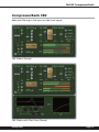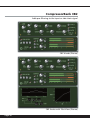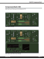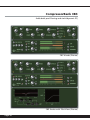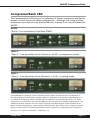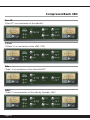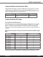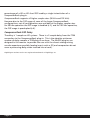
1
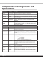
CompressorBank Configurations and
Specifications
Parameter
Settings
Function
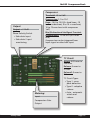
OUTPUT
-24 to +24 dB
Amount of make-up gain applied to master signal.
LOCK
ON/OFF
Locks right and left OUTPUT controls (stereo configurations only)
ø (PHASE)
ON/OFF
Polarity (phase) of the final output. When yellow LED is lit, signal
is 180 from original.
KEY
ENGAGED/
DISENGAGED
Selects the side chain signal to cause the Compressor to begin
reducing signal dynamics range once it exceeds the selected
threshold.
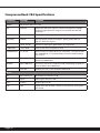
INPUT or
Output
METERs
-60 to 0 dB
Output level of band. Meters below COMPRESSION GAIN METER,
displayed in green and reading from left to right. Red LED’s are lit
to indicate output has clipped. Click LED to clear. Selected in the
Master Section “METERS”
IN
ON/OFF
Compressor enable/disable. Red LED is lit when band is enabled.
Threshold
- 45 to 0 dB
Level at which the compression starts. Also indicated by orange
triangle on OUTPUT METER.
Compression
10:1 to 1:1
Ratio of input to output levels for compressor. As input exceeds
the THRESHOLD, it is compressed by an amount determined by this
control.
Knee
-10.0 to 15.0
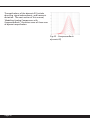
The smoothing of the compression response immediately below
and above the threshold level. See COMPRESSION DISPLAY for
visual display of differences.
-10 to 0 = undershoot
0 = hard knee
0 to 10 = overshoot
10 to 15 = overshoot with compressor ‘tail’
Bite
1.0 to 50.0
Bi-Directional Intelligent Transient Enhancement. As this control
is increased, fast signal changes (transients) are allowed to pass
through the compressor while the overall compression remains
the same.
Attack
0.03 to 250
msec
The rate at which the compressor responds to signals as they rise
above the THRESHOLD.
Release
5.0 msec to
2.5 sec
The rate at which the compressor stops responding to signals as
they fall below the THRESHOLD.
AUTO
ON/OFF
Automatic ATTACK and RELEASE. When AUTO mode is enabled,
Yellow LED is lit and ATTACK, RELEASE, and RELEASE2 controls are
disabled.
Compressor
Page 50