1
USBCNC
Manual
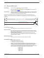
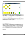
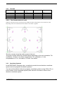
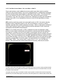
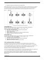
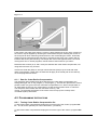
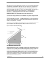
(DA in the figure) to divide the area outside the material near A into two regions; DA extended
is the dotted line AC on the figure. Make a pre-entry move to anywhere in the region on the
same side of DC as the remaining material (point B on the figure) and not so close to the
remaining material that the tool is cutting into it. Anywhere in the diagonally shaded area of
the figure (or above or to the left of that area) is OK. If the tool is already in region, no preentry move is needed. Write a line of NC code to move to B, if necessary. Then write a line of
NC code for a straight entry move that turns compensation on and goes to point A.
If B is at (1.5, 4), the two lines of code for the pre-entry and entry moves would be:
N0010 G1 X1.5 Y4 (move to B)
N0020 G41 G1 X3 Y3 (turn compensation on and make entry move to A)
These two lines would be followed by four lines identical to lines N0050 to N0080 from Table
A-1, but the end of the program would be different since the shape of remaining material is
different.
It would be OK for B to be on line AC. In fact, B could be placed on the extension outside the
part of any straight side of the part. B could be placed on EF extended to the right (but not to
the left, for going clockwise), for example.
If DA were an arc, not a straight line, the two lines of code above would still be suitable. In this
case, the dotted line extending DA should be tangent to DA at A.
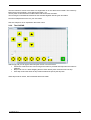
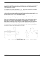
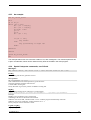
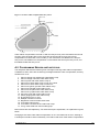
Figure A-3 Simpler cutter radius compensation entry move (for material edge contour)
Figure A-3 Simpler compensation entry move
A.4 NOMINAL PATH CONTOUR
When the contour is a nominal path contour (the path a tool with exactly the intended
diameter would take), the tool path is described in the NC program. It is expected that (except
for during the entry moves) the path is intended to create some part geometry. The path may
be generated manually or by a post-processor, considering the part geometry which is
intended to be made. For the Interpreter to work, the tool path must be such that the tool
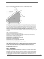
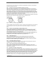
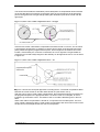
stays in contact with the edge of the part geometry, as shown on the left side of Figure A-1. If
a path of the sort shown on the right of Figure A-1 is used, in which the tool does not stay in
contact with the part geometry all the time, the Interpreter will not be able to compensate
properly when undersized tools are used. A nominal path contour has no corners, so the
simple method just described will not work.
27 March 2011
Release 3.50.5
108