1
LSS-100P
Installation and Operation Manual
181 Bonetti Dr San Luis Obispo CA 93401 USA
+1 805-549-0161 Office +1 805-549-0163 Fax
LSS−100P Installation & Operation Manual
Table of Contents
Introduction .......................................................................................................................... 3
Features ................................................................................................................................ 4
Initial Test and Configuration ................................................................................................. 6
Installation .............................................................................................................................................. 10
NTP, IR, and Luminance Check ................................................................................................................ 11
Script and DCP Test Run .......................................................................................................................... 12
Data Analysis....................................................................................................................... 13
CSV Data Use ........................................................................................................................................... 13
Multiple Logs on One Page ..................................................................................................................... 15
Multiple Auditorium Summary ............................................................................................................... 16
TCP Based Operations ......................................................................................................... 16
Log Post XML Format .............................................................................................................................. 19
Hidden Screens.................................................................................................................... 25
View Configuration Data ......................................................................................................................... 25
Calibration Screens ................................................................................................................................. 25
Firmware Update ................................................................................................................ 27
Restore Button ........................................................................................................................................ 27
Useful Software ................................................................................................................... 28
Product Support .................................................................................................................. 29
Warranty ................................................................................................................................................. 29
2
LSS−100P Installation & Operation Manual
Introduction
The LSS-100P is designed for cinema auditorium quality control. It measures C-weighted sound pressure
level (SPL) in dB, luminance in cd/m2 and fL, chromaticity (x and y), and correlated color temperature.
The LSS-100P makes all of these measurements available on a web interface, through TCP commands
over Ethernet, and by posting data to a remote web server for further analysis and display.
In a typical installation, the digital cinema server runs a test DCP each day. A cue in the show play list
tells the LSS-100P to start running a script that captures measured data at appropriate times in the DCP
play out. These values are limit checked, logged, and optionally posted to a remote web server for
further analysis.
The LSS-100P contains a color sensor, not an image sensor. There is no possibility of the LSS-100P
transmitting an image of the movie, so it does not present any security issues.
The LSS-100P can be powered by either the included USB power supply or by a Power Over Ethernet
enabled Ethernet switch or Power Injector.
The LSS-100P should be mounted on the rear wall of the auditorium. It is aimed towards the center of
the screen using the internal LEDs. Before the first show or after the last show, a test pattern is
projected and pink noise sent to each speaker. The LSS-100P measures the color, luminance, and SPL.
These measurements are used to identify lamps nearing end of life, misadjusted lamps, projector color
problems, defective speakers, etc.
Since measurements vary in different positions in the room, the measurements from the LSS-100P
should be compared with previous measurements to detect changes rather than interpreting the
absolute values delivered by the LSS-100P.
LSS-100P Package Contents
1
LSS-100P Unit
1
Power Supply / USB Charger
1
Power Cable 30’ USB
1
Wall / Ceiling Mount
1
USB To Terminal Adapter
1
LSS-100P User Manual
3
LSS−100P Installation & Operation Manual
Features
Luminance Measurement – Uses a precision detector with a photopic spectral response.
Chromaticity Measurement – Uses a precision RGB sensor and calculates XYZ, xy, and CCT.
SPL Measurement – Uses a DSP generated C-weighting filter and RMS detector for accurate
results regardless of signal waveform or crest factor.
IR Measurement – Measures relative IR illumination of screen to detect issues with IR emitters
used for hearing impaired audio, visually impaired audio, or closed captions.
Temperature Measurement – Includes an internal temperature sensor that can be used to
approximate auditorium temperature and track changes.
Web Interface – Displays live measured data along with user defined reference values.
TCP Command Interpreter – Accepts commands over Ethernet to log data, send current
measurement, start a measurement script, etc.
Command Scripting – An unlimited number of user scripts (up to a total of 64,530 characters)
may be defined. Scripting allows a test sequence to be started by sending only one command to
the LSS-100P.
Script Start with Contact Closure – Terminals are provided on the USB power interface board to
start three individual scripts with contact closures. This allows digital cinema servers without
provision for user defined TCP command strings to start LSS-100P scripts.
Logging with Limit Checking and Graph Generation – The LSS-100P can capture measurements
to a log. The log shows the measurement in red if it is outside user defined limits. The log can be
downloaded as a CSV file for analysis in a spreadsheet. The LSS-100P generates graphs of logged
data showing trends of the measured data along with limit lines.
Web Services Posting – The LSS-100P can post log data to one or more HTTP or HTTPS servers.
Log data is sent as XML for simple parsing into a database for report generation.
Power Over Ethernet – The LSS-100P can be powered by a POE enabled Ethernet switch or
power injector. Use of POE simplifies installation since fewer wires need to be run. The LSS-100P
is an IEEE 802.3af class 1 powered device. It may be powered by “active” (power sources that
use the POE signature) or “passive” (power sources that do not use the standard POE signature)
48V POE injectors. The LSS-100P consumes less than 1.5W.
USB Power – The LSS-100P can be powered by the supplied USB power supply. This is a low cost
alternative to POE.
4
LSS−100P Installation & Operation Manual
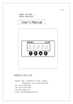
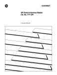
Figure 1- LSS-100P Home Page
Figure 2 - LSS-100P Log
5
LSS−100P Installation & Operation Manual
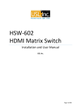
Figure 3 - LSS-100P Graph
Initial Test and Configuration
It is a lot easier to do the initial testing of the LSS-100P on a table or the floor of the projection booth
instead of on top of a ladder.
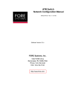
1. Connect power to the LSS-100P. This can be done using a standard USB to mini-USB cable and
the included USB power supply. A standard cable can also be used to power the LSS-100P from a
USB jack on a computer. If such a cable is not available, connect the supplied USB cable to the
supplied adapter board as shown in figures 4 and 5 (different cables use different colors).
Terminal
+5V
A
B
C
Ground
Wire Color
Red
Blue
Yellow
none
Black
Wire Color
Red
White
Green
none
Black
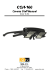
Figure 4 - USB Adapter Pin-Out
Figure 5 - USB Adapter Wiring
Note orientation of adapter in USB power supply (terminals down).
2. The green LED next to the Ethernet connector on the LSS-100P will light dimly for 30 seconds,
then light brightly. During this time, the LSS-100P is checking its backup copy of the system
firmware. The green LED is lit whenever the LSS-100P is powered unless the flash memory chip
6
LSS−100P Installation & Operation Manual
is being accessed (such as during the firmware check, loading or saving of configuration
information, etc.).
3. Connect an Ethernet cable between the LSS-100P and a laptop computer. Open a web browser
and type http://169.254.1.6 in the address bar. On most laptops, this will bring up the home
page of the LSS-100P. If it does not, try changing the laptop’s IP address to 169.254.1.123 with a
subnet mask of 255.255.0.0. Most laptops have automatic crossover for Ethernet, but some
older ones do not. If the LSS-100P home page is still not visible, try using an Ethernet crossover
cable between the laptop and the LSS-100P. The LSS-100P home page is shown below.
Figure 6 - LSS-100P Home Page
4. Click on the “config” to go to the Configuration Page. The username is “admin” and the
password is “ultra”. There are several configuration pages that are described below.
Figure 7 - LSS-100P Web Display Configuration Page.
7
LSS−100P Installation & Operation Manual
5. The first configuration page, shown above, allows you to determine how the home page will
appear. The Light Table section determines how the left side of the home page will appear (the
side that is showing luminance, color, etc.). The home page can show up to 7 rows of light
information. The source of that information is set by the first column of the light table. You can
select U.S. or metric units for temperature and luminance. LSS-100P units with board revision F
or higher also measure the relative IR illumination of the screen. This is useful for detecting
issues with IR audio and captioning systems. Select the data source for each line of the home
page light display.
6. Set the name for each line of the home page light display. These may be in any language.
7. The light table of the home page supports a total of 7 data columns. The first column is always
the current “live” measurement data. Additonal columns hold reference measurements. Live
data is copied to the reference measurement column by clicking on the header of the column on
the home page. Define a name for each of the data columns, The first column is always labeled
LIVE.
8. The right side of this configuration screen allows reference column names to be defined for the
SPL measurement. These behave the same as the light reference measurements described in
the previous step.
9. The LSS-100P determines the highest SPL it measured from midnight local time to midnight local
time. The highest value is logged each night at midnight. You can set a limit for the maximum
SPL on this page. If this value is exceeded, the maximum SPL of the day will be shown in red on
the log.
10. Once this data has been entered, click the “Save User Data” button to save the settings to the
LSS-100P.
11. Click the “Auditorium Data” link at the top of the page.
Figure 8 - LSS-100P Auditorium Data
12. Enter the theater name, theater number (large groups often identify a particular theater by
number), and the screen or auditorium number. Additional information about the auditorium
can be entered in the Comments field. These comments show up on the home page and are
reported in the XML web services log data. Click the “Save Auditorium Data” button to save the
data. Ignore the luminance scaling and IR Calibrate sections for now.
13. Click the Web Configuration link at the top of the page.
8
LSS−100P Installation & Operation Manual
Figure 9 - LSS-100P Web Configuration
14. Enter the host name (NET BIOS host name), IP address, gateway, subnet mask, and DNS
information. DNS is used if the NTP server or web services server is specified by a host name
instead of an IP address. If IP addresses are used instead of host names, these fields can be left
at 0.0.0.0. The default 8.8.8.8 is a DNS service provided by Google. After the network
information has been entered, click the “Save Config” button to save the settings. Note that the
new IP address takes effect immediately, so it will be necessary to address the LSS-100P at its
new address and will probably be necessary to change the laptop computer’s IP address to an
address on the same subnet.
15. Click the NTP Configuration link at the top of the page.
Figure 10 - LSS-100P NTP Configuration
16. An NTP server is required for the LSS-100P logging. Most digital cinema servers have an NTP
server in them, so the IP address of that server can be entered. If outgoing internet access is
available, the default setting of pool.ntp.org can be used. The NTP server IP address can be
entered as a dotted decimal IP address. If a DNS server was set up on the Web Configuration
screen, a domain name (such as pool.ntp.org) can be used instead.
17. Set the time zone UTC offset. Offsets for U.S. time zones are shown in figure 11. Note that
fractions of an hour can be set (required for Venezuela, Afghanistan, India, Sri Lanka, Nepal, and
other countries). Note that this is the offset for standard time, not advanced time, summer time,
or daylight saving time. Additional time zone information is available at
http://www.timeanddate.com/library/abbreviations/timezones/ and
http://en.wikipedia.org/wiki/List_of_time_zones_by_UTC_offset .
US Time Zone
UTC Offset
Standard Time Abbreviation
Daylight Saving Time Abbreviation
Hawaii-Aleutian
Alaska
Pacific
Mountain
Central
Eastern
-10.0
-9.0
-8.0
-7.0
-6.0
-5.0
HAST
AKST
PST
MST
CST
EST
HADT
AKDT
PDT
MDT
CDT
EDT
Figure 11 - U.S. Time Zone Offsets
9
LSS−100P Installation & Operation Manual
18. Enter the abbreviations for standard and advanced, summer, or daylight saving time. Select
whether daylight saving (or similar) is observed at the location the LSS-100P is installed. This
setting is not whether DST is currently being observed, but whether it is ever observed. For
example, in the U.S., this would be set to “no” for Arizona and “yes” for California. The LSS-100P
displayed logs will take this into consideration when displaying the time at the LSS-100P.
19. Note that the bottom line of this page shows the last time the LSS-100P clock was updated from
the NTP server. Since the LSS-100P does not have access to an NTP server when it is only
connected to your laptop, this will indicate that the last update was never.
Installation
1. Use the supplied OmniMount 10.0 wall mount to attach the LSS-100P to the auditorium back
wall. Aim the lens and microphone towards the screen. Thread the supplied nut onto the
OmniMount threaded rod with the flat side of the nut towards the threaded end and away from
the ball. Thread the OmniMount threaded rod into the threaded hole on the LSS-100P turning
the LSS-100P four turns, adjusting a fraction of a turn as required to point the LSS-100P towards
the screen. Tighten the nut on the threaded rod against the LSS-100P case to firmly mount the
LSS-100P to the threaded rod.
2. If necessary, drill a hole between the booth and auditorium for the wiring. If the LSS-100P will be
powered by Power Over Ethernet and will not use contact closure triggering, only the Ethernet
cable needs to be installed. If USB power or contact closure triggering is to be used, route the
included USB cable from the LSS-100P through the wall along with the Ethernet cable.
3. Connect the Ethernet cable to the LSS-100P and the auditorium Ethernet switch.
4. If USB power or contact closure script triggering is being used, connect the supplied cable to the
LSS-100P. Connect the other end of the cable to the USB adapter board. Refer to Figures 4 and 5
for wiring instructions. If contact closure script triggering is being used with Power Over
Ethernet, the USB cable can be routed directly to the GPIO connections on the server. Refer to
figure 4 for wire colors.
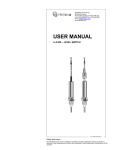
5. If contact closure script triggering is to be used, connect the contact closures from the digital
cinema server to the USB adapter board as shown in Figure 12. Pulses should be about 500ms
long.
Pulse to ground
A
B
C
To Start Script
0
1
2
Figure 12 - LSS-100P USB Adapter to Cinema Server GPIO Wiring
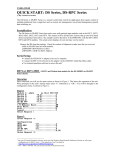
6. Turn the LSS-100P LED switch to on and adjust the focus control until the red spots on the
screen appear to be in focus. As the LSS-100P is adjusted out of focus, the hole in the middle of
the spots fills in. When the LSS-100P is in focus, the hole in the center will be open and the
edges sharp as shown in Figure 13. Once focus is set, lock the lens position by tightening the
thumb screw on the lens tube.
7. Project the test pattern on the screen. Suggested test content is the USL LST-100 DCP. It is
available from USL on a USB flash drive or can be downloaded from
http://ftp.uslinc.com/ftp/Products/LSS-100/Software/TestContent/lss_calibration_dcp_usl_130512.tar.gz .
Position the LED spots to be in the center of the test pattern area. Since the projector lamp is
much more powerful than the LEDs in the LSS-100P, it may be difficult to see the LED spots
when the test pattern is on. A simple method of seeing where the LED spots are within the test
pattern is to wave a hand through the projector beam, casting a shadow on the screen. As the
10
LSS−100P Installation & Operation Manual
shadow moves across the screen, the LED spots and their location within the test pattern will
become visible. The LSS-100P sensor is a linear sensor positioned midway between the LEDs. If
the test pattern is tall, adjust the LSS-100P to align the spots vertically. If the test pattern is
wide, rotate the LSS-100P to align the spots horizontally. Place the center of the area between
the spots in the center of the test pattern area. Lock the Omnimount position and turn off the
LEDs.
Figure 13 - LSS-100 LED Focus and aim.
8. Turn on a pink noise source on one of the auditorium speakers. The SPL indicated by the LSS100P should be close to that measured with an SPL meter. Again, due to system tolerances and
variations in sound level throughout the auditorium, the numbers will not match precisely.
NTP, IR, and Luminance Check
1. Go back to the NTP configuration page (shown in figure 10) and ensure that the LSS-100P has
received an NTP update.
2. If desired, the LSS-100P luminance measurement can be scaled to agree with a reference meter.
The LSS-100P is factory calibrated, but, because it is not in the same location as a reference
meter in the auditorium, it will probably read slightly different from the reference meter due to
screen gain, elevation of the projector above the screen center, etc. Project the test pattern
(ideally from the LST-100) and measure the luminance with the reference meter. While the test
pattern is still present, key the measured luminance value into the appropriate box (cd/m2 or fL)
in the Luminance Scaling section of the Auditorium Data page (see figure 8). Click the “Save
Settings” button to scale the LSS-100P luminance measurement to match the reference meter.
You can click the “Reset Luminance Scaling” button to return the LSS-100P to factory calibration.
3. IR Calibrate also appears on the Auditorium Data page (board revision F and higher). Press the
“Set IR Reference” button when typical IR illumination of the screen is present. When the LST100 test content plays, a USL UPC-28C emitter transmits the hearing impaired and closed
caption carriers, but not the visually impaired carrier. If you click the “Set IR Reference” button
when the LST-100 content is playing, the LSS-100P will set this level to 100%. The LSS-100P will
read about 75% if only one IR carrier is present. It will read about 117% if all 3 carriers are
present.
11
LSS−100P Installation & Operation Manual
Script and DCP Test Run
The LSS-100P is shipped with scripts for use with the LST-100 DCP. This section covers running the test
DCP and configuring limits on the scripts.
1. Create a show to play the LST-100 DCP on the digital cinema server.
2. If the server supports user-defined cues over Ethernet, instruct the server to send this command
when the DCP starts: lss100.sys.script_run
3. The text should be terminated with a carriage return (0x0d or \r).
4. If the server does not support user-defined cues over Ethernet, define a cue at the start of the
DCP playout to pulse (500ms) a contact closure between terminals A and ground on the USB
adapter board. This contact closure or the Ethernet command causes the LSS-100P to start
executing script 0 (the first script).
5. Add appropriate cues to the playlist to set the sound processor at reference level (0.0dB or 7.0)
and take audio from the digital cinema server, turn on the projector lamp, open the dowser,
turn off the house lights, etc.
6. Run the test show. When it is complete, verify that data has been saved in the log. Print the log
for reference in the next few steps.
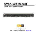
7. Click the “Command Scripts” link at the top of the configuration page. A page similar to Figure
14 should appear. Lines starting with # are comments and are ignored. Blank lines separate
scripts. The first script is script 0. There’s a blank line at the end of script 0. The next line is the
start of script 1. Only insert one (not more) blank lines between scripts. There should be nothing
on the blank lines between scripts (not even space characters). Fields are delimited with the
pipe character (|). The various capture commands have these fields:
a) The command (“lss100.sys.capture_spl”).
b) A user defined description of what is being measured (“Left Low”).
c) A minimum limit (“75”).
d) A maximum limit (“85”).
8. Based on the test run of the show, adjust the minimum and maximum values for each
measurement. The measured SPL values will vary as different bands and different speakers are
run. We suggest setting limits 3dB below and above the values measured on the test show.
Failures in the audio equipment will result in values outside this range. Note that the limits set
for luminance and chromaticity are based on SMPTE standards and should not require
adjustment. Note that the description portion of each line of the script is user definable.
Descriptions in other languages may be substituted, if desired. These descriptions will be used
in the LSS-100P internal log, graphing, and web services reporting. If there are no limits on a
measurement, leave the minimum and maximum out (end the line after the description).
Internally and in web services reporting, a log record with no limits has its minimum set to -9e9
and its maximum set to +9e9.
9. If web services reporting is desired, put the URL of the server in the lss100.sys.log_post line. For
example, “lss100.sys.log_post|http://lss.uslinc.com/xml/post.php” posts the log to the USL LSS
server. The URL can be either HTTP or HTTPS. It cannot include a port number (the server must
accept posts on the default HTTP and HTTPS ports).
12
LSS−100P Installation & Operation Manual
Figure 14 - LSS-100P Command Script Page
10. Click the “Save Script” button to save the revised script.
11. Run the test show a couple times and review the log. It should appear similar to figure 2 but
with the latest values not in red. Measured values that are not between the specified minimum
and maximum are shown in red.
12. Click on a value in the log. A graph of the measured values (similar to figure 3 but with fewer
values) should appear. If the test script has only run once, no graph will appear. At least two
measurements are required to draw the graph.
Data Analysis
The LSS-100P presents the captured data in a log (as shown in figure 2) and a graph (as shown in figure
3). Out of limit operation is easily identified in the log by a value being printed in red. The graphs show
the measured values along with limit lines allowing easy detection of trends and out of limit operation.
Log data is also available as a Comma Separated Value file for analysis in a spreadsheet. Click the CSV
link at the bottom of a log page to get the CSV log.
Log data can also be posted to a web server as XML for further analysis and consolidation with data from
other sites.
CSV Data Use
Click CSV to download the log as a comma separated value file for importing the data into a
spreadsheet. A portion of a typical download is shown below.
13
LSS−100P Installation & Operation Manual
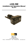
Figure 15 - LSS-100P CSV Data
Change the format of column C (LSS Time) to date. The result is shown below:
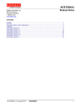
Figure 16 - LSS-100P CSV with Local Time Converted
Sort the spreadsheet on column D (description) to gather like readings together. Graphing or analysis
can then be easily accomplished. The image below shows the generation of a plot of the SPL from the
center channel mid-band measurements.
Figure 17 – Graph Generation from LSS-100P CSV Data
14
LSS−100P Installation & Operation Manual
Multiple Logs on One Page
It may be desirable to have a single web page that includes the logs from multiple LSS-100P units (for
example, all the auditoriums in a particular theater). This can be accomplished using HTML iframes
(inline frames). Sample code to include multiple LSS-100P log pages is shown below. This code can be
placed on the computer the browser is running on or on a local web server.
<!doctype html>
<html>
<head>
<title>Obispo LSS-100 Summary</title>
</head>
<body>
<h1 align=”center”>Obispo LSS-100 Summary</title
<iframe seamless frameborder="0" src="http://192.168.6.55/log.cgi?n=20&GuiTz=25200&GuiTzName=Pacific%20Standard%20Time&DST=1" width="100%"
height="700"></iframe><br />
<iframe seamless frameborder="0" src="http://192.168.6.110/log.cgi?n=20&GuiTz=25200&GuiTzName=Pacific%20Standard%20Time&DST=1" width="100%" height="700"></iframe>
</body>
</html>
The iframe does a “client side include” of multiple web pages. The attributes of the iframe tag are
described below.
The seamless and frameborder=”0” attributes merge the fetched log pages into the resulting page with
no frame borders so it appears to be one page.
The src attribute contains the URL of the log to be inserted at this point. It is simplest to connect to the
LSS-100P home page, click log, then copy the resulting URL for use here with the changes listed below.
Delete the “rn=xx&” from the URL. rn holds the first record number to be displayed. The next part of the
URL (“n=100”) indicates how many records will be shown. If rn is deleted, the LSS-100P shows the n
most recent records. By deleting rn from the URL in the iframe, your page will always show the most
recent log entries.
Change “n=100” to “n=20” or some other number indicating the number of log entries you want shown
on this combined log page. If you do a daily log review, you may want to show three days worth of log
entries to ensure data from weekends is reviewed.
GuiTz can generally remain unchanged. It is the offset in seconds from UTC where the browser is
located. Similarly, the GuiTzName can remain unchanged. You may need to change DST between 1 and 0
depending on whether daylight saving time is currently in effect. You could build two pages (one for DST
and one for standard time) or include the javascript at the top of the LSS-100P home page that
determines whether DST is in effect at the GUI.
The width attribute is set to 100% so the iframe consumes 100% of the width of the browser window.
The height is specified in pixels. If this is too small, scroll bars will appear on the resulting web page for
each of the iframes. Making it too large results in empty space on the page. Experiment with this until
you get the look you want for multiple logs on a single web page.
15
LSS−100P Installation & Operation Manual
Multiple Auditorium Summary
Another method of presenting multiple auditoriums on a single web page is to build a list of links to the
auditoriums. The LSS-100P automatically supplies a link to a log that includes the theater name and the
screen number. If there is an out of limits log entry in the log record range specified, the log link appears
in red. You don’t have to look at logs from auditoriums where all is well. Sample HTML is shown below.
<!doctype html>
<html>
<head>
<title>Obispo LSS-100 Summary</title>
</head>
<body>
<h1 align=”center”>Obispo LSS-100 Summary</title>
<iframe seamless frameborder="0" src="http://192.168.6.55/loglink.cgi?n=20&GuiTz=25200&GuiTzName=Pacific%20Standard%20Time&DST=1" width="100%" height="50"></iframe><br
/>
<iframe seamless frameborder="0" src="http://192.168.6.110/loglink.cgi?n=20&GuiTz=25200&GuiTzName=Pacific%20Standard%20Time&DST=1" width="100%" height="50"></iframe>
Most of the iframe attributes are similar to the previous example. As noted before, the lack of an rn in
the src attribute tells the LSS-100P to evaluate the last n records for an out of limit condition. In the
examples above, a particular log link will be red if one of the last 20 records shows an out of limits
condition.
The image below shows how the HTML above appears in our test system:
Figure 18 - LSS-100P Multiple Auditorium Links
TCP Based Operations
The LSS-100P uses TCP port 10001. It can accept 5 simultaneous TCP connections. Commands are lower
case and terminated with a carriage return (0x0d). Parameters, if any, are separated by tab characters
(0x09) or a pipe character (|). Responses are in ASCII and terminated with a carriage return. If multiple
values are returned, they are separated with tab characters. In some cases, there may be a tab character
after the last response and before the carriage return. The command is not echoed by the LSS-100P.
LSS-100P commands can be tested using Tera Term, RealTerm (both listed below), or telnet on
operating systems that include it (Windows XP, Linux, Mac OS). Since the LSS-100P does not echo
commands or append line feed characters, Tera Term and similar programs should be set for local echo
and CR+LF on receiving a carriage return. These options are in the Setup – Terminal menu on Tera Term.
16
LSS−100P Installation & Operation Manual
The LSS-100P commands and typical responses are shown in figure 19. Note that many of these
commands are commonly used in scripts (described previously), and the lss100.sys.script_run command
can be used to start script execution.
Command
lss100.sys.auditorium
lss100.sys.cct
lss100.sys.cdm2
lss100.sys.comments
lss100.sys.ftl
lss100.sys.spl
lss100.sys.temperature
lss100.sys.theater_name
lss100.sys.theater_number
lss100.sys.ver
lss100.sys.xy
lss100.sys.capture_spl|SPL Center Low|81.2|83.2
lss100.sys.capture_fl|Luminance|13|15
lss100.sys.capture_cdm2|Luminance|47|49
Response
1
Description
Returns the auditorium number
entered on the configuration
page.
6255.250284
Returns the correlated color
temperature.
405.151492
Returns the luminance in
candelas per square meter
Conference Room
Returns the auditorium
comments entered on the
configuration page.
118.332596
Returns the measured luminance
in foot-Lamberts
83.239520
Returns the measured sound
pressure level in dBc
29.2\t84.
Returns the internal
temperature in degrees C and
degrees F (separated by tab).
USL San Luis Obispo Returns the theater name
entered on the configuration
page.
1
Returns the theater number
entered on the configuration
page.
C\t130522\t120530 Returns the circuit board
version, the firmware version,
and the bootloader versions,
separated by tab.
0.314743\t0.353419 Returns the chromaticity as x tab
y.
83.239520
Instructs the LSS-100P to capture
the current SPL to its log. The
parameters are description, min,
and max. Returns the current
SPL in dBc.
14.1234
Instructs the LSS-100P to capture
the luminance (measured in fL)
to its log. The parameters are
description, min, and max.
48.4321
Instructs the LSS-100P to capture
the luminance (measured in
cd/m2) to its log. The parameters
are description, min, and max.
17
LSS−100P Installation & Operation Manual
lss100.sys.capture_cct|Color Temperature|6100|6300
6262
lss100.sys.capture_temperature_c|Temperature|20|40 25
lss100.sys.capture_temperature_f|Temperature|60|80
70
lss100.sys.capture_x|Color|0.308|0.320
0.314
lss100.sys.capture_y|Color|0.345|0.357
0.351
lss100.sys.log_post|http://lss.uslinc.com/xml/post.php
lss100.sys.script_run|0
lss100.sys.script_wait|30
Instructs the LSS-100P to capture
the correlated color temperature
in Kelvin to its log. The
parameters are description, min,
and max
Instructs the LSS-100P to capture
its internal temperature in
Celcius to its log. The parameters
are description, min, and max.
Instructs the LSS-100P to capture
its internal temperature in
Fahrenheit to its log. The
parameters are description, min,
and max.
Instructs the LSS-100P to capture
the color coordinate x. The
parameters are description,
Xmin, Xmax.
Instructs the LSS-100P to capture
the color coordinate y. The
parameters are description,
Ymin, Ymax.
Posts logs in XML to the specified
URL. The URL can be HTTP or
HTTPS. No port numbers are
allowed. Posts all log data since
the last log post to this URL. If
more than one post is included
in a script, add a wait of 60
seconds between posts to allow
time for the first to complete.
Runs the specified script. If no
script number is specified, runs
script 0 (the first one).
Causes a script to wait the
specified number of seconds
before executing the next line.
Waits between captures keeps
the measurement capture
synchronized with the test
content.
Figure 19 - LSS-100P TCP Commands
18
LSS−100P Installation & Operation Manual
Log Post XML Format
Sample XML data posted to a web server is shown below. Note that the web server must accept
chunked data as defined in RFC 2616 section 3.6.1. Note that DateTime is a Unix time stamp (seconds
since January 1, 1970 UTC).
<?xml version="1.0" encoding="UTF-8"?>
<LssLogPost>
<Record>
<RecordNum>19</RecordNum>
<DateTime>956</DateTime>
<Description>Silence</Description>
<Value>58.9</Value>
<Units>dBc</Units>
<Minimum>50</Minimum>
<Maximum>60</Maximum>
<OutsideLimits>0</OutsideLimits>
<SerialNumber>0157</SerialNumber>
<TheaterName>Obispo</TheaterName>
<TheaterNumber></TheaterNumber>
<AuditoriumNumber>1</AuditoriumNumber>
<Comments>HW Rev F</Comments>
<Firmware>140530</Firmware>
<Hardware>F</Hardware>
<IpAddress>192.168.1.153</IpAddress>
</Record>
<Record>
<RecordNum>20</RecordNum>
<DateTime>986</DateTime>
<Description>SPL Left Low</Description>
<Value>87.3</Value>
<Units>dBc</Units>
<Minimum>82.7</Minimum>
<Maximum>88.7</Maximum>
<OutsideLimits>0</OutsideLimits>
<SerialNumber>0157</SerialNumber>
<TheaterName>Obispo</TheaterName>
<TheaterNumber></TheaterNumber>
<AuditoriumNumber>1</AuditoriumNumber>
<Comments>HW Rev F</Comments>
<Firmware>140530</Firmware>
<Hardware>F</Hardware>
<IpAddress>192.168.1.153</IpAddress>
</Record>
<Record>
<RecordNum>21</RecordNum>
<DateTime>1016</DateTime>
<Description>SPL Left Mid</Description>
<Value>74.1</Value>
<Units>dBc</Units>
<Minimum>70.5</Minimum>
<Maximum>76.5</Maximum>
<OutsideLimits>0</OutsideLimits>
<SerialNumber>0157</SerialNumber>
19
LSS−100P Installation & Operation Manual
<TheaterName>Obispo</TheaterName>
<TheaterNumber></TheaterNumber>
<AuditoriumNumber>1</AuditoriumNumber>
<Comments>HW Rev F</Comments>
<Firmware>140530</Firmware>
<Hardware>F</Hardware>
<IpAddress>192.168.1.153</IpAddress>
</Record>
<Record>
<RecordNum>22</RecordNum>
<DateTime>1035</DateTime>
<Description>Max SPL of day</Description> <Value>76.4</Value> <Units>dBc</Units>
<Minimum>0</Minimum> <Maximum>100</Maximum> <OutsideLimits>0</OutsideLimits>
<SerialNumber>0157</SerialNumber> <TheaterName>Obispo</TheaterName>
<TheaterNumber></TheaterNumber> <AuditoriumNumber>1</AuditoriumNumber>
<Comments>HW Rev F</Comments>
<Firmware>140530</Firmware>
<Hardware>F</Hardware>
<IpAddress>192.168.1.153</IpAddress>
</Record>
<Record>
<RecordNum>23</RecordNum>
<DateTime>1401738876</DateTime>
<Description>SPL Left High</Description> <Value>76.3</Value> <Units>dBc</Units>
<Minimum>73.9</Minimum> <Maximum>79.9</Maximum> <OutsideLimits>0</OutsideLimits>
<SerialNumber>0157</SerialNumber> <TheaterName>Obispo</TheaterName>
<TheaterNumber></TheaterNumber> <AuditoriumNumber>1</AuditoriumNumber>
<Comments>HW Rev F</Comments>
<Firmware>140530</Firmware>
<Hardware>F</Hardware>
<IpAddress>192.168.1.153</IpAddress>
</Record>
<Record>
<RecordNum>24</RecordNum>
<DateTime>1401738906</DateTime>
<Description>SPL Right Low</Description> <Value>84.8</Value> <Units>dBc</Units>
<Minimum>80.7</Minimum> <Maximum>86.7</Maximum> <OutsideLimits>0</OutsideLimits>
<SerialNumber>0157</SerialNumber> <TheaterName>Obispo</TheaterName>
<TheaterNumber></TheaterNumber> <AuditoriumNumber>1</AuditoriumNumber>
<Comments>HW Rev F</Comments>
<Firmware>140530</Firmware>
<Hardware>F</Hardware>
<IpAddress>192.168.1.153</IpAddress>
</Record>
<Record>
<RecordNum>25</RecordNum>
<DateTime>1401738936</DateTime>
<Description>SPL Right Mid</Description> <Value>77.2</Value> <Units>dBc</Units>
<Minimum>74.1</Minimum> <Maximum>80.1</Maximum> <OutsideLimits>0</OutsideLimits>
<SerialNumber>0157</SerialNumber> <TheaterName>Obispo</TheaterName>
<TheaterNumber></TheaterNumber> <AuditoriumNumber>1</AuditoriumNumber>
<Comments>HW Rev F</Comments>
<Firmware>140530</Firmware>
<Hardware>F</Hardware>
20
LSS−100P Installation & Operation Manual
<IpAddress>192.168.1.153</IpAddress>
</Record>
<Record>
<RecordNum>26</RecordNum>
<DateTime>1401738966</DateTime>
<Description>SPL Right High</Description> <Value>80</Value> <Units>dBc</Units>
<Minimum>76.7</Minimum> <Maximum>82.7</Maximum> <OutsideLimits>0</OutsideLimits>
<SerialNumber>0157</SerialNumber> <TheaterName>Obispo</TheaterName>
<TheaterNumber></TheaterNumber> <AuditoriumNumber>1</AuditoriumNumber>
<Comments>HW Rev F</Comments>
<Firmware>140530</Firmware>
<Hardware>F</Hardware>
<IpAddress>192.168.1.153</IpAddress>
</Record>
<Record>
<RecordNum>27</RecordNum>
<DateTime>1401738996</DateTime>
<Description>SPL Center Low</Description> <Value>81</Value> <Units>dBc</Units>
<Minimum>77.4</Minimum> <Maximum>83.4</Maximum> <OutsideLimits>0</OutsideLimits>
<SerialNumber>0157</SerialNumber> <TheaterName>Obispo</TheaterName>
<TheaterNumber></TheaterNumber> <AuditoriumNumber>1</AuditoriumNumber>
<Comments>HW Rev F</Comments>
<Firmware>140530</Firmware>
<Hardware>F</Hardware>
<IpAddress>192.168.1.153</IpAddress>
</Record>
<Record>
<RecordNum>28</RecordNum>
<DateTime>1401739026</DateTime>
<Description>SPL Center Mid</Description> <Value>73.8</Value> <Units>dBc</Units>
<Minimum>70.8</Minimum> <Maximum>76.8</Maximum> <OutsideLimits>0</OutsideLimits>
<SerialNumber>0157</SerialNumber> <TheaterName>Obispo</TheaterName>
<TheaterNumber></TheaterNumber> <AuditoriumNumber>1</AuditoriumNumber>
<Comments>HW Rev F</Comments>
<Firmware>140530</Firmware>
<Hardware>F</Hardware>
<IpAddress>192.168.1.153</IpAddress>
</Record>
<Record>
<RecordNum>29</RecordNum>
<DateTime>1401739056</DateTime>
<Description>SPL Center High</Description> <Value>75.6</Value> <Units>dBc</Units>
<Minimum>73.9</Minimum> <Maximum>79.9</Maximum> <OutsideLimits>0</OutsideLimits>
<SerialNumber>0157</SerialNumber> <TheaterName>Obispo</TheaterName>
<TheaterNumber></TheaterNumber> <AuditoriumNumber>1</AuditoriumNumber>
<Comments>HW Rev F</Comments>
<Firmware>140530</Firmware>
<Hardware>F</Hardware>
<IpAddress>192.168.1.153</IpAddress>
</Record>
<Record>
<RecordNum>30</RecordNum>
<DateTime>1401739086</DateTime>
<Description>SPL LFE</Description>
21
LSS−100P Installation & Operation Manual
<Value>85.3</Value>
<Units>dBc</Units>
<Minimum>80.8</Minimum>
<Maximum>86.8</Maximum>
<OutsideLimits>0</OutsideLimits>
<SerialNumber>0157</SerialNumber>
<TheaterName>Obispo</TheaterName>
<TheaterNumber></TheaterNumber>
<AuditoriumNumber>1</AuditoriumNumber>
<Comments>HW Rev F</Comments>
<Firmware>140530</Firmware>
<Hardware>F</Hardware>
<IpAddress>192.168.1.153</IpAddress>
</Record>
<Record>
<RecordNum>31</RecordNum>
<DateTime>1401739116</DateTime>
<Description>SPL Ls</Description>
<Value>85.4</Value>
<Units>dBc</Units>
<Minimum>80.9</Minimum>
<Maximum>86.9</Maximum>
<OutsideLimits>0</OutsideLimits>
<SerialNumber>0157</SerialNumber>
<TheaterName>Obispo</TheaterName>
<TheaterNumber></TheaterNumber>
<AuditoriumNumber>1</AuditoriumNumber>
<Comments>HW Rev F</Comments>
<Firmware>140530</Firmware>
<Hardware>F</Hardware>
<IpAddress>192.168.1.153</IpAddress>
</Record>
<Record>
<RecordNum>32</RecordNum>
<DateTime>1401739146</DateTime>
<Description>SPL Rs</Description>
<Value>84.9</Value>
<Units>dBc</Units>
<Minimum>81.3</Minimum>
<Maximum>87.3</Maximum>
<OutsideLimits>0</OutsideLimits>
<SerialNumber>0157</SerialNumber>
<TheaterName>Obispo</TheaterName>
<TheaterNumber></TheaterNumber>
<AuditoriumNumber>1</AuditoriumNumber>
<Comments>HW Rev F</Comments>
<Firmware>140530</Firmware>
<Hardware>F</Hardware>
<IpAddress>192.168.1.153</IpAddress>
</Record>
<Record>
<RecordNum>33</RecordNum>
<DateTime>1401739146</DateTime>
<Description>Luminance</Description>
22
LSS−100P Installation & Operation Manual
<Value>9.13</Value>
<Units>fL</Units>
<Minimum>11</Minimum>
<Maximum>17</Maximum>
<OutsideLimits>1</OutsideLimits>
<SerialNumber>0157</SerialNumber>
<TheaterName>Obispo</TheaterName>
<TheaterNumber></TheaterNumber>
<AuditoriumNumber>1</AuditoriumNumber>
<Comments>HW Rev F</Comments>
<Firmware>140530</Firmware>
<Hardware>F</Hardware>
<IpAddress>192.168.1.153</IpAddress>
</Record>
<Record>
<RecordNum>34</RecordNum>
<DateTime>1401739146</DateTime>
<Description>Color x</Description>
<Value>0.311</Value>
<Units>x</Units>
<Minimum>0.308</Minimum>
<Maximum>0.32</Maximum>
<OutsideLimits>0</OutsideLimits>
<SerialNumber>0157</SerialNumber>
<TheaterName>Obispo</TheaterName>
<TheaterNumber></TheaterNumber>
<AuditoriumNumber>1</AuditoriumNumber>
<Comments>HW Rev F</Comments>
<Firmware>140530</Firmware>
<Hardware>F</Hardware>
<IpAddress>192.168.1.153</IpAddress>
</Record>
<Record>
<RecordNum>35</RecordNum>
<DateTime>1401739146</DateTime>
<Description>Color y</Description>
<Value>0.348</Value>
<Units>y</Units>
<Minimum>0.345</Minimum>
<Maximum>0.357</Maximum>
<OutsideLimits>0</OutsideLimits>
<SerialNumber>0157</SerialNumber>
<TheaterName>Obispo</TheaterName>
<TheaterNumber></TheaterNumber>
<AuditoriumNumber>1</AuditoriumNumber>
<Comments>HW Rev F</Comments>
<Firmware>140530</Firmware>
<Hardware>F</Hardware>
<IpAddress>192.168.1.153</IpAddress>
</Record>
<Record>
<RecordNum>36</RecordNum>
<DateTime>1401739146</DateTime>
<Description>IR Level</Description>
23
LSS−100P Installation & Operation Manual
<Value>98.1</Value>
<Units>%</Units>
<Minimum>90</Minimum>
<Maximum>150</Maximum>
<OutsideLimits>0</OutsideLimits>
<SerialNumber>0157</SerialNumber>
<TheaterName>Obispo</TheaterName>
<TheaterNumber></TheaterNumber>
<AuditoriumNumber>1</AuditoriumNumber>
<Comments>HW Rev F</Comments>
<Firmware>140530</Firmware>
<Hardware>F</Hardware>
<IpAddress>192.168.1.153</IpAddress>
</Record>
<Record>
<RecordNum>37</RecordNum>
<DateTime>1401739149</DateTime>
<Description>Posted to http://lss.uslinc.com/xml/post.php</Description>
<Value>3.26e+03</Value>
<Units></Units>
<Minimum>-9e+09</Minimum>
<Maximum>9e+09</Maximum>
<OutsideLimits>0</OutsideLimits>
<SerialNumber>0157</SerialNumber>
<TheaterName>Obispo</TheaterName>
<TheaterNumber></TheaterNumber>
<AuditoriumNumber>1</AuditoriumNumber>
<Comments>HW Rev F</Comments>
<Firmware>140530</Firmware>
<Hardware>F</Hardware>
<IpAddress>192.168.1.153</IpAddress>
</Record>
</LssLogPost>
The web server can parse the XML to a database for further analysis and reporting. A simple PHP script
that appends each new LSS-100P XML report to a file and mails each report is shown below. This is a
good starting point to verify that things are working.
<?php
$PostData=file_get_contents("php://input"); // get post data into a string
file_put_contents("/tmp/PostTest.txt",$PostData,FILE_APPEND); // append post data to a
file
// Set up to mail data
$to='[email protected]';
$subject='LSS-100 Post Data';
$headers= 'From: [email protected]';
mail($to, $subject, $PostData, $headers);
?>
24
LSS−100P Installation & Operation Manual
Hidden Screens
The LSS-100P has a few hidden screens that are described below. One shows the configuration data for
the unit. The other two allow for calibration (or mis-calibration) of the unit.
View Configuration Data
The LSS-100P configuration is saved as text in a series of commands. These commands are sent through
the same command interpreter as commands received over TCP or from a script. You can view this data
at http://xxx.xxx.xxx.xxx/ConfigFlash.html (substituting the IP address of the LSS-100P for the xxx).
Calibration Screens
These screens are supplied to allow for field calibration of the LSS-100P. You should ONLY attempt this if
you have accurate reference instrumentation. Light calibration is to be done with a projector having the
same illumination source as will be used in operation. If a xenon projector is to be used, the LSS-100P
must be calibrated with a xenon source (ideally the same projector). Luminance and color MUST be
measured with a spectrometer-based instrument, such as the USL PCA-100. Reference measurements
should be made as close to the LSS-100P position as possible. Do not attempt calibration without the
appropriate equipment.
Two calibration screens are available:
http://xxx.xxx.xx.xx/protect/cal.html - Calibration using cd/m2.
http://xxx.xxx.xx.xx/protect/calf.html - Calibration using fL.
These screens are similar. A portion of the cal.html screen is shown in Figure 20.
Figure 20 - LSS-100P Calibration Screen
25
LSS−100P Installation & Operation Manual
Besides calibration, these screens includes factory configuration features and debug information.
The Copy PIC code to restore flash copies the currently loaded firmware to external flash as a backup.
The number to the left of this button is a count of how many bytes disagree. We recommend not
clicking this button in the field. Keeping the factory firmware as a backup allows you to go back to it
should something go wrong.
The Set Serial Number button is not normally used in the field. Besides setting the serial number of the
unit (which is used in determining the MAC address of the unit), this button writes a default script to the
system. This may be useful if a firmware update is done to a unit that did not previously have scripting.
Use the procedure below to calibrate the light and IR portion of the LSS-100P:
1. Present the LSS-100P with total darkness. This can be accomplished by putting a lens cap over
the lens or by dowsing the projector and removing power from any IR panels in the auditorium.
Once the LSS-100P is presented with total darkness, click the “Save Dark Count” button. This
sets a dark reference for both the luminance and IR sensors.
2. Project a full-screen red test pattern on the screen. Measure the color (x,y) and luminance with
the spectrometer-based reference meter. While the test pattern is still on the screen, key these
values in the “red” line of the calibration form, then click “Save Red Data.”
3. Project a full-screen white test pattern on the screen. Measure the color (x,y) and luminance
with the spectrometer-based reference meter. While the test pattern is still on the screen, key
these values in the “white” line of the calibration form, then click “Save White Data.”
4. Project a full-screen blue test pattern on the screen. Measure the color (x,y) and luminance with
the spectrometer-based reference meter. While the test pattern is still on the screen, key these
values in the “blue” line of the calibration form, then click “Save Blue Data.”
5. Click the “Calibrate Light Sensor” button.
To calibrate the SPL meter, drive the center speaker with pink noise at reference level (typically 85dBc).
Use an RMS-based SPL meter with slow response to measure the SPL at the LSS-100P. Key that value
into the “Measured SPL” field, then click the “Calibrate Microphone” button.
The remainder of the screen includes information to aid in the production test of the LSS-100P. It can be
ignored while doing field calibration of the LSS-100P.
26
LSS−100P Installation & Operation Manual
Firmware Update
USL may offer firmware updates to add features to the LSS-100P. Firmware updates are delivered as a
“hex” file. To install the update, click on “Update Firmware Page” on the “Configuration Page.” The
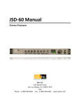
firmware update page is shown in Figure 21. Note that some firmware updates may result in a change in
log format. For this reason, this page includes a “Clear Log” button. This button can also be used to clear
the log for other reasons.
Figure 21 - LSS-100P firmware update page.
Follow these step-by-step instructions to do a firmware update:
1. Use the browse button to select the hex file to be loaded into the LSS-100P.
2. Press “Update Main Processor.” The green LED on the LSS-100P will flash as the new firmware is
installed. After the new code is uploaded to the LSS-100P, the browser will return a “Connection
Reset” message. This happens when the LSS-100P reboots with the new firmware.
If a firmware update is interrupted, it is possible for the LSS-100P to cease operating. To restore the
factory firmware (allowing another attempt at the update), hold down the restore button as power is
applied to the LSS-100P. If the button is held for about 1 second before and 1 second after power is
applied, the factory firmware will be reloaded and system configuration will remain unchanged. The
green LED flashes as the firmware is reloaded. Once the system is up and running, pressing the restore
button will restore the default IP address (169.254.1.6).
Restore Button
The restore button on the LSS-100P serves two purposes:
1. If the restore button is momentarily pressed while the LSS-100P is operating, the IP address is
temporarily changed to its default IP address (169.254.1.6). It will stay at this IP address until the
next power cycle.
2. If the restore button is held down 1 second before applying power until 1 second after applying
power, the factory firmware is reloaded. This can be used if a firmware update fails and leaves
the system inoperable. The green LED will flash as the firmware is reloaded. No configuration is
changed in this process. The unit will remain at the same IP address.
27
LSS−100P Installation & Operation Manual
Useful Software
Several programs are available on the USL website that should prove useful with the LSS-100P.
URL
http://ftp.uslinc.com/ftp/MultiProduct/Ethern
etDiscoverer/Ethernet_Discoverer_v1_3_2.zip
http://ftp.uslinc.com/MultiProduct/Realterm_
2.0.0.57_setup.zip
http://ftp.uslinc.com/MultiProduct/ttermp23.
zip
http://ftp.uslinc.com/ftp/Products/LSS100/Software/TestContent/lss_calibration_dc
p_usl_130512.tar.gz
Description
Ethernet Discoverer - Finds USL products on the
network. Shows the MAC address, IP address, host
name and other information. Clicking on a listing
opens the home web page of the device.
Real Term – A terminal program that can be used to
send commands and see responses over RS232 or TCP.
Tera Term Pro – A terminal program that can be used
to type commands to the LSS-100P and see responses.
LST-100 Test DCP – Use this digital cinema content for
the DCP-based operation of the LSS-100P. This DCP is
also available on a flash drive from USL. Order part
number LST-100.
28
LSS−100P Installation & Operation Manual
Product Support
USL proudly stands behind its products. We are ready to answer questions about the installation or
operation of the LSS-100P. The manual, application notes and other documents are available on our
website. You may contact USL by:
Phone: +1 (805) 549-0161
Email: [email protected]
File a support ticket electronically at: www.uslinc.com/support
Please check the USL website for the latest software packages and updates for the LSS-100P product.
www.uslinc.com
USL is interested in your comments. Please feel free to contact us with any comments or suggestions.
Warranty
USL, INC. warrants that each product manufactured by it will be free
from defects in material and workmanship under normal usage over a
period of one (1) year after its purchase new from and authorized
dealer. Our obligation under this warranty is limited to repairing or
replacing any product or component which we are satisfied does not
conform with the foregoing warrantee and which is returned to our
factory freight paid, or serviced by one of our authorized contractors.
The forgoing warranty is exclusive and in lieu of all other warranties,
whether expressed or implied. Such warranty shall not apply to any
product or component (A) repaired or altered by anyone other than
USL, Inc. or an authorized service contractor; (B) tampered with or
altered in any way or subjected to misuse, negligence or accident or
(C) which has been improperly connected, installed or adjusted other
than in accordance with USL, Inc.’s instruction.
29
LSS−100P Installation & Operation Manual
Manual Revisions
Rev.
1
2
3
4
5
6
A
Description
Original manual.
Revisions for firmware and hardware changes.
Revisions to accommodate hardware and firmware update.
Editorial revisions
Add documentation on DCP-based operation of the LSS-100P.
Add documentation on new hardware, scripting, etc.
Added ToC, Support section, improved formatting.
Date
111107
120112
120217
120501
130614
140604
140619
v140619
30