1
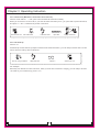
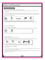
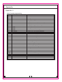
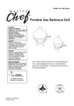
PABX
Telephone Switch
User's Manual
ISO 9001:2000 Certificate
Please read this manual before use
COPY RIGHT RESERVED
Table of Contents
Chapter 1 Installation & Connection
. . . . . . .
Name of Parts
Safety Installation Precautions
. . .
Wiring Precautions
. .
Operating Instructions
.
.
.
.
.
.
.
.
.
.
WARNING
. . . . . . . . . . . . . . . . . . . . . . . . . . . . . . . . . . . . . . . . . . . . . . . . . 1
. . . . . . . . . . . . . . . . . . . . . . . . . . . . . . . . . . . . . . . . . . . . . . 2
. . . . . . . . . . . . . . . . . . . . . . . . . . . . . . . . . . . . . . . . . . . . . . . . . 2
. . . . . . . . . . . . . . . . . . . . . . . . . . . . . . . . . . . . . . . . . . . . . . . . . 2
. . . . . . . . . . . . . . . . . . . . . . . . . . . . . . . . . . . . . . . . . . . . . . . . . 2
Chapter 2 System Programming
. . . . . . . . . . . . . . . . . . . . . . . . . . . . . . . . . . . . . . . . . . . . . . 3
Before System Programming
. . . . . . . . . . . . . . . . . . . . . . . . . . . . . . . . . . . . . . . . . . . . . . . . . . . . . . 3
System Password
. . . . . . . . . . . . . . . . . . . . . . . . . . . . . . . . . . . . . 4
Outside (CO) Line Connection Assignment
. . . . . . . . . . . . . . . . . . . . . . . . . . . . . . . . . . . . . . . . 4
Incoming Calls Ring Specific Extension
Trunk Group . . . . . . . . . . . . . . . . . . . . . . . . . . . . . . . . . . . . . . . . . . . . . . . . . . . . . . . . . . . 5
. . . . . . . . . . . . . . . . . . . . . . . . . . . . . . . . . . . . . . . . . . . . . . . 6
Attendant Mode Assignment
. . . . . . . . . . . . . . . . . . . . . . . . . . . . . . . . . . . . . . . . . 7
Outgoing Message (OGM) Recording
. . . . . . . . . . . . . . . . . . . . . . . . . . . . . . . . . . . . . . 8
Extension Class And Restriction Assignment
. . . . . . . . . . . . . . . . . . . . . . . . . . . . . . . . . . . . . . . . . . . . . . . . . . . . . . . . . 10
Outgoing Call
. . . . . . . . . . . . . . . . . . . . . . . . . . . . . . . . . . . . . . . 10
Hook-Switch Flash Time Range Assignment
. . . . . . . . . . . . . . . . . . . . . . . . . . . . . . . . . . . . . . . . . . 11
PC Bill Charging System Assignment
.
.
.
.
.
.
.
.
. . . . . . . . . . . . . . . . . . . . . . . . . . . . . . . . . . . . . . . . . 11
Caller ID Mode Assignment
Change The Extension Number . . . . . . . . . . . . . . . . . . . . . . . . . . . . . . . . . . . . . . . . . . . . . . . . 11
Monitor Recording Assignment . . . . . . . . . . . . . . . . . . . . . . . . . . . . . . . . . . . . . . . . . . . . . . . . 12
. . . . . . . . . . . . . . . . . . . . . . . . . . . . . . . . . . . . . . . . . . . . . . . . 13
System Data Default Setting
.
.
. . . . . . . . . . . . . . . . . . . . . . . . . . . . . . . . . . . . . . . . . . . . . . . 14
CO Line Call is Received
Outgoing Call
. . . . . . . . . . . . . . . . . . . . . . . . . . . . . . . . . . . . . . . . . . . . . . . . . . . . . . . . . 15
. . . . . . . . . . . . . . . . . . . . . . . . . . . . . . . . . . . . . . . . . . . . . . . . . . . . . 16
Make Intercom Call
Chapter 3 Operating Instruction
. . . . . . . . . . . . . . . . . . . . . . . . . . . . . . . . . . . . . . . . . . . . . . . . . . . . . 17
. . . . . . . . . . . . . . . . . . . . . . . . . . . . . . . . . . 18
Conference ( Between 2 Extensions And 1 Line )
Call Transferring
Call Pick up
Call Forwarding
. . . . . . . . . . . . . . . . . . . . . . . . . . . . . . . . . . . . . . . . . . . . . . . . . . . . . . . . 18
. . . . . . . . . . . . . . . . . . . . . . . . . . . . . . . . . . . . . . . . . . . . . . . . . . . . . . . 19
. . . . . . . . . . . . . . . . . . . . . . . . . . . . . . . . . . . . . . . . . . . . . . . . . . . . . . . 19
Priority Access
Self Inquiry Extension Number
. . . . . . . . . . . . . . . . . . . . . . . . . . . . . . . . . . . . . . . . . . . . . . . 19
Appendix 1
PC Bill Charging System Installation
. . . . . . . . . . . . . . . . . . . . . . . . . . . . . . . . . . . . . . . . . . . 20
System Setting
. . . . . . . . . . . . . . . . . . . . . . . . . . . . . . . . . . . . . . . . . . . . . . . . . . . . . 20
Illumination of PC Monitor
. . . . . . . . . . . . . . . . . . . . . . . . . . . . . . . . . . . . . . . . . . . . . . . . 21
Extension Monitor
. . . . . . . . . . . . . . . . . . . . . . . . . . . . . . . . . . . . . . . . . . . . . . . . . . . . . 21
Bill Inquiry
. . . . . . . . . . . . . . . . . . . . . . . . . . . . . . . . . . . . . . . . . . . . . . . . . . . . . . . . . . 21
Charging Parameters Setting
. . . . . . . . . . . . . . . . . . . . . . . . . . . . . . . . . . . . . . . . . . . . . . . . 22
Host Setting
. . . . . . . . . . . . . . . . . . . . . . . . . . . . . . . . . . . . . . . . . . . . . . . . . . . . . . . . 22
Points For Attentions
Appendix 2
. . . . . . . . . . . . . . . . . . . . . . . . . . . . . . . . . . . . . . . . . . . . . . . . . . . . . 23
Default Setting Mode List
. . . . . . . . . . . . . . . . . . . . . . . . . . . . . . . . . . . . . . . . . . . . . . . . . . 23
Appendix 3
Voice Recorder
Appendix 4
. . . . . . . . . . . . . . . . . . . . . . . . . . . . . . . . . . . . . . . . . . . . . . . . . . . . . . . . 23
Index of System Programming
. . . . . . . . . . . . . . . . . . . . . . . . . . . . . . . . . . . . . . . . . . . . . 24
Chapter 1 Installation & Connection
Name of Parts
1. LED
2. Power Switch
3. Power Socket
1
2
Front View
4. Power Fuse
5. External Music Input port
4
6
8
9
6. COM port (For PC)
7. Monitor Recorder port
8. CO Line board (CO Line port
number)
9. Extension line board (Extension
3
5
7
Back View
line port number)
Before Installation
Please read following notes concerning installation & connection before install system.
Safety Installation Precautions
When installing telephone wire, basic safety precautions should always be followed to reduce the
risk fire, electric shock and injury to persons, including the following:
1. Never install telephone wire during a lightning storm;
2. Never install telephone jacks in wet locations unless the jack is specifically designed for wet locations;
3. Never touch annulated telephone wires or terminals unless the telephone line has been disconnected
at the network interface;
4. Use caution when installing or modifying telephone lines;
Avoid installing in the following places (doing so may result in malfunction, noise or discoloration)
1. In direct sunlight and hot, cold or humid places.
2. Sulfur gases produced in areas where there are thermal springs, etc may damage the equipment or
contacts.
3. Places in which shocks or vibrations are frequent or strong;
4. Dusty places or places where water or oil may come into contact with the unit;
5. Near high-frequency generating devices such as sewing machines or electric welders;
6. On or near computers, telexes or other office equipment, as well as microwave ovens or air conditioners;
7. Install at least 1.8m (6feet) from radios and televisions (Both the main unit and a proprietary telephone)
8. Do not obstruct area around the main unit (for reasons of maintenance and inspection-be especially
careful to allow space for cooling above and at the sides of main unit);
Chapter 1 Installation & Connection
Wiring Precautions
Make sure to keep the following instructions when wiring.
1. Don't wire the telephone cable in parallel with an AC power source, computer, telex, etc. If the cables are run near
those wires, shield the cables with metal tubing or use shielded cables and ground the shields.
2. If cables are run on the floor, use protectors or the like to protect the wires where they may be stepped on. Avoid
wiring under carpets.
3. Avoid using the same power supply outlet for computers, telexes and other office equipment. Otherwise, system
operation may be interrupted by the induction noise from such equipment.
4. The AC cord must be plugged off during wiring, after all the wirings are completed, plug AC cord into an AC outlet.
5. Wrong wiring may cause the system to operate improperly.
6. If an extension doesn't operate properly, disconnect the telephone from extension line and then connect again or
plug off the AC cord of system and re-connect it.
7. Suggest equipping lightning arresters for CO Lines.
Operating Instructions
1. Better to equip lightning arresters for CO Lines, the resistance of arrester ground connection must be less than
10ohm. Keep the well ground connection of the metal case to avoid interference;
2. You can insert or take out the CO line or extension line boards upright even don't turn off the power, and please
ensure the inserted boards have been fixed tighten the screws;
3. This system is adopting Power Switch, range of input power is 80V ~ 260V. Power Switch is just to control the
parts of battery and DC, don't control input 220V power. Please turn off the power switch and disconnect the
power source if stop to using the system.
4. Built internal battery with safeguard, auto power supply in case of power failure and auto charge. Below is the
reference time usage list of power failure:
Waiting status
1 pair of people
Over 24 hours
20 hours
2 pairs of people
12 hours
3 pairs of people
4 pairs of people
8 hours
6 hours
5. When you input external music it will replace of the internal music, and the external music source should be
keeping ON, the range of input signal voltage is 0.5V ~ 2V. The monitor port is exclusively for connect with voice
recorder (appendix 3);
6. COM port is adopt standard RS232 that compatible with COM port of PC to build internal network charging system
by support of software (appendix 1);
7. Suggest to using high quality telephone. Caller ID is realizable under FSK or DTMF mode for both of auto-attendant
or operator-attendant mode, and the number is still visible after the call is transferred. However, Caller ID may not
work properly in some areas due to interference of signal or lines there.
8. Study this manual carefully before programming to avoid wrong entry cause the system doesn't work normally, you
can reset the power to test system again if have problem. For any technical problem or repair on your set, please
send it to the authorized dealers, importer or manufacturer, avoid open up the unit by yourself.
Note: Lightning damaged is attributed to accident that is ex normal warranty.
WARNING
THIS UNIT MAY ONLY BE INSTALLED AND SERVED BY QUALIFIED SERVICE PERSONNEL.
WHEN A FAILURE OCCURS WHICH RESULTS IN THE INTERNAL PARTS BECOMING ACCESSIBLE,
DISCONNECT THE POWER SUPPLY CORD IMMEDIATELY AND RETURN THIS UNIT TO YOUR DEALER.
DISCONNECT THE TELECOM CONNECTION BEFORE DISCONNECTING THE POWER CONNECTION PRIOR
TO RELOCATING THE EQUIPMENT, AND RECONNECT THE POWER FIRST.
THE POWER SUPPLY CORD IS USED AS THE MAIN DISCONNECT DEVICE, ENSURE THAT THE SOCKET
-OUTLET IS LOCATED/INSTALLED NEAR THE EQUIPMENT AN IS EASILY ACCESSIBLE.
TO PREVENT FIRE OR SHOCK HAZARD, DO NOT EXPOSE THIS PRODUCT TO RAIN OR MOISTURE.
Chapter 2 System Programming
2.0 Before System Programming
2.0.1 This system has factory default settings (appendix 2), you can change the setting by System Programming if
necessary. Any required changes can be written in the programming tables listed in appendix 4;
2.0.2 System programming should be operated on Extension 801; the system password can be changed by
program (2.1.1);
2.0.3 Assign the password required for entering the system programming mode;
2.0.4 Input * to start programming, and # to ending; you will hear 1 beep tone informs you that programming is
completed, you can continue programming by enter program format, if you have wrong entry, you will hear an
alarm tone (3 beeps), try again.
If Extension 801 is under Direct Outgoing mode, you can press * to enter internal line first, and then input
another * to start programming.
2.1 System Password
2.1.0 Un-lock Password
Format: *01 ABCD #
ABCD is the system password, assigns the password is required for entering the programming mode, suppose the
password is 1234 .
0
*
Pick up 801
Input
1 1 2 3
4
#
01 1234 #
beep
programming
The system will be locked automatically as soon as extension 801 is off-hook; so please keep
extension 801 is on-hook after un-lock password, and start to program when you hear 1 beep tone.
Once if you off-hook, you need to input password again to un-lock system.
2.1.1 Change Password
Format: * 02 ABCD #
ABCD is new password.
For example, you want to change the password to 0000 :
*
Pick up 801(unlock)
0 2
0 0
0 0 #
Input "* 0 2 0 0 0 0 #";
beep
Hang up
The default password is 1234 , we suggest to assign new password before using.
Following programming examples are under Un-lock password mode:
Chapter 2 System Programming
2.2 Outside (CO) Line Connection
Format: * 3 a b c d e f #
a b c d e f are the CO Line ports that for connect with CO lines;
For example: Your company have four CO Lines, you can connect the CO Lines with port 1 to port 4, and assign the
system as four CO Line mode;
*
Pick up 801(unlock)
3
1
2
3
4
#
Input * 3 1234 #";
"beep"
Hang Up
During the practical operating, the user can connect the CO Lines doesn't according the port order if necessary.
For example, connect four CO lines to port 2, port 4, port 5 and port 6:
*
Pick up 801(unlock)
3
2
4
5
6
#
Input * 3 2456 #";
"beep"
Hang Up
If you want to use PABX as Intercom use only, you can assign the system as none CO Line mode;
*
Pick up 801(unlock)
3
Input * 3
#
#";
"beep"
Hang Up
2.3 Incoming Calls Ring Specific Extensions
Format: * 1 m abcd #
m is the CO Line port number, a, b, c, d is the last digit of extension port number.
For example: If you want to assign extension 802 is ringing when CO 1 is incoming,
extension 803 and 806 are ringing when CO 2 is incoming:
*
1 1
*
2 #
Pick up 801(unlock) Input "* 1 1 2 #";
"beep"
1 2
3 6
Input"* 1 2 3 6 #";
#
beep"
Note:
a) The default ringing extensions are 801 to 804;
b) The ringing extensions are allows assigned only among extension 801 to 808.
4
Hang up
Chapter 2 System Programming
2.4 Trunk Group
2.4.1 Specific CO Line(s) as exclusively trunk for designated extension(s)
Format: * 4 1 m abc #
m is the CO Line port number; abc is the extension number;
For example: Assign Co3 as exclusively trunk for extension 803 and 335:
1 3 8 0
* 4
Pick up 801(unlock)
Input
3 #
* 4
4 1 3 803 #
1 3 3 3
5 #
Input * 4 1 3 335 #
beep
beep
Hang up
Note:
a) Maximum allows have four extensions for CO Line;
b) To clear this programming (2.4.1), you can assign the CO Line connection again according item 2.2.
c) Other extensions are not allows to access these CO Lines even if they are free.
2.4.2 Appointed extension(s) only allows access to specific CO Line(s)
Format: * 4 2 m abc #
m is CO Line port number; abc is extensions number;
For example: Assign extension 807 only allows access to CO 3, and extension 818 only
allows access to CO 5:
*
Pick up 801(unlock)
4 2
Input
3 8 0
7
5 8 1
#
4 2 3 807 #
beep
Input * 5 818 #
8
#
Hang up
Note:
To clear this programming (2.3.1), you can assign the CO Line connection again according item 2.2.
5
Chapter 2 System Programming
2.5 Attendant Mode Assignment
2.5.1 Assign Operator Attendant for all CO Lines
Format: * 2 1 #
The ringing extension will ring (2.4) when an outside call is incoming, the operator can pick up to answer directly.
* 2
Pick up 801(unlock)
1 #
Input "* 2 1 #";
"beep"
Hang up
2.5.2 Assign Auto-Attendant for all CO Lines
Format: * 2 0 #
Allows the extension assigned as an operator to record of maximum 20 seconds message (2.5.6) is play when
a caller accesses the DISA feature. All extensions will not ring when CO line call is incoming.
* 2
Pick up 801(unlock)
0 #
Input"* 2 0 #";
"beep"
Hang up
Note:
The outside caller can press 0 to operator in the case of un-know the extension number; the line will be auto
transfer to No.2 operator if No.1 operator is busy; and the system will look for idle extensions among 802 to 808
if both of operators are busy, the idle extension will ring, you can pick it up to answer the call.
This assignment is not function for intercom.
2.5.3 Assign Auto-Attendant for Specific CO Line(s)
Format: * 2 0 m #
m is the CO Line port number(1 to 6)
For example: Assign Auto-Attendant mode for CO2 and CO 4, and Operator-Attendant mode for others.
*
2
0
*
2 #
Pick up 801(unlock) Input"* 2 0 2 #";
"beep"
2
0
4 #
Input"* 2 0 4 #"
Hang up
Note:
Suggest to assign Operator-Attendant mode for all CO Lines by format * 2 1 # before this assignment (2.5.3) to
avoid conflicts with previous setting.
6
Chapter 2 System Programming
2.5.4 No.1 Attendant Extension Assignment
Format: * 2 5 abc #
abc is the extension number, you can change the attendant extension if necessary.
For example: Assign extension 807 as No.1 attendant extension:
*
2 5
Pick up 801(unlock)
8 0
7 #
Input "* 2 5 8 0 7 #";
"beep"
Hang up
2.5.5 No.2 Attendant Extension Assignment
Format: * 2 6 abc #
abc is extension number; the line will be transferred to No.2 operator if No.1 operator is busy when the outside
caller dial 0 ,
For example: Assign extension 806 as the No.2 attendant extension:
*
Pick up 801(unlock)
2
6
8
0
6
#
Input"* 2 6 8 0 6 #";
"beep"
Hang up
Note:
The default No.1 attendant extension is 802, extension 803 is No.2 attendant extension;
2.5.6 Outgoing Message (OGM) Recording
Format: * 2 2 #
Allow you to record outgoing message for Direct Inward System Access (DISA), message example: Welcome to
ABC Company, please dial extension number, dial "0' to operator." Outside caller will hear this outgoing message,
he can dial the extension number directly, the called extension will ring, and the caller is under music on holding.
* 2
Pick up 801(unlock)
2 #
Input"* 2 2 #";
"beep"
Hang up
Note:
a) The recording time is a maximum of 20 seconds;
b) Please pick up extension 801 when recording to ensure the optimum record message;
c) The last message will be took place of the previous recording;
d) Message will be stop playing as soon as the caller dial any number in advanced;
2.5.7 OGM Play
Format: * 2 3 #
To play the Recorded Message as reference, if the message is not satisfied, you can record again (2.5.6);
2.5.8 Holding Music Play
Format: * 2 4 #
You can listen the nice holding music play.
7
Chapter 2 System Programming
2.6 Extension Class and Restriction Assignment
2.6.1 Class Assignment for Specific Extension
Format: * 5 8 abc n #
" abc" is the extension number; " n" is the extension class;
"n"=0 No any restriction;
"n"=1 The numbers with lead digits in Group 1 Restricted are not allow to dial;
"n"=2 The numbers with lead digits in Group 2 Restricted are not allow to dial;
"n"=3 The numbers with lead digits in Group 3 Restricted are not allow to dial;
"n"=4 The numbers with lead digits in Group 4 Restricted are not allow to dial;
"n"=5 only allow to dial the numbers with lead digits in Group 1 Special;
"n"=6 only allow to dial the numbers with lead digits in Group 2 Special;
"n"=7 Intercom Only;
For example:
Extension 806 is not allow to dial the numbers with lead digits in Group 1 Restricted (2.6.3),
extension 809 only allow to dial the numbers with lead digits in Group 2 Special (2.6.3), and
extension 823 is only permit Intercom;
The default mode is n=0
*
8 8 0 6
5
Pick up 801
and unlock
1 #
Input" * 5 8 806 1 #";
8 0 9
"beep"
6 #
Input" 809 6 #";
8 2 3
"beep"
7 #
Input" 823 7 #"
Hang up
Note
"Group 1 Restricted" means the numbers with lead digits that in Group 1 are not permit to be dial;
"Group 1 Special" means only permit to dial the numbers with lead digits that in Group 1.
2.6.2 Same Class Assignment for Most of Extensions
Format: * 5 8 n #
"n" is the extension class;
You can assign same class for most of extensions more convenient and speed by this programming.
For example: Assign extension 804 and 810 are without any restriction for outgoing call (n=0), other
extensions only permit to dial local call (assign the lead digit is "0" in Group 1 Restricted, n=1 ); you
can assign n=1 for all extensions first, then assign n=0 for extension 804 and 810:
*
Pick up 801
and unlock
5
8 1 #
Input" * 5 8 1 #";
8 0 4
"beep"
0 #
Input" 804 0 #"
8
8
"beep"
1 0
0 #
Input" 810 0 #"
Hang up
Chapter 2 System Programming
2.6.3 Assign Lead Digits for each Group
Format: * 5 n abcd #
When n is 1, 2, 3 , 4, means the lead digits in Group 1 Restricted to Group 4 Restricted;
When n is 5, 6, means the lead digits in Group 1 Special and Group 2 Special;
"abcd" is lead digits;
For example: Assign "25" and "0" as the lead digits in Group 4 Restricted;
* 5
Pick up 801(unlock)
4 2 5 #
0 #
Input"* 5 4 25 #"
"beep"
Input"0 #";
"beep"
Hang up
For example: Assign "11" and "200" as the lead digits for Group 1 Special (n=5):
*
5
5 1 1 #
2
Pick up 801(unlock) Input"* 5 5 11 #";
"beep"
0 0
#
Input "200 #";
"beep"
Hang up
a)Permit to assign up to four digits as lead digits, completed with #;
b)Maximum allow assign twenty pieces of lead digits for each group;
2.6.4 Clear Lead Digits for Group N
Format: * 5 n #
To change the lead digits for group N, you can use this programming to clear the current lead digits first.
2.6.5 Call Duration Restricted
Format: * 9 abc MN #
Format: * 9 MN # (Assign Call Duration Restricted for all extensions)
" abc" is extension number;
"MN" is the call duration, from 1 minute to 99 minutes;
The system will disconnect outgoing call when a specific time expires.
For example: Assign 5 minutes as call duration for extension 803:
*
Pick up 801(unlock)
9
8 0 3 1
#
Input"* 9 803 5 #";
"beep"
Hang up
The call will be auto disconnect after 5 minutes when extension 803 making outgoing call.
Note:
a) The actual call duration has about 20 seconds discrepancy from the duration that you have been assigned
in order to counteract your dialing time;
b) Call duration is from 1 minute to 99 minutes;
2.6.6 Clear Restriction of Call Duration
Format: * 9 abc #
Format: * 9 # (clear call duration for all extensions)
" abc" is extension number, there is no any time restriction after clear Call Duration Restricted.
9
Chapter 2 System Programming
2.7 Outgoing Call
2.7.1 Dial Mode Assignment
Format; * 8 abc n #
" abc" is the extension number;
"n"=0 means press "0" or pat the hook-switch to make outgoing call;
"n"=1 means direct dial mode;
For example: Assign direct outgoing mode for extension 803, 805 and 808:
*
Pick up 801
and unlock
8
8
0
3
1
#
Input"* 8 803 1 #";
8
"beep"
0
5
1
#
8
Input"* 8 805 1 #";
"beep"
0
8
1
#
Input"* 8 808 1 #";
Hang up
When you want to make intercom call, you need to press * abc (abc is extension number) if your extension is
under direct outgoing mode;
The default mode is n=0;
2.7.2 Clear Direct Dial Mode for All Extensions
Format: * 8 000 #
You can use this programming to clear direct dail mode for all extensions before you adjust the outgoing
mode for the most of extensions.
The extension will be under dial "0" or pat hook-switch dial mode after clear direct dail mode.
2.8 Appendix Setting
2.8.1 Hook-switch Flash Time Range Assignment
Format: * 8 1 m #
"m" is the class of flash time;
"m"=1 means 750ms;
"m"=2 means 1000ms;
"m"=3 means 1200ms;
"m"=4 means 1500ms;
"m"=5 means 2000ms;
For example:
Assign flash time 1000ms to adapt the hook-switch flash time of telephone (m=2):
* 8
Pick up 801(unlock)
1 2 #
Input"* 8 1 2 #";
"beep"
Hang up
Note:
The default flash time is 750ms;
10
Chapter 2 System Programming
2.8.2 PC Bill Charging System Assignment (Appendix 1)
Format: * 8 2 n #
n=0 means Delay Charging mode;
n=1 means Reserve Charging mode;
Delay Charging mode means the system will start to charge after specific duration when the user enter CO
Line, this duration is the Delay Duration;
Reserve Charging mode means the system will not start to charge until the call is answered. You should
apply this service from local telecom office first.
2.8.3 Caller ID Mode Assignment
Format: * 27 n #
n=0 means the FSK mode;
n=1 means the DTMF mode;
To better receive Caller ID signal; we can assign proper Caller ID mode.
Default mode is FSK.
For example:
Press * 27 1 # if the Caller ID mode is DTMF; you can change the programming to find out what kind of
mode in the case you are not sure.
#
Pick up 801(unlock)
2 7
1
Input "*271#"
Listen Dial Tone
Hang up
Caller ID has following practical cases when you are using:
a) Intercom: There is showing 00abc in the monitor of called extension (abc is current extension number).
b) Operator Attendant: CO line number will be shown in the operator's extension after one ring before it is
transferred, other extensions are not visible.
c) Auto-Attendant: CO line number will be shown in the called extension after one ring, other extensions are
not visible.
d) Call Transfer to other Extension: CO line number is still visible even after the CO line call is transferred to
other extensions many times.
Note:
Caller ID signal is conveyed between first ring and second ring, so we better to answer the call after second
ring, otherwise may cause number in-complete or in-visible at all.
In some areas, Caller ID may not work normally due to interference of signal or lines.
11
Chapter 2 System Programming
2.9 Flexible Coding
2.9.1 Change the Extension number
Format: * 7 ABC abc #
"ABC" is the current extension number;
"abc" is the new extension number that you want to change to be;
For example: Change the extension number "814" to "537", "820" to " 881" and "826" to "652":
*
Pick up 801
and unlock
7 8 1 4 5
3 7
#
8 2 0
Input "* 7 814 537 #"
"beep"
8
8
8 2 6
1 #
Input"820 881 #";
6
5
2 #
"beep" Input "826 652 #";
Hang up
Note:
a)New extension number must be among "100" to "999";
b)New extension number are not allow same as current extension number;
2.9.2 Restore Extension Number
Format: * 7 000 #
You can use this format to restore the extension number to default mode before you want to do adjusting for
the most of extensions to avoid reduplicate number.
2.10 Monitor Recording Assignment
2.10.1 Auto Monitor Record for Specific Extension
Format: * 4 3 abc n #
"abc" is extension number;
"n"=0 means Turn OFF the monitor recording;
"n"=1 means Turn ON the monitor recording;
The Voice Recorder will be auto start to record as soon as the assigned extension is picked up and will be
stop recording till extension complete conversation; (appendix 2)
For example: Assign extension 803 and 807 as be monitor record extensions;
* 4 3
8 0 3 1
#
Pick up 801(unlock) Input"* 4 3 803 1 #"
8 0 7
"beep"
1 #
Input "807 1 #"
"beep"
Hang up
Note:
When extension 803 is under monitor recording, at the same time, if extension 807 is picked up,
extension 807 will not start to be recorded until extension 803 is complete conversation.
It is say, only one extension is allowed be monitor record at the same time.
2.10.2 Clear Monitor Recording for all Extensions
Format: * 4 3 #
You can use this programming to clear monitor recording for all extensions before you want to do adjusting
for the most of extensions.
12
Chapter 2 System Programming
2.10.3 Auto Monitor Record for Specific CO Line
Format: * 4 4 m n #
"m" is the CO Line port number (1 ~ 6 )
"n"=0 means Turn OFF the monitor recording;
"n"=1 means Turn ON the monitor recording
The Voice Recorder will be auto start to record as soon as the assigned CO Line is connected and will be
stop recording till complete conversation;
For example: Assign CO 1 and CO3 as be monitor record CO Lines;
* 4 4
Pick up 801(unlock)
3 1 #
1 1
Input" * 44 3 1 #"
"beep"
#
Input" 11 #"
"beep"
Hang up
Note:
When CO 1 is under monitor recording, at the same time, if CO3 is connected, CO3 will not start to be
recorded until CO1 is complete conversation. It is say, only one CO Line is allowed be monitor record
at the same time.
2.10.4 Clear Monitor Recording for all CO Lines
Format: * 4 4 #
You can use this programming to clear monitor recording for all CO Lines before you want to do adjusting for
the most of CO Lines.
2.11 System Data Default Setting
Format: * 6 000 #
*
Pick up 801(unlock)
6
0
0
0
#
Input" * 6 000 #"
"beep"
Hang up
You can restore the system to default mode in the case of forget the system-programmed, and re-program.
Note:
a) This program will not restore default extension number
b) This program will not change the CO Line Connection Assignment, but will be clear the Trunk Group setting;
13
Chapter 3 Operating Instruction
3.1 Answer Incoming Call
3.1.1 Operator Attendant
Operator Attendant means that the assigned ringing extension will ring (1sec:4sec) when CO Line is received,
pick up the extension to answer the call.
Operator attendant suits for the occasions that have person on duty.
Ringing
Pick up
Talking
Hang up
You can answer the CO Line call by pick up the ringing extension, if you want to answer the call by un-ring
extension, you can use Call Pick Up function (2.4)
3.1.2 Auto-Attendant
Auto-Attendant is suits for the occasions that haven't person on duty; the outside caller can dial extension
number according to OGM guidance or dial 0 to operator.
For example:
You can record message Welcome to ABC Company, please dial extension number, dial "0' to operator."
Note:
a)If the called extension doesn't answer after 25 seconds, the line will be auto disconnected;
b)The No.1 attendant extension will ring after the outside caller press 0 , and the call will be auto transferred
to No.2 attendant extension if No.1 attendant extension is busy. The system will auto look for idle extensions
from extension 802 in the case of both attendant extensions are busy. ( 2.5.4 and 2.5.5)
14
Chapter 3 Operating Instruction
3.2 Outgoing Call
3.2.1 Make CO Line call
There are have four kinds of outgoing call mode: Direct Outward, Pat Hook-switch, Press 0 and select
CO Line;
a b
Pick up
Listen Dial Tone
c d e f
Input CO line number
Talking
Hang up
a) Direct Outward:
You can input the CO Line number directly after you hear the dial tone; you need to press * abc (abc is called
extension number) if you want to make intercom call when your extension is under Direct Outward mode.
It require to complete dial at least four digits in 8 seconds, otherwise, the line will be disconnect.
b) Outward by Press 0
You can press 0' after you hear the intercom dial tone, after while, you can continue to input CO Line number
when you hear CO Line dial tone.
c) Outward by pat the hook-switch
You can pat the hook-switch after you hear the intercom dial tone, after while, you can continue to input
CO Line number or you can press Redial button to redial when you hear CO Line dial tone.
When you are use outward dial mode among above three kinds, the system will auto look for the idle CO Line
start from CO1.
If you hear busy tone after you pat the hook-switch or press 0 that informs you there are no free CO Lines
(ignore the extension have been assigned any restriction), you can hang up to wait a moment.
Note:
a) You should complete to dial at least four digits after 8 seconds when you are make outward call, otherwise,
the line will be disconnected.
b) You can press Redial button to redial when your extension is under Direct Outward mode; however, you
should pat the hook-switch or press 0 + Pause button +Redial button to make outward call when your
extension is not under Direct Outward mode.
d) Outward by Specific Line
Format: # n
n is the CO Line port (1~6)
A proprietary telephone user can select a desired CO line preference to make outside calls.
For example: If you want to make outward call via CO3, you can press # in 5 seconds after hear dial tone,
and then input 3 to enter the CO 3;If you hear busy tone after press # 3 that informs you other occupies
CO 3, hang up to waiting.
15
Chapter 3 Operating Instruction
3.2.2 Make Intercom Call
You can make intercom call by input extension number in 5 seconds after hear intercom dial tone when your
extension is not under Direct Outward mode. If you hear busy tone that informs you the called extension may
busy or you have wrong entry, please try again.
However, you need to press * abc (abc is called extension number) when your extension is under Direct
Outward mode.
* 8
Pick up 805
Listen Dial Tone
0 7
Input"* 807"
Intercom
Hang up
For example: Extension 805 is not under direct outward mode. If he wants to call extension 807, he just
need to input extension number 807 directly after he heard intercom dial tone, and he will hear busy tone
if extension 807 is busy. When extension 805 is under direct outward mode, he should input * 807 to call
extension 807.
16
Chapter 3 Operating Instruction
3.3 Call Transferring
3.3.1 Caller on Waiting
Format: Hook-switch + # 99
For example: The CO Line number is 1234567, when attendant extension 805 is talking with outside caller 1,
meanwhile, caller 2 is dial the same number 1234567, so 805 can hear beep tone informs him there has
second call is incoming. She can pat the hook-switch, and input # 99 to hold the caller 1 and connect with
caller 2, caller 1 is under music on holding at the moment. After complete conversation with caller 2, she
can pat the hook-switch and input #99 to restore the talking with caller 1.
Note:
1)The user should apply this service from the Telecom Office first;
2)This feature only effect when the caller 2 dial the same CO Line number.
3.3.2 Call Transfer to Extension
Format: Hook-switch + abc (abc is the transferred extension number)
When extension A is received a CO Line call, he can pat the hook-switch or Flash Button
(outside caller is under music on holding mode) and continue to input extension number
(suppose called extension number 808) after he heard dial tone, extension 808 will start
ringing. Pat the hook-switch (or Flash button), and then input 808
8
Receive CO line
Pat hook-switch
Listen Dial Tone
0 8
Input808
There are would have following cases when extension A is transferring CO Line call to extension B:
a)A doesn't hang up, B picks up, A can make intercom conversation with B, outside caller is
under music on holding mode. Any one of them between A and B is hang up; the other party
will connect with CO Line.
b)A doesn't hang up, B doesn't pick up in 25 seconds, A will restore communication with
CO Line, extension B will stop ringing;
c)A hangs up, B picks up to answer CO Line;
d)A hangs up, B doesn't pick up in 25 seconds. A will ring again if it is idle; B will stop
ringing. A can pick up to answer at the moment, if A is busy, the line will be disconnected.
Note:
Extension A will hear dial tone after he press the hook-switch, and he should complete
transferred extension number in five seconds, otherwise, his extension will be restore to
connect with CO line; ( Flash time assignment 2.8.1)
17
Chapter 3 Operating Instruction
3.3.3 Conference (Between 2 extensions and 1 CO line)
Format: Hook-switch + * + abc (abc is the transferred extension number)
When you receive an CO Line call, if you want another extension join in, you just need to pat hook-switch,
and press "* + abc " to build three parties conference.
*
Receive CO Line
Pat hook-switch
Listen Dial Tone
8 0 7
Input *807
3-party conference
3.3.4 Call Pick Up
Format: # 7
Call Pick Up means when the people is absent from called extension, you can help to answer the CO Line
call or Intercom call by other extensions.
#
Pick up un-ring extension
Listen Dial Tone
7
Input"# 7"
Answer CO Line
For example:
Secretary A is absent from her extension, when you hear her extension is ringing, you can help to answer
the calls on your extension by press " # 7 ".
18
Chapter 3 Operating Instruction
3.4 Appendix Functions
3.4.1 Call Forwarding
Format: # * abc ( abc is the extension number of destination)
Call Forwarding means allows an assigned extension auto transfer incoming calls to another extension.
For example:
Your extension number is 805, you need to handle some works in another office that the extension number
is 807, to avoid miss the calls to extension 805, you can assign all incoming calls to extension 805 will be
auto transfer to extension 807.
#
Pick up 805
Listen Dial Tone
* 8
0 7
Input "# * 807"
Long"beep"
Hang up
Note: This programming is invalid for Attendant-extension when under operator attendant mode.
3.4.2 Clear Call Forwarding
Format: Pick Up Assigned Extension
To clear call-forwarding assignment, you just need to pick up assigned extension, and then hang up.
Pick up 805;
Hang up
3.4.3 Priority Access
Format; # 9 n (n is the CO Line port number)
Allows user of extension 801 enable to access certain CO line even this CO line is using by others.
#
Pick up 801(unlock)
Listen Dial Tone
9
3
Input"# 9 3"
CO Line join in (3 parties)
3.4.4 Self Inquiry Extension Number
Format: # 82
If you want to know the extension number, you can press # 82 on the Caller ID telephone set, the extension
number will be shown in monitor of telephone.
For example: The extension 804 has been changed to extension number123, so you can notice that there is
showing "804123" on monitor.
19
Appendix
Appendix 1
PC Bill Charging System Instruction
1.PC Bill Charging System Installation
Input supplied CD Disk into CD-ROM, open PC Bill Charging System , click SETUP.EXE to start installation.
Complete operating according to guidance;
Click Start to enter PC Bill Charging system by click PC Bill Charging System
Monitor 1
Monitor 2
(Chart 1)
2.System Setting
Click Unlock menu, pop out Inspection Authority , you can select the user, default password of Operator is 1234 ,
and 4321 is for Administrator; click OK after inputted password to enter system programming.
There are have following menus:
(Chart 2)
A) Host Setting: Mainly for assign basic functions of PABX. These functions also can be programmed by
extension 801. If you press * 034567# on extension 801 will pop out System Actual Work State in monitor.
B )Charging Parameters Setting: To assign parameters relate with call fee, such as Charging Rate, Charging Mode,
Delay Duration, etc.
C) Auxiliary Setting: Suck as COM setting, Picture setting, etc;
D) Hotel Management; To convenient for hotel operator inquiry the bill by input room number and extension number;
E) Bill Inquire: You can get a clear bill of Outward call or Incoming call;
F) Address Book: The name of customer, his telephone number and address can be stored in here;
G) User: For change the user's password;
H) Help: You can learn brief introduction about PC Bill Charging System from there;
I) About: Use for inquiry the version of software to system upgrade or maintenance;
20
Appendix
3.Illumination of PC Monitor
3.1 CO Line Monitor (Outward / Incoming)
You can know the actual CO line working state from the monitor.
From Chart 3 , you can notice that extension 801 is making outward call via line 1, and extension 812 is via
line 2. The CO line number is showing in Number list.
(Chart 3)
3.2 Extension Monitor
To see actual working state of extensions by click Actual Monitor 2 at right side (Chart 1).
3.3 Bill Inquiry
Use it to get required call bill.
(Chart 4)
21
Appendix
3.4 Charging Parameters Setting
Click Charging, you can change system-charging parameters; the default mode is Delay Charging mode, there
has few discrepancies between PC output bill and actual cost. If you want to get nicety bill, suggest selecting
Reverse Charging mode, but you need to apply Reverse Charging mode service from local Telecom Office first.
(Chart 5)
3.5 Host Setting
Click Host , the data of host will be auto transferred to PC (Chart 6 and chart 7)
(Chart 6)
All data of host are visible from monitor, and user can change the setting.
(Chart 7)
22
Appendix
4. Points for Attentions
4.1 Better to use supplied cable, if you want to self-make cable, the length of it should not over
20meters to avoid error occur during transfer.
4.2 Ensure the cable complete insert socket, otherwise the COM may be damaged.
4.3 Require using hyper-version4.6 of PC Bill Charging software to get the satisfied performance.
4.4 This software is just for reference to call fee, we don't suggest use it for commercial use.
4.5 If you want to get more complete record of calls, the PC is required to keep ON to operating
this software. The data will not be recorded during the PC is OFF.
4.6 Host Setting or Caller ID may not normal in some areas cause the interference of lines, we
will try our best to do proper adjustment to improve its adaptability.
Appendix 2
Default Setting Mode List
System Password --------------------------1234
Attendant Mode ---------------------------- Operator Attendant Mode
No.1 attendant extension ----------------- 802
No.2 attendant extension ----------------- 801 to 804
Caller ID Mode ------------------------------ FSK
CO Line Connection ----------------------- 1 to 6
Trunk Group --------------------------------- Hasn't programming
Extension Class ---------------------------- n=0
Lead Digits Assignment ------------------- Hasn't programming
Extension number -------------------------- 801 to 832
Outgoing Mode ------------------------------ Press "0" or pat the hook-switch
Appendix 3
Voice Recorder
Our PABX is allow compatible with LH-2000
Voice Recorder that adopt tape. Please
connect the signal line of Voice Recorder
with port of "Monitor" in PABX, and turn on
voice recorder, it will auto start to record
specific extension or CO Line.
23
Appendix
Appendix 4
Index of system programming
No.
Explanation
1
Format
* 0 1 ABCD #
Un-lock Password
2
* 0 2 ABCD #
Change Password
3
* 1 m abcd #
Incoming calls ring specific extensions
4
*20#
Assign Auto-attendant for all CO Lines
5
*20m#
Assign Auto-attendant for specific C.O line(s)
6
*21#
Assign Operator attendant for all CO lines
7
*22#
Outgoing message (OGM) Recording
8
*23#
OGM Play
9
*24#
Holding Music Play
10
*25#
No. 1 attendant extension assignment
11
*26#
No. 2 attendant extension assignment
12
* 3 abcdef #
Outside (CO) Line Connection Assignment
13
* 4 1 m abc #
Specific C.O line(s) as exclusively trunk for designated Extension(s).
14
* 4 2 m abc #
Appointed extension(s) only allows access to specific C.O line(s)
15
* 4 3 abc n #
Auto monitor record for specific extension
16
*43#
Clear monitor recording for all extensions
17
*44mn#
Auto monitor record for specific CO Line
18
*44#
Clear monitor record for alll CO lines
19
* 5 8 abc n #
Class assignment for specific extension
20
*58n#
Same class assignment for most of extensions
21
* 5 n abcd #
Assign lead digits for each group
22
*5n#
Clear lead digits for group n
23
* 6000 #
System Data Default Setting
24
* 7 ABC abc #
Change the extension number
25
* 7 000 #
Restore extension number
26
* 8 abc n #
Outgoing call dial mode assignment
27
* 8 000 #
Clear direct outgoing mode for all extensions
28
*81m#
Hook-switch flash time range selection
29
*82n#
PC bill charging system assignment
30
* 9 abc MN #
Outward call duration restricted
31
* 9 abc #
Clear outward call duration restricted
32
* 27 n #
Caller ID mode assignment
24