1
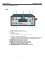
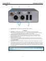
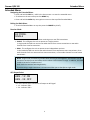
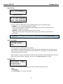
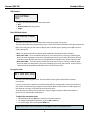
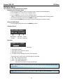
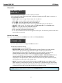
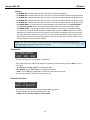
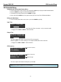
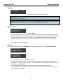
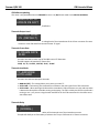
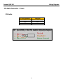
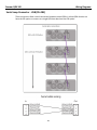
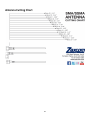
Table of Contents
KNOWING YOUR QRX100 RECEIVER ................................................................................................................ 3
Front .............................................................................................................................................................................................................................................3
Rear ..............................................................................................................................................................................................................................................4
Side ...............................................................................................................................................................................................................................................5
Home Screen.............................................................................................................................................................................................................................6
MAIN MENU ............................................................................................................................................................. 8
Navigating the Main Menu ..................................................................................................................................................................................................8
Exiting the Main Menu ..........................................................................................................................................................................................................8
Frequency Select .......................................................................................................................................................................................................................8
Transmitter Gain Adjustment ...............................................................................................................................................................................................8
Unit Code....................................................................................................................................................................................................................................9
Test Tone ....................................................................................................................................................................................................................................9
Frequency Scan ...................................................................................................................................................................................................................... 10
EXTENDED MENU ................................................................................................................................................ 11
Navigating the Extended Menu ....................................................................................................................................................................................... 11
Exiting the Main Menu ....................................................................................................................................................................................................... 11
Receiver Mode ....................................................................................................................................................................................................................... 11
AES Output Select ................................................................................................................................................................................................................ 11
Output Select.......................................................................................................................................................................................................................... 12
IFB Output Mix ...................................................................................................................................................................................................................... 12
IFB Enable ............................................................................................................................................................................................................................... 12
TX Remote Control .............................................................................................................................................................................................................. 12
Jam TRX Timecode .............................................................................................................................................................................................................. 12
Unit Code................................................................................................................................................................................................................................. 13
Analog Output Routing ........................................................................................................................................................................................................ 13
Software Update ................................................................................................................................................................................................................... 13
Signal Format ......................................................................................................................................................................................................................... 14
Power Save Mode ................................................................................................................................................................................................................. 14
Backlight Timer ...................................................................................................................................................................................................................... 14
LED Dimmer .......................................................................................................................................................................................................................... 15
Blue LED Meter Mode ........................................................................................................................................................................................................ 15
Encryption Code .................................................................................................................................................................................................................... 15
IFB OPTION MENU .............................................................................................................................................. 16
Navigating the IFB Option Menu ..................................................................................................................................................................................... 16
Exiting the Main Menu ....................................................................................................................................................................................................... 16
IFB Home Screen .................................................................................................................................................................................................................. 16
IFB Status................................................................................................................................................................................................................................. 16
IFB Input Mix.......................................................................................................................................................................................................................... 17
Remote Power Mode ........................................................................................................................................................................................................... 17
Timecode Set .......................................................................................................................................................................................................................... 18
Timecode Frame-Rate ......................................................................................................................................................................................................... 18
IFB EXTENDED MENU ......................................................................................................................................... 19
Navigating the IFB Extended Option Menu ................................................................................................................................................................. 19
Exiting the Main Menu ....................................................................................................................................................................................................... 19
Input Trim ............................................................................................................................................................................................................................... 19
Output Trim ............................................................................................................................................................................................................................ 19
IFB Frequency ......................................................................................................................................................................................................................... 19
IFB Mode ................................................................................................................................................................................................................................. 20
Remote Control ...................................................................................................................................................................................................................... 20
IFB Voting................................................................................................................................................................................................................................. 20
IFB Software updating ......................................................................................................................................................................................................... 21
Timecode Output Level ....................................................................................................................................................................................................... 21
Timecode Frame Rate ......................................................................................................................................................................................................... 21
1
Timecode Jam Mode............................................................................................................................................................................................................ 21
Timecode Delay ..................................................................................................................................................................................................................... 21
Timecode Mute Time .......................................................................................................................................................................................................... 22
Audio Delay ............................................................................................................................................................................................................................. 22
ZaxNet Output ...................................................................................................................................................................................................................... 22
IFB Transmit Power Level ................................................................................................................................................................................................... 22
Record Commands ............................................................................................................................................................................................................... 22
Encryption ................................................................................................................................................................................................................................ 23
WIRING DIAGRAMS ............................................................................................................................................. 24
ANTENNA CUTTING CHART ............................................................................................................................ 29
OPERATING FREQUENCIES............................................................................................................................... 30
ZAXNET REMOTE CONTROL AND TIMECODE ...............................................................................................................................................30
UHF AUDIO.........................................................................................................................................................................................................30
FIRMWARE ............................................................................................................................................................. 31
UPDATING THE QRX FROM A 2 CHANNEL TO A 4 CHANNEL RECEIVER.....................................................................................................31
UPGRADING THE QRX (USING A TRX9XX) ..................................................................................................................................................32
UPGRADING THE QRX IFB FIRMWARE (USING A IFB100) ...........................................................................................................................33
UPGRADING THE QRX IFB FIRMWARE (USING A TRX9XX) ........................................................................................................................35
EQUIPMENT SPECIFICATIONS ......................................................................................................................... 37
PRODUCT SUPPORT ........................................................................................................................................... 39
CONSUMER ALERT ..............................................................................................................................................................................................39
ZAXCOM WARRANTY POLICY AND LIMITATIONS .................................................................................... 40
2
Zaxcom QRX 100
Knowing your Receiver
Knowing Your QRX100 Receiver
Front
1.
2.
3.
4.
5.
6.
7.
8.
9.
1
2
5
6
3
4
7
1
8
9
UHF Antenna Connectors - SMA connectors
INC Key - Increases the parameters of a menu item
LCD Display
Receiver Status Indicators
• Solid Red – That particular receiver is not receiving a valid signal
• Red flashes – The QRX is in power save mode
• Solid Green – That receiver is receiving a valid signal, meaning the transmitter is powered up
and operating on the same frequency as the QRX and has a matching encryption code.
Menu Key- press to advance to the next menu item.
Dec Key - decreases the parameters of a menu item.
A/B Key - Press to alternate between receivers in dual mode.
Power Key - Press and hold for 2 seconds to power up the QRX.
Press and hold for 5 seconds to power down the QRX.
ZaxNet Antenna Connector - SMA connector(only with QIFB option)
3
Zaxcom QRX 100
Rear
Knowing your Receiver
1
2
3
5
6
1. DC Power Input - The QRX uses a Switchcraft 761K connector.
2. IFB Audio In - (available with the QIFB option) 3.5mm TRS. (only with QIFB option)
• This connector will accept external audio for IFB transmission when the QIFB is in transmit
mode. It will output ZaxNet audio when the QIFB is in receive mode.
3. Timecode In/Out - (available with the QIFB option) 3.5mm TRS. (only with QIFB option)
This connector will input or output timecode depending on how the connector is wired.
4. Audio out connectors- TA5M.
These connectors will output the audio from the QRX. The same connectors can be used to
output either analog audio or AES audio. The audio assignments for the TA5 connectors are set
in the Extended Menu.
5. Serial Loop -The USB style connectors on the back of the QRX allow multiple QRXs to share a
single common QIFB option board. For example one master QRX with a QIFB option board can
be connected to 3 QRXs with no option boards. The QRXs without option boards will behave as
if they have an IFB option board and will send remote control commands over the serial link to
the master QRX
NOTE: The USB connectors are NOT generic USB connectors that can be used as a connection to
any computer. They are used to exchange RS-422/RS-485 commands. A special cable is required
to do this.
4
Zaxcom QRX 100
Knowing your Receiver
Side
1
2
1. ZaxNet Antenna connector - SMA connector (only with QIFB option)
2. LED - The LED’s give you visual indication if RF and / or audio is being received by the QRX. The
LED settings are adjusted in the Extended Menu. There are three LEDs per group. There is one
group for each channel. The group to the far left represents channel one, the group to the right
of that is channel 2, the next group is channel 3, and the group on the far right is channel 4.
5
Zaxcom QRX 100
Knowing your Receiver
Home Screen
Single Mode
Dual Mode
Receiver
Indicates the receiver
A – Left receiver
B – Right receiver
Audio level
The audio level indicator (one for each channel), extends from the left to the right of this area, the
right ending point being 0dBFS. The vertical bar to the right is the -20dBFS mark. A single meter
indicates a mono signal is being received. Two meters indicate that a stereo signal is being
received.
Transmitter’s battery level
The diagram of the battery displays a rough percentage of battery capacity. The battery symbol
will start to blink just before transmitter shutdown.
Transmitter’s Record status
•
•
•
•
S
R
P
–
(STOP) Stopped or does not have a card installed
(REC) Recording
(PLAY) Playing back
(NO SIGNAL) Occurs if the associated transmitter is turned “OFF”
6
Zaxcom QRX 100
Knowing your Receiver
Antenna is being used
Indicates the signal is being received by ANTENNA 1 (left antenna connector)
Indicates the signal is being received by ANTENNA 2 (right antenna connector)
RF signal strength
A staircase pattern with the lowest step (low signal strength) on the left and building up as it
progresses to the right (higher signal strength)
7
Zaxcom QRX 100
Main Menu
Main Menu
Navigating the Main Menu
• To enter the Main Menu press the Menu button.
• To advance to the next menu press the MENU Button again.
Exiting the Main Menu
• To exit the menu at any time press and hold the MENU button for 1.5 seconds.
Or
• Cycle through the Menu items.
Frequency Select
CH A 567.4
Single Receiver Mode
CH A> 567.4
CH B 570.0
Dual Receiver Mode
This menu changes the receive frequency for each receiver.
• Press the INC key and DEC key to adjust the frequency
• In dual receive mode pressing the A/B key will alternate which frequency you will be adjusting.
The > will indicate the frequency being adjusted.
Transmitter Gain Adjustment
TXGAIN
29
I
I
Single Receiver Mode
TX B 29
GAIN
I
I
I
I
Dual Receiver Mode
This menu changes the gain of the transmitter.
Pressing the INC or DEC key increases or decreases the gain on the associated transmitter.
When in dual mode pressing the A/B key changes between the two receivers.
NOTE: The Unit Code must be set properly for this page to send commands to the proper TRX
transmitter.
8
Zaxcom QRX 100
Main Menu
Unit Code
RXA UNIT: NONE
Single Receiver Mode
RXA UNIT: NONE
RXB UNIT: NONE
Dual Receiver
Use this menu to tell the QRX what each TRX’s unit code is set to. Think of a unit code as a network
address which allows many QRX’s and TRX’s to operate on the same ZaxNet network without
interfering with each other. Each TRX must have a unique unit code.
NOTE: Do not confuse the unit code with the encryption code which is labeled “ID0” and “ID1” at
the end of the extended menu.
Test Tone
This menu lets you output tone from the QRX to set levels and check routing.
Pressing the INC and DEC key will cycle through the settings.
•
•
•
•
OFF - No tone is being sent.
-20dBFS - Simultaneously sends tone to all 4 outputs at -20dBFS.
CHAN-ID - Sequentially sends a -20dBFS tone to each channel one at a time.
+0dBFS - Simultaneously sends tone to all 4 channels at 0dBFS (full scale)
9
Zaxcom QRX 100
Main Menu
Frequency Scan
PRESS
TO SCAN
Single Receiver Mode
The QRX will scan one channel at a time.
To scan receiver “B” Select B in the
Frequency Select menu.
PRESS TO SCAN
(RX A)
Dual Receiver Mode
This menu lets you scan for a clear frequency. After you scan you will see a graphic display of the RF
present in the block, then the QRX will suggest a frequency, you can “take”. Or you can press the A/B
key to suggest another frequency.
How to scan for a clear frequency
• Turn off the transmitter.
• From the frequency scan menu press the INC key to start a scan.
• A full scan takes less than 5 seconds. While the block is being scanned, the frequency being
examined is displayed in the bottom half of the screen. Once the scan has completed, a graphic of
the block is displayed.
The low end of the block is on the left side and the high end is on the right. Wherever interference is
found, a vertical line (Interference Line) is drawn. It extends from the baseline up. The length of the
Interference Line indicates the level or strength of the interference at that frequency.
SCANNING 568.9
Found RF
Frequency being scanned
Selecting the frequency
When the scan is complete QRX will draw a vertical blinking line on the display to indicate where the
first suggestion occurs in the scan and displays the frequency number below the graphic.
Suggested Frequency
Location (Blinking)
Suggested Frequency
• Press the INC key to accept the new frequency.
• Press the A/B key to suggest the next best frequency suggestion.
• Press the DEC key to rescan the block.
NOTE: If more than one TRX is being used, after the first scan turn on the first TRX and set it to the
chosen frequency. This way when another scan is preformed for the second transmitter the QRX
will not select the same, or adjacent, frequency as the previous TRX.
10
Zaxcom QRX 100
Extended Menu
Extended Menu
Navigating the Extended Menu
• Press and hold the DEC key - while in the home screen - to enter the extended menu.
• To advance to the next menu press the MENU key.
• Press and hold the MENU key at any point to return to the top of the Extended Menu.
Exiting the Main Menu
• To exit the Extended Menu at any time press the POWER key briefly.
Receiver Mode
RX MODE:
SINGLE
This menu allows you to choose between receiving one or two TRX transmitters.
• SINGLE - This configures the unit to operate as a single receiver.
In single mode the QRX can receive one audio channel from a mono transmitter or two audio
channels from a stereo transmitter.
• DUAL - This configures the unit to operate as two independent receivers.
In dual mode the QRX can receive two audio channels from two Zaxcom mono transmitters, three
audio channels from one stereo and one mono transmitter, or four audio channels from two stereo
transmitters.
NOTE: Single mode (true diversity) enables both receivers to work together. This results in a 4 dB
increase in sensitivity over Dual mode, which is about a 30% increase in range. In addition, this mode
is able to correct for reception errors.
Dual mode uses antenna switching diversity.
If you are using a single transmitter it is recommend that you set the QRX to single mode.
AES Output Select
AES - 1 2: ON
AES - 3 4: OFF
This menu selects which connectors will output an AES signal.
• 1 2 - Indicates TA5 1
• 3 4 - Indicates TA5 2
11
Zaxcom QRX 100
Extended Menu
Output Select
This menu is only available when RX Mode is set to Dual in the Extended Menu.
AES OUTPUTS
NORMAL
This menu selects which outputs will output an AES signal.
• NORMAL - This will output two mono transmitters as labeled on each TA5 connector
• SWAP - This will output two mono transmitters on the first TA5 connector
IFB Output Mix
IFB OUTPUT MIX:
CH 1234
This menu selects which internal QRX audio channels will be broadcast via ZaxNet by the IFB audio
transmitter if the QIFB option board is installed. You can select any combination of the 4 receive
channels.
Note: this setting is only for broadcasting the audio received from the UHF signal.
IFB Enable
IFB ENABLE:
YES
This menu switches the QRX IFB board ON / OFF if the QIFB board is installed.
TX Remote Control
TX REMOTE CTRL:
ON
This menu turns ON / OFF remote control of the TRX transmitters.
If this is set to ON you will have remote control of the TRX transmitters via ZaxNet. You will be able to
control gain, frequency, transport control and power.
Jam TRX Timecode
USE TIME CODE
FROM TRX900: ON
This menu selects the source of external timecode the QRX will use.
• OFF - The QRX will use timecode received via ZaxNet.
• ON - The QRX will use the timecode received from an associated TRX transmitter via the UHF signal.
NOTE: If ON is selected the QRX will use the timecode from the TRX transmitter and not the 2.4GHz
ZaxNet signal.
12
Zaxcom QRX 100
Extended Menu
Unit Code
RXA UNIT: NONE
Single Receiver Mode
RXA UNIT: NONE
RXB UNIT: NONE
Dual Receiver
Use this menu to tell the QRX what each TRX’s unit code is set to. Think of a unit code as a network
address which allows many QRX’s and TRX’s to operate on the same ZaxNet network without
interfering with each other. Each TRX must have a unique unit code.
Analog Output Routing
This menu is only available when RX Mode is set to Single in the Extended Menu.
OUTPUT ROUTING:
C1 = L C2 = R
The LEFT output will be on TA5
connector 1 and RIGHT output
will be on TA5 connector 2
OUTPUT ROUTING:
C1 = L R
Both the LEFT and RIGHT outputs
will be on TA5 connector 1 and
connector 2 will not be used
This menu sets the analog output assignments in single mode.
Software Update
PRESS TO
UPDATE SOFTWARE
When in this menu pressing the INC key will start the update process.
After the INC key is pressed the QRX will wait and search for software that will be transmitted from a
TRX transmitter. After the QRX receives the program it will automatically go in to update mode.
13
Zaxcom QRX 100
Extended Menu
Signal Format
RX A FMT NORMAL
Single Receiver Mode
RX A> FMT NORMAL
RX B FMT NORMAL
Dual Receiver Mode
This menu allows the QRX-100 to receive a Wideband (Normal) or Narrowband signal.
• NORMAL – In the US the allowable band is 200 KHz.
When using this setting the UHF Signal Format setting on the transmitter should be set to:
US MONO, US MONO-R or STEREO.
• NARROW – European operations limits the band to 125 KHz.
When using this setting the UHF Signal Format setting on the transmitter should be set to:
EUROPEAN
IMPORTANT: Any change to this page requires a reboot before the new setting takes effect.
Power Save Mode
POWER SAVER:
OFF
This menu turns on / off the power save Function.
If set to ON when the QRX detects that there is no signal being received from the transmitters it will
reduce power consumption by 100mA at 12 VDC (1.2W). When a valid signal is received the QRX will
automatically go back to full power.
When the QRX is in power save mode, it will take several seconds from when the QRX stops receiving a
signal for it to go into power save mode. At that point the Receiver Status LED will blink.
Backlight Timer
BACKLIGHT TIMER
ALWAYS ON
This menu sets how long LCD backlight stays illuminated after the last key press.
• OFF
• ALWAYS ON
• 1 to 29 SECONDS – in 1 second increments
14
Zaxcom QRX 100
Extended Menu
LED Dimmer
LED DIMMER:
OFF
This menu sets the intensity of the side mount LED’s
• OFF
• Numeric Value (dimming values)
• Bright
Blue LED Meter Mode
LED METER MODE:
OFF
This menu sets the action of the bottom LED in each group (total of 4 groups).
The side mount LEDs were designed to give you a visual confirmation that audio is being received at the
QRX. This menu gives you the option to display that a valid RF signal is getting to the QRX even if no
audio is being sent.
• OFF – The bottom LED will only display audio modulation and the blue LED is disabled.
• BLUE FULL TIME – Turns the bottom LED blue for each channel that is receiving a valid RF signal.
When the audio has gotten to the point of displaying a level for that channel, the bottom LED will
continue to show blue but with a tint of the appropriate modulation color of that channel’s LEDs.
• BLUE PART TIME – Turns the bottom LED blue for each channel that is receiving a valid RF signal.
Once the audio level has gotten to the point of displaying a level for that channel, the blue color is
replaced with the appropriate modulation color of that channels LEDs.
Encryption Code
ID1: 000 ID0: 000
This menu sets the encryption code. It should match the encryption code of the associated
transmitters.
If you set an encryption code the transmitted audio will be encrypted and can only be listened to if
the receiver has the matching encryption code entered. When an ERX receives an audio signal and
the codes do not match, all that will be heard is white-noise.
These two sets of numbers are formed into a single six-digit encryption code which provides a
total of 16,777,216 possible combinations.
To adjust the encryption code
1. Momentarily press the A/B key to advance to the next character.
2. To change the designated character, press the INC or DEC key.
3. To exit this page, press and hold the MENU key.
NOTE: Both of these codes should always be set to 000 for normal un-encrypted operation.
15
Zaxcom QRX 100
IFB Menu
IFB Option Menu
Only available if the QIFB option board is installed
Navigating the IFB Option Menu
• Press and hold the DEC key when in the home screen to display the Extended Menu.
• Press the DEC key to advance to the IFB Option Menu.
• Press the MENU key to enter into the IFB Option Menu
(When in the IFB option menu the screen will display a black background with white letters)
• To advance to the next menu press the MENU key again.
• Press and hold the MENU key at any point to return to the top of the IFB Option Menu.
Exiting the Main Menu
• To exit the IFB Option Menu press the POWER key briefly.
IFB Home Screen
IFB HOME MENU
VER 1.46 TX 2.404
IFB Software
Version
IFB Mode ZaxNet
TX or RX Frequency
IFB Status
2.404 TX STOP
This menu displays the following information:
• ZaxNet IFB Frequency
• If the IFB is set to transmit or receive
• IFB Audio Level Meter
• Transport commands being sent to the TRX transmitter
Pressing the INC or DEC key will scroll through the commands.
• REC –TRX is being told to record
• STOP – TRX is being told to stop
• PLAY – TRX is being told to play
• - - - - – No ZaxNet commands are being sent (Normal)
NOTE: Any changes to the transmitter transport status will affect ALL the transmitters with the same
group number
NOTE: While the IFB is set to Receive (RX) mode, the INC and DEC keys will not function
16
Zaxcom QRX 100
IFB Menu
IFB Input Mix
IFB INPUT MIX:
QRX ONLY
This menu configures what audio will be broadcast via ZaxNet
You can choose to send QRX receive audio, audio that is inputted via the IFB audio in connector, or
any combination on the two.
• RIGHT + QRX – Sums the right IFB audio input with the QRX mix.
• LEFT + QRX – Sums the left IFB audio input with the QRX mix.
• L + R + QRX – Sums both IFB audio inputs and the QRX mix.
• L - R + QRX – Sums the difference of the left and right IFB audio inputs plus the QRX mix.
• QRX Only – QRX mix only. The selection made in the IFB Output Mix in the Extended menu.
• Right or R – The right input of the IFB audio connector.
• Left or L – The left input of the IFB audio connector.
• L + R – Sums the left and right IFB audio inputs.
• L - R – Sums the difference of the left and right IFB audio inputs. This effectively makes the IFB audio
input a balance connection.
Remote Power Mode
This menu is only available when IFB Mode is set to TX in the IFB Extended Menu
REMOTE POWERMODE
0: POWER = ON
This menu adjusts the power setting of the TRX transmitters.
The TRX has three power settings
• Normal Setting- Full transmitting power.
• Remote Standby -Remote standby is when the TRX, from the off position, is turned on and it
powers up in a non transmitting super low power mode. The TRX in this state will use
approximately 25% of the power of full operations. This may be helpful if you have to mic
someone who will not be on set for a while and you want to conserve battery life.
To use this setting you would have to set the TRX BOOT UP MODE to REMOTE STANDBY. When in
remote standby the TRX, when powered up, will remain in this sleep mode till it receives a
command from the QRX to wake it. Once the TRX is awoken from this power mode the only way
the TRX will go into this mode is with a power cycle.
• LOW 2- This setting is used to put the TRX transmitter into LOW 2 mode. Low 2 disables the RF
power amplifier, RF board and mic pre-amp. The TRX will run on approximately 50% of the power
of normal operations which will extend the battery life of the transmitter. The TRX can be put into
or taken out of this mode from the QRX and can occur as often as you like.
NOTE: The QRX will always default to and power up in 0:POWER=ON mode.
17
Zaxcom QRX 100
IFB Menu
Settings:
•
•
•
•
•
•
0: POWER=ON – Normal operation where the TRX will be fully powered ON
1: POWER=ON – Normal operation (same as 0) filler to prevent accidental power setting adjustment.
2: POWER=ON – Normal operation (same as 0) filler to prevent accidental power setting adjustment.
3: POWER=ON – Normal operation (same as 0) filler to prevent accidental power setting adjustment.
4: POWER=ON – Normal operation (same as 0) filler to prevent accidental power setting adjustment.
5: POWER=WAKE – You would use this setting to wake the TRX transmitter if the Boot Up Mode is
set to Remote Standby. When you select this setting the TRX will come up to full power mode.
• 6: POWER=LOW2 – This setting can put the TRX transmitter into and out of a low power setting.
You can come in and out of LOW 2 mode as needed. When you are in LOW 2 mode “Low 2” will be
displayed on the TRX’s home screen. Note Low 2 will not disable recording but will be muted. Once
you have reduced the TRX power to Low 2 you can power down your QRX. Once you power up the
QRX all TRX’s in the same Group will automatically come up to full power since after a power cycle
the QRX will boot up to the 0 Power setting.
NOTE: If the TRX is not in range of the ZaxNet signal, the power setting command will have to be
repeated once the transmitter comes back into range.
Timecode Set
TC TIME ENTRY:
>H00 M00 JAM
This menu allows you to set the QRX’s TC generator
The > indicates the item that will be adjusted. To advance to the next field, press the A/B key on the
front panel.
• H- (Hours) use the INC or DEC key to adjust the hours.
• M - (Minute) use the INC or DEC key to adjust the minutes.
• JAM – Use the INC key to JAM QRX’s TC Generator with the entered time.
The seconds and frames fields are entered as zero (0).
Timecode Frame-Rate
TIMECODE 23.98
GEN: 01:02:34:02
This menu sets the frame-rate of the timecode reader / generator.
The QRX supports all standard timecode frame rates.
• 23.98, 24, 25, 29.97DF, 29.97DF, 30 DF, 30 NDF
18
Zaxcom QRX 100
IFB Extended Menu
IFB Extended Menu
Navigating the IFB Extended Option Menu
•
•
•
•
From the IFB Option Home Screen press and hold the DEC key to display the IFB Extended Menu.
Press the MENU key to get into the IFB Extended Menu
To advance to the next menu press the MENU key again.
Press and hold the MENU key at any point takes you to the top of the IFB Extended Menu.
Exiting the Main Menu
• To exit the IFB Option Menu at any time - press the POWER key briefly.
Input Trim
INPUT TRIM 0dB
This menu adjusts the audio input level from the 3.5mm connector - only in transmit mode.
• Range is from 12dB to -20dB in 1 dB increments.
Output Trim
OUTPUT TRIM 0dB
This menu adjusts the audio out level of the 3.5 mm connector.
When the QIFB is in receive mode you can output the IFB audio via the connector.
• Range is from 6dB to -20dB in 1 dB increments.
IFB Frequency
IFB TXCH: 2.404
(TX MODE)
Transmit Frequency
Transmit Mode
IFB RXCH: 2.404
SIGNAL: 23
Receive Frequency`
Signal Strength
Receive Mode
This menu adjusts the ZaxNet IFB frequency of the QRX.
NOTE: Even number frequencies are recommend.
19
Zaxcom QRX 100
IFB Extended Menu
IFB Mode
IFB MODE:
TX
This menu switches if the ZaxNet IFB will be transmitting (TX) or receiving (RX).
IMPORTANT: Once you have changed this parameter, you need to cycle the unit’s power to ensure the
IFB board is properly initialized.
IMPORTANT: When IFB Mode is set to transmit TX, you MUST keep a 2.4 GHz antenna attached to the
IFB antenna connector to prevent RF noise from interfering with UHF reception.
Remote Control
REMOTE CONTROL
GROUP ID=1
This allows you to set your QRX to a ZaxNet “GROUP”.
So for example a transmitter set to Group 1 will control all Group 1 receivers and a Group 2 transmitter
will control all Group 2 receivers. This allows you to control a group of receivers without affecting others.
This will also help if two or more people on set are sending ZaxNet commands each person will be
independent and won’t interfere with each other. Most users will leave this set to 1 on all products.
Group codes can be set from 1 to 99
IFB Voting
This menu is only available when the IFB MODE is set to is to (RX) Receive mode in the IFB Extended Menu
IFB VOTING:
NORMAL (OFF)
IFB VOTING:
2 TXERS (ON)
This menu allows you to turn ON / OFF IFB voting.
Voting allows the QRX to choose and switch to the stronger signal from two different ZaxNet IFB
transmitters. On a large set you can place a second IFB transmitter at a different location and the QRX
will choose the strongest signal
The QRX IFB voting feature assigns the extra voting channel as the current frequency +2.
So for example when using two IFB transmitters you would set to the first frequency to 2404 and the
second would be set to 2406.
20
Zaxcom QRX 100
IFB Extended Menu
IFB Software updating
This menu is only available when the IFB MODE is set to is to (RX) Receive mode in the IFB Extended Menu
PRESS UP 5X TO
UPDATE IFB SOFT
This allows you to update the QIFB software.
Timecode Output Level
TC OUTPUT LEVEL:
1.0V (DEFAULT)
This menu allows you to adjust the voltage level of the timecode out of the 3.5mm connector for some
cameras or time code devices that need a hotter TC signal.
Timecode Frame Rate
TC FRAME RATE
23.98
This menu sets the TC frame-rate of the QRX internal TC Generator.
The QRX supports all standard TC frame rates
23.98, 24, 25, 29.97DF, 29.97DF, 30 DF, 30 NDF
Timecode Jam Mode
TC JAM MODE:
AUTO-LOAD
This menu sets how the QRX jams timecode.
• MANUAL (OFF) –This setting allows you to enter your own TC.
• AUTO-JAM – Continuously jams timecode from ZaxNet or the UHF signal from a TRX transmitter.
• AUTO-LOAD – When working with Record-Run timecode the TRX transmitter can start and stop when
it detects the Record-Run timecode starting and stopping. The TRX is told by the IFB if the timecode is
running or not - so if you are using the auto load feature on the TRX transmitter this should be set to
auto load as well.
Timecode Delay
TC DELAY :
0 (NORMAL)
This menu allows you to adjust the delay of the timecode out of the timecode connector.
The QRX will allow you to either delay or advance the TC up to 50 frames in 0.5 frame increments.
21
Zaxcom QRX 100
IFB Extended Menu
Timecode Mute Time
TCJAM MUTE TIME:
0MS (DEFAULT)
This menu adjusts the length of time the timecode is muted whenever a timecode jump is detected. This
menu was added to help the RED camera jam its timecode properly.
Audio Delay
AUDIO DELAY:
OFF
This menu sets the delay of the IFB audio that is broadcasted via ZaxNet.
Adjustable range is from 5 to 400 MS in 5 MS increments.
ZaxNet Output
ZAXNET OUTPUT:
OFF
This menu switches ON / OFF if the QRX will embed and output ZaxNet commands in the user bits of
timecode output.
This should be set to OFF most of the time since most TC devices cannot decipher ZaxNet commands via
timecode.
IFB Transmit Power Level
This menu is only available when the IFB MODE is set to is to (TX) Transmit mode in the IFB Extended Menu
IFB TX POWER: 7
This menu sets the transmit power of the ZaxNet transmitter.
Power range is 0 through 7 with 7 being the highest
Record Commands
ALWAYS SEND REC
COMMANDS: OFF
This menu controls weather the QIFB sends record commands to the transmitter.
Meaning that you will be able to start / stop the TRX recording feature via the IFB menu or via the ZaxNet
commands.
22
Zaxcom QRX 100
IFB Extended Menu
Encryption
ID1:000 ID0:000
This menu sets the encryption for the IFB transmission
If you set an encryption code the transmitted audio will be encrypted and can only be listened to
if the receiver has the matching encryption code entered. When an ERX receives an audio signal
and the codes do not match, all that will be heard is white-noise.
These two sets of numbers are formed into a single six-digit encryption code which provides a
total of 16,777,216 possible combinations.
To adjust the encryption code
1. Momentarily press the A/B key to advance to the next character.
2. To change the designated character, press the INC or DEC key.
3. To exit this page, press and hold the MENU key.
NOTE: Both of these codes should always be set to 000 for normal un-encrypted operation.
23
Zaxcom QRX 100
Wiring Diagrams
Wiring Diagrams
Audio Output Connectors - TA5
There are two TA-5M connectors on the back panel. How they are used varies based on the
output configuration in the menu.
Single Analog Channel out of one TA5:
TA5 out on
QRX
PIN 1
PIN 2
PIN 3
PIN 4
PIN 5
XLR into Camera or
Mixer
PIN 1
PIN 2
PIN 3
No Connection
No Connection
Two Analog Channels out of one TA5:
TA5 Out on
QRX
PIN 1
PIN 2
PIN 3
PIN 4
PIN 5
XLR into Camera or
Mixer
PIN 1 on both XLRs
PIN 2 - Left
PIN 3 - Left
PIN 2 - Right
PIN 3 - Right
24
Zaxcom QRX 100
Wiring Diagrams
AES Digital out of TA5
The TA-5M connectors can be used to output AES digital audio. Each TA5 will output a stereo pair
on connectors 1, 2 and 3 with pin 1 being ground.
If you are receiving audio from a mono transmitter QRX will output the same audio on both pairs
on the TA5.
If you are receiving audio from a stereo transmitter the QRX can output both signals on a single
TA5.
TA5 out on
QRX
PIN 1
PIN 2
PIN 3
PIN 4
PIN 5
XLR into Camera or
Mixer
PIN 1
PIN 2
PIN 3
No Connection
No Connection
IMPORTANT: While sending digital output, it IS NECESSARY that the unit on the other end
(recorder, mixer, etc) have digital inputs with sample rate convertors, as there is NO way to
synchronize the output data with the recorder’s digital input.
25
Zaxcom QRX 100
Wiring Diagrams
Timecode Connector - 3.5mm
Timecode in to QRX
3.5 mm Connector
TIP
RING
SLEEVE
TC Connector
NO CONNECTION
SIGNAL
GROUND
Timecode out of QRX
3.5 mm Connector
TIP
RING
SLEEVE
TC Connector
SIGNAL
NO CONNECTION
GROUND
NOTE: Do not connect the tip and the ring on the same connector as it will short out the
connector and will not work.
26
Zaxcom QRX 100
Wiring Diagrams
IFB Audio Connector - 3.5mm
IFB Audio
3.5 mm Connector
TIP
RING
SLEEVE
Connector
LEFT
RIGHT
GROUND
27
Zaxcom QRX 100
Wiring Diagrams
Serial Loop Connector - USB (RS-485)
These connectors allow a serial connection between several QRXs. It allows QRXs that do not
have the IFB option to connect to a single QRX that does have the IFB option.
28
Antenna Cutting Chart
29
Operating Frequencies
ZaxNet Remote Control and Timecode
2.403 to 2.475 GHz
UHF Audio
Block
20
21
22
23
24
25
26
27
28
29
30
31
32
33
UK
Frequency
Range
518.0 to 542.0
536.0 to 572.0
560.0 to 590.0
590.0 to 614.0
614.0 to 644.0
638.0 to 668.0
662.0 to 692.0
686.0 to 722.0*
722.0 to 746.0*
740.0 to 770.0*
764.0 to 794.0*
794.0 to 818.0*
818.0 to 842.0
860.0 to 872.0
606.0 to 636.0
TV
Channels
22 to 25
25 to 30
29 to 33
34 to 37
38 to 42
42 to 46
46 to 50
50 to 55
56 to 59
59 to 63
63 to 67
68 to 71
72 to 75
79 to 80
*As of 12 June 2009, the USA has phased out analog television. As a result frequencies between 698.0 and
806.0 MHz will no longer available for use in the USA.
As of 31 August 2011, Canada has phased out analog television. As a result, frequencies between 698.0
and 806.0 MHz are no longer available for use in Canada.
30
Zaxcom QRX 100
Firmware
Firmware Update
Each unit is shipped with the latest firmware version installed.
Each time a unit is powered up, the firmware version number is displayed briefly on the LCD screen.
Pressing the DEC key during the boot up will slow down the screen to allow easier viewing of the
information.
As newer firmware becomes available, it can be downloaded from the Zaxcom website
http://www.zaxcom.com/software-updates
Updating the QRX from a 2 channel to a 4 channel receiver
1)
2)
3)
4)
5)
6)
7)
Hold down the down key at power on to enter the Factory Menu.
Hit the menu button 8 times until you see OPT for option and there will be a 6 digit code to enter.
Press the up and down arrow to enter the upgrade code.
Use the A/B button to switch from one digit to the next.
Reboot the QRX
Go to the extended menu and there will be an option to change Receiver Mode from single to dual.
Reboot again
31
Zaxcom QRX 100
Firmware Update
Upgrading the QRX (using a TRX9xx)
NOTE: The TRX needs to be running software version TRX-6.26A or greater to be the “Programming
Transmitter”
1) Format a media card in the Programming Transmitter.
2) With a computer take the formatted card and perform the following:
a. Delete the “DELETE.ME” file from the card.
b. Download the new QRX software and load it into the card. (QRX-XXX.BIN)
3) Insert the card and a fresh set of batteries into the Programming Transmitter
4) Turn ‘ON’ the Programming Transmitter and all QRXs.
5) At each QRX unit:
a. Verify the Receiver Mode page is set to SINGLE.
b. Verify encryption is off (ID1 and ID0 are both set to 000)
c. Set the UHF Frequency Select page to the same frequency as the Programming Transmitter.
d. If the receiver has a good connection, the LEDs for the A and B Status Indicators will be green. If
they are Red, check that the Programming Transmitter has zeros in the Encryption Code, and
the UHF Signal Format in both the TRX and QRX are set the same.
e. From the EXTENDED MENU go to the Software Update page and press the INC key.
f. The screen will display Waiting for Program. This indicates the receiver is ready to download
the new version. Be sure to do this to all of your units, so they will be updated at the same time.
g. Place each QRX within 10’ and line-of-sight of the Programming Transmitter. All of the units
should remain TOTALLY motionless to insure they receive a strong and undisturbed signal.
6) At the Programming Transmitter:
a. With it turned ’OFF’, press and hold the MENU key while starting it.
b. It will boot up into the Extended Menu.
c. Verify the Allow IFB Remote Control page is set to OFF.
d. Go to the Send QRX Program page.
e. Press the INC key.
f. The TRX will indicate that it found the program on the card and has started sending it.
NOTE: The transmit process will cycle over and over until manually stopped.
7) Look at each QRX’s screen. It should indicate it is receiving the program.
8) After 1 or 2 cycles, all of the receivers should be re-programmed. If there is a reception error, the
affected receiver automatically restarts the process with the start of the next download cycle.
9) For those receivers that have been reprogrammed, the screen will display SUCCESS.
10) On the Programming Transmitter:
a. Press the MENU key to stop the download process.
b. If appropriate, change the Allow IFB Remote Control page back to ON.
c. Cycle its power.
11) At each QRX unit:
a. Cycle the power
b. Verify the new firmware version number is displayed during the boot process
c. As necessary, set the Receiver Mode page to DUAL.
WARNING: After the QRX has received its entire program, it will erase and burn its firmware into the ROM.
During this process, which only takes a few seconds, you MUST NOT turn ‘OFF’ the QRX.
If the program is never fully received, it is safe to cycle the power.
32
Zaxcom QRX 100
Firmware Update
Upgrading the QRX IFB Firmware (using a IFB100)
NOTE: The IFB-100 needs to be running software version TRX-7.02 or greater to be the
“Programming Transmitter”
1) Format a media card in the Programming Transmitter.
2) With a computer take the formatted card and perform the following:
a. Delete the “DELETE.ME” file on the card.
b. Download the new Q-OPT software and load it into the card.
NOTE: If you are in the process of doing multiple updates, do NOT load any other software any other
software onto the card.
3) Insert the card into the Programming Transmitter.
4) At each QRX:
a. Turn it ‘ON’ and go to the IFB EXTENDED MENU.
b. Set the IFB MODE to RX (receive).
c. Set the IFB FREQUENCY to the same frequency as the Programming Transmitter.
d. Set the GROUP CODE to the same number as the Programming Transmitter.
IMPORTANT: Both the Group Code and the Frequency HAVE to match between the QRX and the
IFB100. The Encryption Codes do NOT have to match. In addition, it is NOT necessary to set the
Receiver Mode page to SINGLE.
e. Go to the IFB SOFTWARE UPDATE and press the INC key 5 times.
f. The screen will display Waiting for Program. This indicates the receiver is ready to download
the new version of software. Be sure to do this to all of your units, so they will be updated at
the same time.
g. Place the QRX within 10’ and line-of-sight of the Programming Transmitter. All of the units
should remain TOTALLY motionless to insure they receive a strong and undisturbed signal.
5) At the Programming Transmitter:
NOTE: As of TRX-7.72 in the IFB100, it is no longer necessary to change the IFB Signal Format page to
LOW Q as the load process has been slowed down to significantly increase the likelihood that the
update will be completed in one cycle. In either case, an update cycle now takes about 19 minutes, no
matter which setting is used in the IFB Signal Format page.
a.
b.
c.
d.
e.
With it turned ’OFF’, press and hold the MENU key while starting it.
It will boot up into the Extended Menu.
Go to the Send ERX Program page.
Press the INC key.
It will indicate that it found the program on the card and has started sending it.
NOTE: The IFB-100 will continually resend the program until manually stopped.
6) Look at each QRX screen. It should indicate that it is receiving the program.
7) After 1 or 2 cycles, all of the receivers should be re-programmed. If there is a reception error, the
affected receiver automatically restarts the process with the start of the next download cycle.
8) For those receivers that have completed reprogramming, the screen will display SUCCESS.
33
Zaxcom QRX 100
Firmware Update
9) Once ALL units have displayed SUCCESS, at the Programming Transmitter:
a. Press the MENU key to stop the download process.
b. Cycle its power.
10) At each QRX unit:
a. Cycle the power
b. Verify the new firmware version number is displayed.
c. As necessary, set the Receiver Mode page to DUAL.
WARNING: After each QRX has received its entire program, it will erase and burn its firmware into the
ROM During this process, which only takes a few seconds, you MUST NOT turn ‘OFF’ the unit.
If the program is never fully received, it is safe to cycle the power. In this case, turn ‘OFF’ the
Programming Transmitter before power cycling the QRX.
34
Zaxcom QRX 100
Firmware Update
Upgrading the QRX IFB Firmware (using a TRX9xx)
1) Format a media card in the Programming Transmitter.
2) With a computer take the formatted card and perform the following:
a. Delete the “DELETE.ME” file on the card.
b. Download the new Q-OPT software and load it into the card.
NOTE: If you are in the process of doing multiple updates, do NOT load ERX software any other
software onto the card.
3) Insert the card into the Programming Transmitter.
4) At each QRX:
a. Turn it ‘ON’ and go to the IFB EXTENDED MENU.
b. Set the IFB MODE to RX (receive).
c. Set the IFB FREQUENCY to the same frequency as the Programming Transmitter.
d. Set the GROUP CODE to the same number as the Programming Transmitter.
IMPORTANT: Both the Group Code and the Frequency HAVE to match between the QRX and the
IFB100. The Encryption Codes do NOT have to match. In addition, it is NOT necessary
to set the Receiver Mode page to SINGLE.
e. Go to the IFB SOFTWARE UPDATE and press the INC key 5 times.
f. The screen will display Waiting for Program. This indicates the receiver is ready to download
the new version of software. Be sure to do this to all of your units, so they will be updated at
the same time.
g. Place the QRX within 10’ and line-of-sight of the Programming Transmitter. All of the units
should remain TOTALLY motionless to insure they receive a strong and undisturbed signal.
5) At the Programming Transmitter:
NOTE: As of TRX-7.72 in the IFB100, it is no longer necessary to change the IFB Signal Format page
to LOW Q as the load process has been slowed down to significantly increase the likelihood
that the update will be completed in one cycle. In either case, an update cycle now takes
about 19 minutes, no matter which setting is used in the IFB Signal Format page.
a.
b.
c.
d.
e.
f.
Turn ‘ON’ the transmitter.
Go to the Factory Menu (go to the LOCK page and quickly press the DEC key 6 times).
Set the IFB Mode page to 3 TX.
Go to the Send ERX Program page.
Press the INC key.
The display will indicate that it found the program on the card and has started sending it.
NOTE: This process will continue until manually stopped.
6) Look at each QRX screen. It should indicate that it is receiving the program.
7) After 1 or 2 cycles, all of the receivers should be re-programmed. If there is a reception error, the
affected receiver automatically restarts the process with the start of the next download cycle.
8) For those receivers that have been reprogrammed, the screen will display SUCCESS.
9) At the Programming Transmitter:
a. Press the MENU key to stop the download process.
35
Zaxcom QRX 100
Firmware Update
b. Change the IFB Mode page back to 1 RX.
10) At each QRX unit:
a. Cycle the power
b. Verify the new firmware version number is displayed
d. As necessary, set the Receiver Mode page to DUAL.
WARNING: After each QRX has received its entire program, it will erase and burn its firmware into the
ROM During this process, which only takes a few seconds, you MUST NOT turn ‘OFF’ the unit.
If the program is never fully received, it is safe to cycle the power. In this case, turn ‘OFF’ the
Programming Transmitter before power cycling the QRX.
36
Zaxcom QRX 100
Specifications
Equipment Specifications
Receiver
Receiver Type
RF Modulation
RF Frequency Range
RF Frequency Step
RF Bandwidth
Channel Separation
Sensitivity
Antenna Connector
True / antenna diversity (mono or stereo)
Proprietary digital method
518.0 to 872.0 MHz (blocks are 20 to 36 MHz)
100 KHz
US Mode:
200 KHz
Euro Mode: 125 KHz
500 KHz (700 KHz recommended)
-110 dBm
50-ohm SMA female
Receiver Audio - Analog Outputs
Channels
Audio Level
Dynamic Range
Distortion
DAC Bit-depth
DAC Rate
Connector
4
Line: -10 to 0 dBu active balanced
114 dB
0.001%
24 bit
48 kHz
TA-5M
Receiver Audio – Digital Outputs
Channels
Sample-rate
AES Reference
Connector
4
32 kHz
Wordclock and AES reference
TA-5M
IFB Transmitter/Receiver (optional)
Transmitter
RF Power Output
Emission Designator
FCC Part
Receiver
50 mW
180 KV2E
CFR Title 47, Part 18
Sensitivity
-96 dBm
Frequency Response
RF Modulation
RF Frequency Range
RF Frequency Step
RF Bandwidth
Channel Separation
Antenna Connector
20 Hz to 12 kHz
Digital Spread Spectrum
2.403 to 2.475 GHz
0.001 GHz (1 MHz)
1 MHz
2 MHz
50-ohm SMA female
Common
IFB Audio
ADC Bit-depth
ADC Rate
Dynamic range
Distortion
Frequency Response
System Group Delay
IFB Audio Input/Output
Connector
Type
Level
Impedance
24 bit
48 kHz
103 dB
0.01%
20 Hz to 12 kHz
10 ms
1/8” Stereo (3.5 mm)
Unbalanced
-10 to +8 dBu
10 k ohms
37
Zaxcom QRX 100
Specifications
Timecode Input/Output (common connector)
Input
Level Range
Output
Level Range
Common
Connector
Type
Impedance
Timecode Reader/Generator
Clock Accuracy
Timecode Type
Timecode Frame-rates
Serial Control
Protocol
Connector (x 2)
Physical
Weight
Dimensions (H x W x D)
External Power
Internal Power
Display
1 to 5V, P-P
.2 to 3V, P-P
1/8” Stereo (3.5 mm) Stereo
Unbalanced
10 k ohms
1.54 PPM (1 frame out in 6 hours)
SMPTE
23.98, 24, 25, 29.97NDF, 29.97DF, 30NDF, 30DF
RS-422, RS-485
USB
6.0 oz (170 grams)
1.25” x 3.25” x 5.25” (32mm x 83mm x 133mm)
9 to 18 VDC (270 mA @ 12 VDC – no side LEDs, 390 mA – w/ LEDs illuminated)
N/A
Graphic LCD panel
38
Zaxcom QRX 100
Product Support
Product Support
Register your product with Zaxcom:
http://www.zaxcom.com/product-registration
http://www.zaxcom.com/software-updates
Download the latest Firmware from:
Download the latest User Manuals from: http://www.zaxcom.com/instruction-manuals
Submit Technical Questions at:
http://www.zaxcom.com/submit-a-technical-question
Submit information for Repair Services at:http://www.zaxcom.com/repairs
http://www.zaxcom.com/forum
Join the Zaxcom Forum at:
.
Consumer
Alert
Most users do not need a license to operate a wireless microphone system. Nevertheless, operating a
microphone system without a license is subject to certain restrictions:
• the system may not cause harmful interference,
• it must operate at a low power level (not in excess of 50 milliwatts),
• it has no protection from interference received from any other device.
Purchasers should also be aware that the FCC is currently evaluating the use of wireless microphone
systems, and these rules are subject to change. For more information, call the FCC at 1-888-CALL-FCC
(TTY: 1-888-TELL-FCC) or visit the FCC’s wireless microphone website at:
www.fcc.gov/cgb/wirelessmicrophones. To operate wireless microphone systems transmitting with
greater than 50mW of radiated power, you must qualify as a Part 74 user and be licensed.
This alert does NOT apply to Part 74 users
39
Zaxcom Warranty Policy and Limitations
Zaxcom Inc. values your business and always attempts to provide you with the very best service.
No limited warranty is provided by Zaxcom unless your QRX100 (“Product”) was purchased from an authorized distributer or authorized
reseller. Distributers may sell Product to resellers who then sell Product to end users. Please see below for warranty information or obtaining
service. No warranty service is provided unless the Product is returned to Zaxcom Inc. or a Zaxcom dealer in the region where the Product
was first shipped by Zaxcom.
Warranty Policy
The Product carries a Standard Warranty Period of one (1) year.
NOTE: The warranty period commences from the date of delivery from the Zaxcom dealer or reseller to the end user.
There are no warranties which extend beyond the face of the Zaxcom limited warranty. Zaxcom disclaims all other warranties, express or
implied, regarding the Product, including any implied warranties of merchantability, fitness for a particular purpose or non-infringement. In the
United States, some laws do not allow the exclusion of the implied warranties.
Troubleshooting & Repair Services
No Product should be returned to Zaxcom without first going through some basic troubleshooting steps with the dealer you purchased your
gear from.
To return a product for repair service, go to the Zaxcom Repair Services page (http://www.zaxcom.com/repairs) and fill in your information;
there is no need to call the factory for an RMA. Then send your item(s) securely packed (in the original packaging or a suitable substitute) to
the address that was returned on the Repair Services page. Insure the package, as we cannot be held responsible for what the shipper does.
Zaxcom will return the warranty repaired item(s) via two-day delivery within the United States at their discretion. If overnight service is
required, a FedEx or UPS account number must be provided to Zaxcom to cover the shipping charges.
*Please note, a great resource to troubleshoot your gear is the Zaxcom Forum: http://www.zaxcom.com/forum.
Warranty Limitations
Zaxcom’s limited warranty provides that, subject to the following limitations, each Product will be free from defects in material and
workmanship and will conform to Zaxcom’s specification for the particular Product.
Limitation of Remedies
Your exclusive remedy for any defective Product is limited to the repair or replacement of the defective Product.
Zaxcom may elect which remedy or combination of remedies to provide in its sole discretion. Zaxcom shall have a reasonable time after
determining that a defective Product exists to repair or replace a defective Product. Zaxcom’s replacement Product under its limited warranty
will be manufactured from new and serviceable used parts. Zaxcom’s warranty applies to repaired or replaced Product for the balance of the
applicable period of the original warranty or thirty days from the date of shipment of a repaired or replaced Product, whichever is longer.
Limitation of Damages
Zaxcom’s entire liability for any defective Product shall, in no event, exceed the purchase price for the defective Product. This limitation
applies even if Zaxcom cannot or does not repair or replace any defective Product and your exclusive remedy fails of its essential purpose.
No Consequential or Other Damages
Zaxcom has no liability for general, consequential, incidental or special damages. These include loss of recorded data, the cost of recovery of
lost data, lost profits and the cost of the installation or removal of any Product, the installation of replacement Product, and any inspection,
testing or redesign caused by any defect or by the repair or replacement of Product arising from a defect in any Product.
In the United States, some states do not allow exclusion or limitation of incidental or consequential damages, so the limitations above may not
apply to you. This warranty gives you specific legal rights and you may also have other rights, which vary from state to state.
Your Use of the Product
Zaxcom will have no liability for any Product returned if Zaxcom determines that:
•
•
The Product was stolen.
The asserted defect:
1. Is not present,
2. Cannot reasonably be fixed because of damage occurring when the Product is in the possession of someone other than Zaxcom, or
3. Is attributable to misuse, improper installation, alteration, including removing or obliterating labels and opening or removing external
covers (unless authorized to do so by Zaxcom or an authorized Service Center), accident or mishandling while in the possession of
someone other than Zaxcom.
•
The Product was not sold to you as new.
Additional Limitations on Warranty
Zaxcom’s warranty does not cover Product, which has been received improperly packaged, altered or physically abused.
40