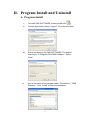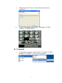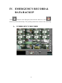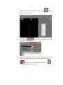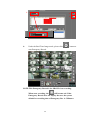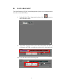
1
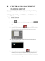
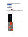
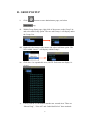
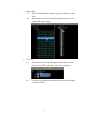
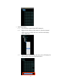
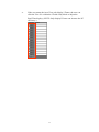
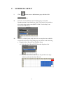
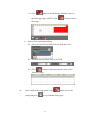
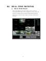
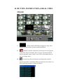
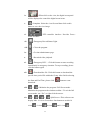
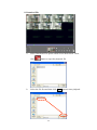
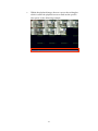
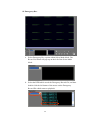
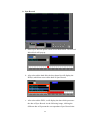
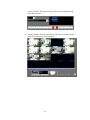
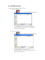
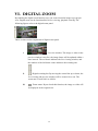
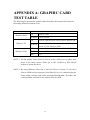
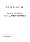
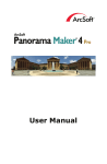
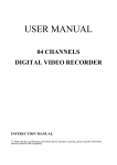
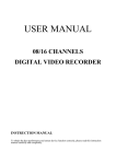
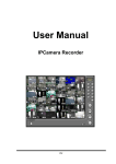
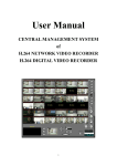
User Manual
CENTRAL MANAGEMENT SYSTEM
of H.264 DIGITAL VIDEO
RECORDER
1
TABLE of CONTENTS
I.
SYSTEM REQUIREMENTS .............................................................................3
A. MINIMUM REQUIREMENTS..................................................................3
B. SUGGESTED REQUIREMENTS .............................................................3
II. CENTRAL MANAGEMENT SYSTEM SETUP .............................................6
A. DVR SETUP .................................................................................................6
B. GROUP SETUP............................................................................................8
B. GROUP SETUP............................................................................................8
C. SCHEDULE SETUP..................................................................................12
D. SYSTEM SETUP .......................................................................................14
III. REAL-TIME MONITOR ...............................................................................15
A. REAL-TIME IMAGE................................................................................15
B. BUTTON INSTRUCTION of REAL-TIME IMAGE ............................16
IV. EMERGEMCY RECORD & DATA BACKUP ..............................................18
A. EMERGENCY RECORD .........................................................................18
B. DATA BACKUP .........................................................................................21
V. VIDEO PLAYBACK .........................................................................................23
A. VIDEO PLAYBACK..................................................................................23
B. EXPERT IMAGE.......................................................................................31
B. EXPERT IMAGE.......................................................................................31
VI. DIGITAL ZOOM...............................................................................................32
APPENDIX A: GRAPHIC CARD TEST TABLE ..................................................33
2
PREFACE
DVR Central Management System (CMS) is a 16 views recording software
which specific supports our H.264 DVR (Digital Video Recorder). This
software can provide real-time monitor, record the video on PC and then
playback the recorded video to the user.
Moreover, the user can also setup the software recording method for the
specific circumstances and performs video playback via Time and Event
Search.
I.
SYSTEM REQUIREMENTS
A. MINIMUM REQUIREMENTS
i.
ii.
iii.
iv.
CPU: Intel Pentium 4 2.0G
Memory: 512MB
VGA card: 128MB
Monitor Resolution: 1280 x 1024, 1024 x 768 (This user manual
is made by 1280 x 1024 resolution.)
v.
OS: Windows XP / 2000
B. SUGGESTED REQUIREMENTS
i.
ii.
iii.
iv.
v.
CPU: Intel Pentium D 3.2G or higher
Memory: 1024MB or higher
VGA card: 256MB or higher ( ATI chipset suggested)
Monitor Resolution: 1280 x 1024, 1024 x 768.
OS: Windows XP / 2000
3
II. Program Install and Uninstall
A. Program Install
i.
To install CMS SOFTWARE, please double click
ii.
License Agreement. Select “I Agree”, Go to the next step.
iii.
Select the directory for CMS SOFTWARE. The default
directory is "C:\Program Files\CMS Software ". Select
“Next”.
iv.
.
Set up the name of the program folder. The default is “ CMS
Software ”. Click “Install” to start the installation.
4
v.
When finish, click “Close” to close the procedure of the
installation.
vi.
To start the program, select “Start” Æ”Program”Æ””CMS
Software ”Æ”CMS Software”.
B. Uninstall
i.
To uninstall the program, select “Start” Æ ”Program” Æ”CMS
Software”Æ ”Uninstall” to remove the program.
5
II. CENTRAL MANAGEMENT
SYSTEM SETUP
Please setup Central Management System step by step according to the following
instructions.
NOTE: Select “Start” Æ ”Program” Æ”CMS Software”Æ ”CMS Software” to
operate CMS software.
A. DVR SETUP
i.
Click
button to enter administrator page, and select
tag.
ii.
Among DVR Setup page, click
button to add DVR, and then
fill in the information about the DVR(s) which is going to connect.
iii. After finish adding DVR(s), DVR LIST block will display the new
DVR(s) which just add.
iv.
After complete the above setting, click
button to perform the
connection. If it is success for connection, the screen will pop-up the
success information dialog box. (However, if it is failure for connection,
6
the screen will pop-up the failure information dialog box.)
NOTE: If the user wants to delete the connected DVR, select the DVR first
and then click
v.
button to delete the DVR.
If the connected camera within the DVR List includes PTZ function,
PTZ preset point can be setup via operating PTZ block. The operating
steps are presented in the following,
a.
Spread up the DVR within the DVR List, double-click the camera
which includes PTZ function.
b.
Click the drop down list of preset point and change the name of it.
c.
Then, use the navigation key to adjust the preset point position.
d.
Finally, click the preset point button to complete the setting.
7
B. GROUP SETUP
i.
Click
button to enter administrator page, and select
tag.
ii.
Within Group Setup page, right click of the mouse on the Group List
and select Add Group option. The new add Group 1 will display under
the Group List.
iii. Right-click the button of the mouse and select Add Area option. The
New Added “Area 1” will display within Group 1.
iv. Click Area 1 to expand this area. (NOTE: Each area can display 16
views.)
v.
Finally, add the DVR channel into the new created Area. There are
“Mouse Drag”, “View All” and “Individual Select” three methods.
8
a. Mouse Drag
a-1. Select the DVR channel which is going to add into the Area
View.
a-2. Drag the mouse from the selected channel to the Area view.
As the following example,
b. View All
b-1. Select the Area first and then right-click the button of the
mouse on the DVR. After that, select View All option.
b-2.
Click the Area which is mentioned above and it will display
all 16CH of DVR.
9
c. Individual Select
c-1. Click DVR to expand all the DVR channels。
c-2.
Right click the button of the mouse to select the channel
which is going to add to the Area, and select the display
view of the Area.
c-3.
After complete the selection, the Area view will display the
DVR channel which just mentioned above.
10
v.
If the user wants the Area View only display I Frame, the user can
click the View No. within the I Frame Only block to adjust the
Real-Time display. (NOTE: Only display I Frame can increase the PC
efficiency.)
11
C. SCHEDULE SETUP
i.
Click
button enter to administrator page and then click
tag.
ii.
Select the record path when operate Emergency record and
Synchronization record. Moreover, click “Use Overlay” to decide to
use overlay play mode or not (NOTE: Click “Use Overlay” can
increase PC efficiency.).
iii.
Moreover, within system setup, the user can setup the time schedule
of Sync Record as well. The setting steps are shown in the following,
a. Regularly Sync Record Time Schedule Setup
a-1. Select the Sync Record DVR from the drop down list.
a-2. Left-click the button of the mouse and pull the time range
which is performed the Sync Record.
12
a-3. Click
button to finish the time schedule setup. As
the following image, (NOTE: Click
the setup.)
b.
button to cancel
Special-Time Sync Record Setup
b-1. Select the Sync Record DVR from the drop down list.
b-2. Select the Start and End Time of the DVR.
b-3. Click
button to finish special-time setup. As the
following image,
iv.
After complete the setup, please click
setting and press
button to save the
to exit Schedule Setup page.
13
D. SYSTEM SETUP
i.
Click
button enter to administrator page and then click
tag.
ii.
After entry to the system setup page, the “Use Overlay” and “Auto
Adjust Resolution” two options are provided.
a.
b.
Use Overlay: Select “Use Overlay” can increase PC efficiency.
Auto Adjust Resolution: Select “Auto Adjust Resolution” can
alter the screen resolution automatically. (NOTE: if the PC screen
supports 1280*1024 resolution, the screen will adjust to
1280*1024 and CMS software will adjust to 1280*1024 screen
resolution automatically after “Auto Adjust Resolution” is
selected. However, if the PC screen does not support 1280*1024,
the screen will adjust to 1024*768 and CMS software screen
will adjust to 1024*768 resolution automatically.)
c.
iii.
Default Screen Split: The number of split screen which will
display when CMS software is operated in the beginning.
After complete the setup, please click
and press
to exit System Setup page.
14
button to save the setting
III. REAL-TIME MONITOR
A.
REAL-TIME IMAGE
DVR Central Management System (CMS) is software which can
control Multi-DVRs. Due to CMS is designed by “Group” concept, the
software can combine different channels within different DVRs into
ONE Group to perform real-time monitor. The image is shown in the
following:
15
B. BUTTON INSTRUCTION of REAL-TIME
IMAGE
i.
ii.
: When connected DVR has triggered events, these
triggered events will be presented within this block.
: Double-click the left button of the mouse on the triggered
event of the Event List block, the live image will be transferred
into the playback mode of this event. Click on this button back to
the Live Image mode.
iii.
: System Log. Press this button can display the software
system log which is including CMS start and close time and so on.
The system log example is shown as follows,
16
iv.
: When click on the view, the digital zoom panel
will be displayed to control the digital zoom in/out.
v.
: Snapshot. Select the view first and then click on this
button to save the view image.
vi.
: PTZ controller interface. Provides Focus、
Zoom and IRIS.
vii.
: Emergency Record Status Light.
viii.
: Close the program.
ix.
: Get into administrator page.
x.
: Recorded video playback
xi.
: Emergency REC.。Click this button to start recording
immediately in emergency situation. To stop recording, please
click the button again.
: Download the file. Click this button to download the
xii.
specific time period file within the Group. After finish selecting
the Start and End Time, please click
button to start
download
xiii.
/
: Minimize the program / Full Screen mode。
Minimize the program to the windows toolbar. / To exit the full
screen mode, use “Esc” or right-click the mouse.
xiv.
/
/
/
Split Screen : This software can
display Max. 16 views. Press these four buttons to switch 16
views
, 9 views
, 4 views
17
and 1 view
。
IV. EMERGEMCY RECORD &
DATA BACKUP
button to enter Emergency Record mode. Moreover, click
Click
button to perform data backup. The operating instruction is shown in the following.
A.
EMERGENCY RECORD
18
i.
Before operate Emergency Record, please click
button to
enter administrator page.
ii.
Then, select
As the following image,
iii.
Click on the drop down list of 1. Record Path block to select the
HDD to save the Emergency Record file. After that, click on
2.
tag to enter to schedule setup page.
button to save the setting. Finally, click on 3.
button to exit System Setup page.
19
1.
2.
3.
iv.
Under the Real-Time Image mode, please click
button to
start Emergency Record.
NOTE: This Emergency Record is for GROUP view recording.
When start recording, the
will become red. If the
Emergency Record does not stop by the user, the system
default for recording time of Emergency Rec. is 5 Minutes.
20
B.
DATA BACKUP
The Data Backup of DVR Central Management System is to backup the data
from the connected DVR(s).
i.
Under the Real-Time Image mode, please click
enter Download page.
button to
ii. Click DVR drop down list to select the backup DVR and then, it
will display the DVR recorded time period on its right hand side.
iii. Select the Start and End backup time.
21
iv. Click
button to select data saved folder and then click
to start backup.
NOTE: 1. If the user wants to stop backup immediately during
the backup period, please click
button to
stop it.
2. Each backup file will be named as START TIME.
For example:
(20080630154009.264)
3. Click “Backup R6Viewer” option can download R6
Viewer software.
4. The downloaded *.264 file has to be played by CMS
software and R6 Viewer software. It has not
supported by other media player.
22
V. VIDEO PLAYBACK
Please click
to enter Video Playback mode.
A. VIDEO PLAYBACK
Please select the Video Playback mode. There are DVR Search,
Download File and Emergency Rec. three playback modes. For the
following image,
23
i. DVR Search
a.
Under the DVR Search playback mode, move the mouse to the
right of the screen. SEARCH TOOL will pop-up. For the
following example,
b.
Select the DVR first, then it will display the recording time of the
selected DVR.
24
c.
After selected the playback DVR, video playback will be operated
by doing Event Search and Time Search.
c-1. Event Search
c-1-1. Select the playback HDD of DVR
.
c-1-2. After selected the HDD, it will display all trigger
events to the following table. Double-click the left
button of the mouse on the trigger event. For the
following example,
c-1-3. After finish the above setting, the playback screen
will play the selected event video.
c-2. Time Search
c-2-1. Please select the playback start time within the Time
Search block.
c-2-2.
After finish the time setting, please click
button to start video playback.
d.
Click
/
/
/
button to switch the
playback split screen 1 CH/ 4CH/ 9CH/ 16CH.
e.
Click
to stop playback. Moreover, click
to start
playback.
f.
Use
&
to fasten the forward and rewind playback
speed.(NOTE: Forward and Rewind playback only display I
Frame.)
25
ii. Download File
a.
Select Download File option within Select Mode block. Then,
click
b.
button to open the playback file.
Select the file first and then click Open button to start playback.
26
c.
Within the playback image, the user can use the seeking bar
which is under the playback screen to find out the specific
time-point. As the following example,
27
iii. Emergency Rec.
a. Select Emergency Rec. option within Select Mode block. The
Record List block will pop-up on the left of the Select Mode
block.
b. Select the HDD which saved the Emergency Record file, and then
double-click the left button of the mouse on the Emergency
Record file which wants to playback.
28
iv. Sync Record
a. Select Sync Record option within Select Mode block. The Record
Index block will pop-up.
b. After selected the hard disk, the drop down list will display the
DVR(s) which has reserved the data of Sync Record.
c. After selected the DVR, it will display the date which possesses
the data of Sync Record. As the following image, clicking the
different date will present the correspondence Sync Record time
29
period. (NOTE: The time period will become red while having
Sync Record data.)
d. Finally, double-click the left button of the mouse on the red time
period to perform the video playback.
30
B. EXPERT IMAGE
Image data can be export as JPG or AVI format.
i.
ii.
Export as JPEG format:
a.
Click
button. It will show the following dialogue box.
b.
The default filename will be named as “Img_channel_
yyyymmdd_hhmmss.jpg” format. The user can decide the
filename and the saving path.
Export as AVI format:
a.
Click
button. It will show the following dialogue box.
b.
The default filename will be named as “AVI_
yyyymmdd_hhmmss.avi” format. The user can decide the
filename and the saving path.
31
VI. DIGITAL ZOOM
By enabling the digital zoom function, user can zoom in/out the image to get proper
view. Digital zoom can be functionalized in live-viewing, playback viewing. The
following figures refer to the digital zoom panel.
There are three main components of digital zoom panel.
i.
:Preview window. The image or video in the
preview window is not live, the image frame will be updated within a
time interval. The red frame indicates the live-viewing window, and
the number of the left-down corner indicates the zooming rate.
ii.
:Digital zooming bar. By moving the control bar up or down, the
live-viewing and preview window will be zoomed in or out. The
zoom rate is from 100% to 1000%.
iii.
:Zoom status. By un-check this function, the image or video will
be displayed in the original size.
32
APPENDIX A: GRAPHIC CARD
TEST TABLE
The following list presents the graphic cards which have been tested with Network
Recording Software Premium series.
OS
Windows 2000
ATI
NVIDIA GEFORCE 6200
ATI
RADEON 9200, RADEON 9550, RADEON XPRESS 200
NVIDIA
GEFORCE 6200, GEFORCE 6600, GEFORCE 7100,
GEFORCE 7300, GEFORCE 8500
ATI
RADEON XPRESS 200M, RADEON HD 2400 PRO
Windows XP
Windows Vista
RADEON 7500
NVIDIA GEFORCE 8500
Intel
G33
NOTE 1: All the graphic cards which are shown in above table have to update their
driver to the latest version. Please go to ATI, NVIDIA or Intel official
website to update the driver.
NOTE 2: By using Windows Vista, due to Intel G33 Driver (Version: 7.14.10.1461)
from its OEM have not supported Vista DirectX 10 yet, it cannot display the
image within Overlay mode while operating Dual-Monitor. Therefore, this
caused problem still wait for the solution from its OEM.
33