1
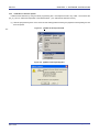
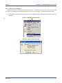
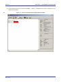
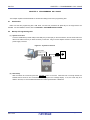
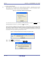
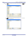
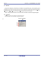
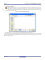
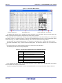
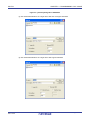
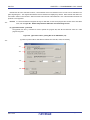
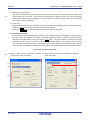
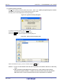
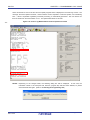
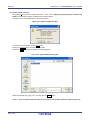
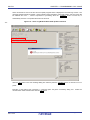
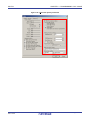
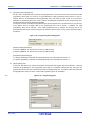
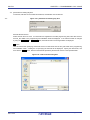
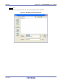
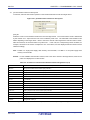
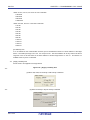
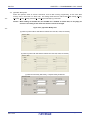
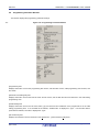
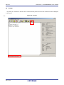
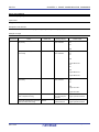
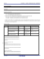
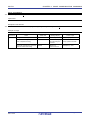
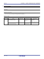
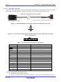
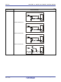
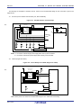
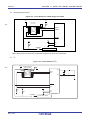
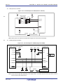
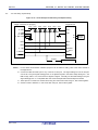
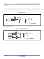
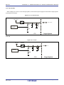
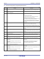
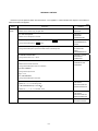
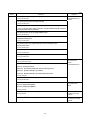
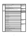
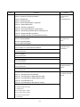
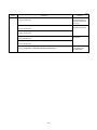
(7/8) Edition 5th edition Description Applied to Change of the following figures CHAPTER 5 EXAMPLE Figure 5-2. [Setup host connection] Command OF OPERATION Figure 5-5. Main Window USING PROGRAMMING GUI Figure 5-6. [Setup] Command Figure 5-7. Device Setup Dialog Box - [Target] Tab Figure 5-12. [Object HEX file] Area Figure 5-13. Selection of Program File Figure 5-15. Device Setup Dialog Box - [Advanced] Tab Figure 5-16. Downloading of PR5 File, ESF File and Program File Figure 5-17. [Autoprocedure(E.P.)] Command Figure 5-18. [Autoprocedure(E.P.)] Command Execution Result Change of the following tables CHAPTER 6 USAGE Table 6-1. [Commands] Menu IN STANDALONE MODE Table 6-2. [Type Setting] Menu Table 6-3. [Option Setting] Menu 8.2 Command List CHAPTER 8 USAGE Change of Table 8-2. List of FP5 Device Commands COMMUNICATION COMMANDS 8.5.13 read command Change of description 8.5.14 scf command Change of description Addition of 8.5.16 slb command 8.5.17 sum command Change of description 9.4.1 Target Cable (16-pin type) CHAPTER 9 Change of description CONNECTORS AND CABLES 9.4.2 Target Cable (14-pin type) Change of description Change of the following figures CHAPTER 10 NOTES Figure 10-1. SIO-H/S Interface Circuit Example ON TARGET SYSTEM DESIGN Figure 10-2. Circuit Example for 78K0S (Single-wire UART) Figure 10-3. Circuit Example for 78K0R (Single-wire UART) Figure 10-4. Circuit Example for I2C Figure 10-5. Circuit Example for 78K0 (TOOLCx, TOOLDx) Addition of the followings <6> V850E2 (Single-wire UART) <7> V850E2 (CSI) <8> RL78 family (VDD = EVDD) <9> RL78 family (VDD ≠ EVDD) <10> RX family, SuperH family <11> R8C family C-7