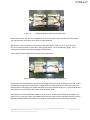
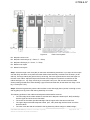
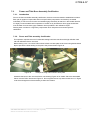
1
GTR9-9-07 Flex PLI GTR User Manual 133-9900 User Manual FLEX PLI GTR Rev F (Draft) ©2013 Humanetics Innovative Solutions Page 1 of 103 GTR9-9-07 For information on Humanetics products, please visit our web site at www.humaneticsatd.com or contact: Humanetics Innovative Solutions 47460 Galleon Drive Plymouth, MI 48170, USA Telephone: (+1) 734-451-7878 Fax: (+1) 734-451-9549 No part of this publication may be reproduced, stored in a retrieval system or transmitted in any form or by any means, electronic, photocopying, recording, mechanical or otherwise, without the express written consent of Humanetics Innovative Solutions. Copyright © 2013 Humanetics Innovative Solutions. All rights reserved. The information in this manual is furnished for informational use only, and is subject to change without notice. Humanetics Innovative Solutions assumes no responsibility or liability for any errors or inaccuracies that may appear in this manual. 133-9900 User Manual FLEX PLI GTR Rev F (Draft) ©2013 Humanetics Innovative Solutions Page 2 of 103 GTR9-9-07 Table of Contents Section 1. Introduction .............................................................................................................................. 10 1.1 Overview.......................................................................................................................................... 10 1.2 Tools and Recommended Spares ................................................................................................... 11 Section 2. Instrumentation ........................................................................................................................ 16 2.1 Standard 12 Channel instrumentation ............................................................................................. 16 2.2 Optional instrumentation ................................................................................................................. 16 2.3 ISO MME Codes ............................................................................................................................. 22 2.3.1 Co-ordinate System ................................................................................................................ 25 2.3.2 Signal Polarity, Sensor function check ................................................................................... 26 2.3.3 Filter Class .............................................................................................................................. 26 2.4 Data Acquisition Options ................................................................................................................. 27 2.5 Off Board DAS ................................................................................................................................. 27 2.6 Messring M=BUS On Board Data Acquisition ................................................................................. 29 2.6.1 M=BUS description ................................................................................................................. 29 2.6.2 24 Channel M=BUS ................................................................................................................ 31 2.7 DTS Onboard SLICE Nano DAS ..................................................................................................... 33 2.7.1 SLICE 24 Channel Option ...................................................................................................... 37 2.7.2 Electrical Interference ............................................................................................................. 37 2.8 DTI Hentschel Onboard DAS .......................................................................................................... 38 2.8.1 2.9 KT MicroDAU Onboard DAS ........................................................................................................... 40 2.9.1 2.10 MicroDAU Description ............................................................................................................ 40 Kyowa 6 Das System ...................................................................................................................... 43 Section 3. 3.2 DTI Description ....................................................................................................................... 38 Disassembly and Assembly ..................................................................................................... 47 Femur Exploded View ..................................................................................................................... 50 3.2.1. Femur Disassembly ................................................................................................................ 52 3.2.2. Femur (Upper Leg) Assembly................................................................................................. 52 3.2.3. Femur assembly after static certification ................................................................................ 57 3.3 Knee Exploded View ....................................................................................................................... 58 3.3.1. Knee Disassembly .................................................................................................................. 59 133-9900 User Manual FLEX PLI GTR Rev F (Draft) ©2013 Humanetics Innovative Solutions Page 3 of 103 GTR9-9-07 3.3.2. Knee Assembly ....................................................................................................................... 59 3.3.3. Assembly After Certification.................................................................................................... 62 3.4 Tibia Exploded View ........................................................................................................................ 63 3.4.1. Tibia Disassembly ................................................................................................................... 65 3.4.2. Tibia Assembly ....................................................................................................................... 65 3.4.3. After Calibration ...................................................................................................................... 68 3.4.4. Fitting flesh and Covers .......................................................................................................... 68 3.4.5. Flesh Disassembly .................................................................................................................. 72 Section 4. Maintenance ............................................................................................................................ 73 4.1 Introduction ...................................................................................................................................... 73 4.2 General External Damage inspection ............................................................................................. 73 4.3 Support Roller.................................................................................................................................. 73 4.4 Red Neoprene Suit Covers ............................................................................................................. 73 4.5 Protective Plastic End Covers (Part 133-5516)............................................................................... 73 4.6 Tibia and Femur .............................................................................................................................. 74 4.6.1. Assembly Segment Play ......................................................................................................... 74 4.6.2. Buffers between segments ..................................................................................................... 74 4.6.3. Shoulder Bolt and Segment Screw Tightness Check ............................................................. 74 4.7 Knee ................................................................................................................................................ 74 4.7.1. Knee Meniscus ....................................................................................................................... 74 4.7.2. Knee spring cables and bone stopper cables......................................................................... 74 4.8 Sensor and Electrical Maintenance ................................................................................................. 75 4.8.1. General Electrical Maintenance .............................................................................................. 75 4.8.2. Bone Maintenance .................................................................................................................. 75 4.8.3. String Potentiometer Maintenance ......................................................................................... 75 Section 5. Storage .................................................................................................................................... 76 Section 6. Weight Specification ................................................................................................................ 76 Section 7. Calibration and Certification Testing ........................................................................................ 77 7.1. Calibration and Certification Overview ............................................................................................ 77 7.2. Femur and Tibia Bone Assembly Certification ................................................................................ 78 7.2.1. Introduction ............................................................................................................................. 78 133-9900 User Manual FLEX PLI GTR Rev F (Draft) ©2013 Humanetics Innovative Solutions Page 4 of 103 GTR9-9-07 7.2.2. 7.3. Femur and Tibia assembly Certification ................................................................................. 78 Knee Certification ............................................................................................................................ 83 Section 8. Pendulum Dynamic Certification.............................................................................................. 85 8.1 Introduction ...................................................................................................................................... 85 8.2 Pendulum Rig Assembly Instruction ............................................................................................... 86 8.3 Leg Preparation for Pendulum Dynamic Certification ..................................................................... 89 8.4 Pendulum Rig Preparation .............................................................................................................. 92 8.5 Running a test ................................................................................................................................. 93 8.6 Data Processing .............................................................................................................................. 94 8.7 Pendulum Femur Corridors ............................................................................................................. 94 Section 9. Dynamic Inverse Certification Test .......................................................................................... 94 9.1 Introduction ...................................................................................................................................... 94 9.2 Inverse Test Description.................................................................................................................. 95 9.3 Preparation of the Inverse Test set up ............................................................................................ 95 9.4 Impactor Friction, Stroke Phases and Speed Measurement .......................................................... 96 9.5 Leg Preparation of the leg for Dynamic Inverse Test ...................................................................... 97 9.6 Running a Dynamic Inverse Test .................................................................................................... 98 9.7 Data Processing .............................................................................................................................. 99 9.8 Inverse Femur Corridors ................................................................................................................. 99 Section 10. Vehicle Test ........................................................................................................................... 100 10.1 Introduction .................................................................................................................................... 100 10.2 Leg Preparation for car test ........................................................................................................... 101 10.3 Injury Thresholds ......................................................................................................................... 1011 10.4 Leg loading limits in free flight ....................................................................................................... 101 10.5 Catch rope ..................................................................................................................................... 102 10.6 Impact pusher plate………………………………………………………………………………………102 133-9900 User Manual FLEX PLI GTR Rev F (Draft) ©2013 Humanetics Innovative Solutions Page 5 of 103 GTR9-9-07 Table of Figures Figure 1 . T-Handle Wrenches ............................................................................................................. 11 Figure 2 . Hex Wrenches ..................................................................................................................... 12 Figure 3 . Ratchet offset wrench with hex bits kit ................................................................................ 12 Figure 4 . Leg wire setting tool 133-5112............................................................................................. 13 Figure 5 . Knee spacer tool 133-5113.................................................................................................. 13 Figure 6 . Tibia and Femur base tool 133-8114 or 133-8129 .............................................................. 13 Figure 7 . Optional Instrumentation for Femur ..................................................................................... 17 Figure 8 . Detail A, Exploded View, upper and lower knee 133-7507 ................................................. 18 Figure 9 . Wire routing for Detail A optional sensors 133-7507 ........................................................... 18 Figure 10 . Wire routing out of segment for optional sensors Detail A in upper knee ........................... 19 Figure 11 . Similar arrangement to Detail A, but with 2 uniax Kyowa accels. Assembly 133-7600 ...... 19 Figure 12 . Sensor IES 3103 ARS example locations, knee lower. ....................................................... 20 Figure 13 . Kyowa accel 3 axis option for leg top and bottom locations, (mount 133-7530) ................. 20 Figure 14 . Optional Instrumentation, for Tibia ...................................................................................... 21 Figure 15 . Leg Local Sign Convention .................................................................................................. 25 Figure 16 . Leg manipulations for positive output .................................................................................. 26 Figure 17 . Clamping Arrangement and Position for Off board Wires ................................................... 27 Figure 18 . Off Board wiring left hand side of impact face ..................................................................... 28 Figure 19 . Off Board wiring right hand side of impact face ................................................................... 28 Figure 20 . Wiring Diagram for 12 channel M=BUS............................................................................... 29 Figure 21 . M=BUS arrangement in knee 12 channels LH side to impact direction .............................. 30 Figure 22 . M=BUS arrangement 12 channels RH side of impact direction .......................................... 30 Figure 23 . Clamping of M=BUS Disconnect Connector ....................................................................... 30 Figure 24 . M=BUS Terminator housing installation in upper knee ....................................................... 31 Figure 25 . Fixing M=BUS Wire to Launcher ......................................................................................... 31 Figure 26 . Right hand side of knee M=BUS 24 channels, sensors not connected .............................. 32 Figure 27 . Top right hand side of knee M=BUS 24 channels, sensors connected ............................... 32 Figure 28 . Bottom right hand side of knee M=BUS 24 channels, sensors connected ......................... 32 Figure 29 . Top left hand side of knee Messring 24 channels sensors connected ................................ 33 Figure 30 . Bottom left hand side of knee M=BUS 24 channels, sensors connected............................ 33 Figure 31 . Wiring diagram for 12 channel SLICE ................................................................................. 34 Figure 32 . Typical 12 channel Slice wiring to knee ............................................................................... 34 Figure 33 . SLICE disconnect connector ............................................................................................... 35 Figure 34 . LH of leg with knee covers fitted 12 channels. Leg wires are not shown secured. ............. 35 Figure 35 . SLICE Right hand side of knee 12 channels showing connectors ..................................... 36 133-9900 User Manual FLEX PLI GTR Rev F (Draft) ©2013 Humanetics Innovative Solutions Page 6 of 103 GTR9-9-07 Figure 36 . Leg with disconnect wire, TDAS interface and power supply.............................................. 36 Figure 37 . Optional SLICE unit 24 channel option (right side).............................................................. 37 Figure 38 . Left side wiring example of 24 channel SLICE .................................................................... 37 Figure 39 . DTI DAS left hand side of knee showing Di Mod hubs ........................................................ 38 Figure 40 . DTI DAS right hand side of knee showing crash recorder on the left and DiMod hub on the right. ....................................................................................................................................... 39 Figure 41 . DTI DAS General Overview ................................................................................................. 39 Figure 42 . Exploded view of knee showing Micro Dau integration ....................................................... 40 Figure 43 . Showing drawing of Micro Dau part numbers ...................................................................... 41 Figure 44 . Right hand side of impact face, lower covers removed ....................................................... 41 Figure 45 . Left hand side of impact face, covers fitted ......................................................................... 42 Figure 46 . Schematic layout of 12 channel Micro Dau ......................................................................... 42 Figure 47 . Kyowa 12 Channel System Configuration Diagram ............................................................ 43 Figure 48 . Kyowa Side in 12ch ............................................................................................................. 44 Figure 49 . Kyowa Rear Side in 12ch .................................................................................................... 44 Figure 50 . Kyowa Disconnect Connector.............................................................................................. 45 Figure 51 . Kyowa Front side in 24ch .................................................................................................... 45 Figure 52 . Kyowa Rear side in 24ch ..................................................................................................... 46 Figure 53 . Leg assembly, Exploded View ............................................................................................. 47 Figure 54 . Screws to be tightened to 8 Nm non impact side ................................................................ 49 Figure 55 . Femur Assembly, Exploded View ........................................................................................ 50 Figure 56 . 133-8129 base with 133-5514 segment and bone clamps inside ....................................... 54 Figure 57 . 133-8129 base with 133-5514 segment, bone clamps and bone assembly ....................... 55 Figure 58 . Fitting and tightening first blue segment .............................................................................. 55 Figure 59 . Fitting thin bone spacer with captive shim ........................................................................... 56 Figure 60 . Bone exit cable restraint use cable ties (ties not shown trimmed or tightened) .................. 57 Figure 61 . Knee Assembly, Exploded View .......................................................................................... 58 Figure 62 . Meniscus string pot assembly wire feed .............................................................................. 60 Figure 63 . Meniscus with all string pots assembled. String pots identified........................................... 61 Figure 64 . Meniscus wire clamp ........................................................................................................... 61 Figure 65 . Attachment plate, crimp wires in tension with spacers ready for knee femur block assembly ............................................................................................................................................. 62 Figure 66 . Cross wire feed through on knee ......................................................................................... 62 Figure 67 . Tibia Assembly, Exploded View........................................................................................... 63 Figure 68 . Typical shim arrangement with .05 shim inside captive shim .............................................. 67 Figure 69 . Assembly of last two segments on tibia ............................................................................... 68 Figure 70 . Flesh Cover System ............................................................................................................ 69 Figure 71 . Assembly of first flesh layer ................................................................................................. 70 133-9900 User Manual FLEX PLI GTR Rev F (Draft) ©2013 Humanetics Innovative Solutions Page 7 of 103 GTR9-9-07 Figure 72 . Zipper locations alternating on the sides (schematic cross section) ................................... 70 Figure 73 . Assembly of flesh second layer ........................................................................................... 71 Figure 74 . Rubber flesh assembly Velcro positions .............................................................................. 71 Figure 75 . Rubber flesh tied on with Velcro .......................................................................................... 71 Figure 76 . Leg with outer cover fitted.................................................................................................... 72 Figure 77 . String potentiometer pull wire length ±1mm ........................................................................ 75 Figure 78 . Example of fixing Teflon sheet to base plate ....................................................................... 78 Figure 79 . Bone and knee fixture 133-8120 for static assembly bending test femur shown ................ 79 Figure 80 . Static certification fixture 133-8120 showing knee .............................................................. 80 Figure 81 . Bone Assembly Fixture (femur shown under bending)........................................................ 81 Figure 82 . Femur assembly certification corridor moment vs. deflection showing typical results ........ 82 Figure 83 . Tibia assembly certification corridor moment vs. deflection showing a typical results ........ 82 Figure 84 . Knee Certification Fixture .................................................................................................... 83 Figure 85 . Figure MCL sensor elongation Upper and lower corridor .................................................... 84 Figure 86 . Figure ACL and PCL upper and lower corridors.................................................................. 84 Figure 87 . Diagram of Dynamic Pendulum Fixture ............................................................................... 85 Figure 88 . Exploded view Dynamic Rig part nr 133-8400 .................................................................... 87 Figure 89 . Check screws with 8 Nm torque .......................................................................................... 89 Figure 90 . Stop cable clearance adjustment using setting tool ............................................................ 90 Figure 91 . Recommended method to align knee to remove any twist and shear................................. 90 Figure 92 . Attaching Pendulum Ballast Weight .................................................................................... 91 Figure 93 . Attaching Pendulum Rig Pivot hinge ................................................................................... 91 Figure 94 . Checking the Impact Block position adjustment .................................................................. 92 Figure 95 . Examples of release latches ................................................................................................ 93 Figure 96 . Diagram of Dynamic Inverse Certification Test set up ........................................................ 95 Figure 97 . Paper cloth wrapping of honeycomb ................................................................................... 96 Figure 98 . Launch guide with 15° tilt toward guided impactor .............................................................. 98 Figure 99 . Optional catch rope bracket 133-5034 .............................................................................. 102 Figure 100 . Impactor guide width setting 113mm ............................................................................. 102 Figure 101 . Humanetics Launch plate Part Nr 133-8200 (Aluminum and Carbon Fiber) ................. 103 133-9900 User Manual FLEX PLI GTR Rev F (Draft) ©2013 Humanetics Innovative Solutions Page 8 of 103 GTR9-9-07 Table List Table 1. Contents of the tool kit provided with the leg on delivery. ....................................................... 14 Table 2. Screw abbreviations ................................................................................................................ 14 Table 3. Torque Requirements .............................................................................................................. 14 Table 4. Spare Parts List ....................................................................................................................... 15 Table 5. 12 Channel Instrumentation..................................................................................................... 16 Table 6. Example of Optional Instrumentation Parts List ...................................................................... 21 Table 7. ISO MME Sensor Code table .................................................................................................. 24 Table 8. Wire label codes for all sensors ............................................................................................... 25 Table 9. Flex PLI Parts List .................................................................................................................... 48 Table 10. Femur Assembly, Parts List ................................................................................................. 51 Table 11. Knee Assembly, Parts List ................................................................................................... 59 Table 12. Tibia Assembly, Parts List ................................................................................................... 64 Table 13. Flex PLI GTR Mass ............................................................................................................. 76 Table 14. FLEX-PLI-GTR certification steps........................................................................................ 77 Table 15. Parts List for static fixture 133-8120 .................................................................................... 80 Table 16. Pendulum Dynamic Rig Part List ......................................................................................... 88 Table 17. Pendulum test corridors, peak values within 250 ms after impact ...................................... 94 Table 18. Inverse test corridors, peak values within 50 ms after impact ............................................. 99 Table 19. Threshold values for injury channels ................................................................................. 101 133-9900 User Manual FLEX PLI GTR Rev F (Draft) ©2013 Humanetics Innovative Solutions Page 9 of 103 GTR9-9-07 Section 1. Introduction 1.1 Overview Pedestrian Lower Legform Impactors are used to evaluate pedestrian protection afforded by passenger vehicles in case of vehicle collision with a pedestrian. The current EEVC WG17 Pedestrian lower legform impactor is known to have certain limitations regarding the biofidelity and the repeatability of the test results. Therefore, Japan proposed to use a completely new legform, the so-called Flexible Pedestrian Legform Impactor (FlexPLI). In the year 2000, the Japan Automobile Manufacturers Association, Inc. (JAMA) and the Japan Automobile Research Institute (JARI) initiated development of the “Flexible Pedestrian Leg form Impactor”. In 2002, an initial design was made available, followed by the Flex-GT version in 2006. The FLEX-PLI features biomechanically based femur, tibia and knee design, with biofidelic bending characteristics. In the knee the ligaments are represented according to human anthropometry. A Technical Evaluation Group (FLEX-TEG), consisting of governmental and industrial parties evaluated the possibility to use the leg form impactor for Global Technical Regulation on Pedestrian Safety (PS-GTR). Humanetics was a member of this group as dummy manufacturer and was asked to review the GT design and manufacture the leg. This review highlighted a number of improvements and the proposed GTR design was accepted. The performance of the leg was intended to remain the same to ensure existing test data was still valid. The components of the leg consist of a segmented femur with a suspension bracket at the top, a knee consisting of two aluminium blocks connected together with wires and springs, a segmented tibia as per the femur and a flesh system of rubber sheet and Neoprene. The main improvements were centralising the knee ligament deflection sensors to avoid impact direction sensitivity, balancing the spring force load in the knee joint to reduce knee joint twist about vertical axis, various improvements related to handling and repeatability, introduction of full bridge strain gauge configuration, additional optional sensors and incorporating on board Data Acquisition Systems (DAS) to improve free flight stability. Humanetics also reviewed the quasi static calibration procedures for internal bones, thigh, knee and lower leg assemblies. The pendulum dynamic calibration rig and procedure were also updated to provide more realistic loading. The high speed inverse linear guided impactor test is also a requirement for the GTR 9 regulation. The standard leg instrumentation has 12 channels; this includes 3 full bridge strain gage sensors in the thigh and 4 in the lower leg all measuring leg bending moments, an accelerometer and 4 string potentiometers in the knee, each one measures specific ligament elongation. There are also options for a further 26 linear accelerometer channels and 9 Angular Rate Sensors (ARS). Flex GTR has symmetric design so can represent a right or left leg. The manual structure is as follows:- Tools / Standard Instrumentation / Optional Instrumentation / ISO Codes / DAS Options / Disassembly and Assembly / Maintenance / Storage / Weight Spec / Calibration and Certification / Leg Preparation for Dynamic Testing and Car Test Information. 133-9900 User Manual FLEX PLI GTR Rev F (Draft) ©2013 Humanetics Innovative Solutions Page 10 of 103 GTR9-9-07 1.2 Tools and Recommended Spares Several types of standard tools are used in the assembly and disassembly of the dummy. T-handle wrenches (Figure 1) and hex wrenches (Figure 2) can be used to access most of the fasteners in the dummy. In some cases, access to fasteners is easier if a ratchet offset wrench with hex bits is used (Figure 3). Figure 1 . T-Handle Wrenches 133-9900 User Manual FLEX PLI GTR Rev F (Draft) ©2013 Humanetics Innovative Solutions Page 11 of 103 GTR9-9-07 Figure 2 . Figure 3 . Hex Wrenches Ratchet offset wrench with hex bits kit An 8, 4 mm and 1/8”open ended wrenches are required. A wire spacer tool 133-5112 is needed see Figure 4 to set bone assembly wire stopper clearance and there is another spacer tool to space the knee string potentiometer attachment part 133-5113 for knee assembly. See Figure 5. Two of these are used to hold string potentiometer attachment plate in position on assembly. All these tools along with 133-8129 figure 6, are provided with the leg as part of the tool box. 133-9900 User Manual FLEX PLI GTR Rev F (Draft) ©2013 Humanetics Innovative Solutions Page 12 of 103 GTR9-9-07 Figure 4 . Figure 5 . Figure 6 . Leg wire setting tool 133-5112 Knee spacer tool 133-5113 Tibia and Femur base tool 133-8129 133-9900 User Manual FLEX PLI GTR Rev F (Draft) ©2013 Humanetics Innovative Solutions Page 13 of 103 GTR9-9-07 Note: Apart from the string potentiometer #2-56 UNC cap head screws and the ARS optional angular rate sensors which use #0-80 cap heads all the leg screws are metric. PART NO. 6002565 6002558-13 5000522 133-5112 5000819 9003192 133-5113 133-5025 133-8129 Table 1. QTY 1 25 meter roll 20 1 1 1 2 10 1 DESCRIPTION Transport Case Double Sided Tape, 50mm Wide M5 Nyloc Nuts Wire Setting Tool Open Ended Wrench, 4mm Open Ended Wrench, 1/8” Setting Tool, Knee Double Sided Tape, Impact Segment Bone base assembly tool Contents of the tool kit provided with the leg on delivery. Note: A strong double sided tape is used extensively on the Flex leg. Humanetics recommends the use of this tape or a tape with the same strength to maintain performance. 1.3 Screw Abbreviations ABBREVIATION SHCS BHCS FHCS SHSS MSSFP DESCRIPTION Socket Head Cap Screw Button Head Cap Screw Flat Head Cap Screw Socket Head Shoulder Screw Metric Socket Setscrew Flat Point Table 2. 1.4 Screw abbreviations Torque Requirements DESCRIPTION Leg attachment to knee front M8 BHCS Leg attachment to knee rear M8 MSSFP All segment M6 BHCS Shoulder link screws M10 Table 3. 133-9900 User Manual FLEX PLI GTR Rev F (Draft) ©2013 Humanetics Innovative Solutions TORQUE Nm 8 8 3 3 Torque Requirements Page 14 of 103 GTR9-9-07 1.5 Recommended Spares PART NO 133-5165 133-5365 133-5013 133-5014 133-5015 133-5016 133-5017 133-5516 61-503-05-01-00 61-507-05-01-00 61-503-05-01-00-MB QTY 1 1 1 1 1 1 2 1 1 1 1 61-507-05-01-00-MB 1 DESCRIPTION Femur bone assembly tested and certified Tibia bone assembly tested and certified Cover inner femur Cover inner femur Cover inner tibia Cover outer tibia Cover Flex PLI GTR End cover Cable assy 150 mm STR POT R to 7 pin male Cable assy 150 mm STR POT L to 7 pin male Cable assy 150mm STR POT R to 7 pin male 3.3 Volt DAS system only Cable assy 150mm STR POT L to 7 pin male 3.3 Volt DAS system only Table 4. 133-9900 User Manual FLEX PLI GTR Rev F (Draft) ©2013 Humanetics Innovative Solutions Spare Parts List Page 15 of 103 GTR9-9-07 Section 2. Instrumentation 2.1 Standard 12 Channel instrumentation FLEX-PLI-GTR is offered with 12 channel standard instrumentation, measuring tibia and femur bending moments and knee ligament elongations as well as acceleration in the knee bottom (knee tibia block) in impact direction. The standard instrumentation channels are listed in Table 5. The channels intended for injury assessment are the 4 tibia bending moments, knee Medial Collateral Ligament (MCL), Anterior Cruciate Ligament (ACL) and Posterior Cruciate Ligament (PCL) elongations. These channels are controlled by the certification procedures given in Sections 8 and 9. Corridors are also provided for the femur channels, See Table 18 section 8.7. These corridors are not a regulation requirement, they are a guide to advise on the expected performance of the femur. The accelerometer can be used for force calculation and the LCL provides information on elongation after rebound crossover of the knee. Instrument Channels Femur moment 1,2 and 3 Tibia moment 1,2,3 and 4 Knee bottom acceleration MCL elongation ACL elongation PCL elongation LCL elongation Table 5. 2.2 Purpose Injury Assessment Injury Assessment Injury Assessment Injury Assessment Total Standard 3 4 1 1 1 1 1 12 DAS Standard Option iDummy 12 Channel Instrumentation Optional instrumentation The FLEX-PLI offers a range of optional instrumentation for research purpose. Examples are using ARS for in flight stability and accelerometers for local force measurement. When running regulatory tests with optional instrumentation it is recommended to check that the total mass of the tool, including a certain amount of cable length, does not exceed the regulatory requirement. Each individual femur and tibia segment can be instrumented with a uniax accelerometer in impact direction. Tri-axial accelerometers and/or angular rate sensors are also available at various locations. It is recommended that damped accelerometers are used on FLEX PLI. 133-9900 User Manual FLEX PLI GTR Rev F (Draft) ©2013 Humanetics Innovative Solutions Page 16 of 103 GTR9-9-07 Figure 7 . Optional Instrumentation for Femur 133-9900 User Manual FLEX PLI GTR Rev F (Draft) ©2013 Humanetics Innovative Solutions Page 17 of 103 GTR9-9-07 Figure 8 . Figure 9 . Detail A, Exploded View, upper and lower knee 133-7507 Wire routing for Detail A optional sensors 133-7507 133-9900 User Manual FLEX PLI GTR Rev F (Draft) ©2013 Humanetics Innovative Solutions Page 18 of 103 GTR9-9-07 Figure 10 . Figure 11 . Wire routing out of segment for optional sensors Detail A in upper knee Similar arrangement to Detail A, but with 2 uniax Kyowa accels. Assembly 133-7600 There is also an alternate mirror image of 133-7600 available 133-7540 and for 133-7507 the mirrored mount is 133-7545 to route wires to the opposite side for DAS connection to prevent wires going around the knee thus avoiding wire damage and good wire routing. 133-9900 User Manual FLEX PLI GTR Rev F (Draft) ©2013 Humanetics Innovative Solutions Page 19 of 103 GTR9-9-07 Sensor IES 3103 ARS triax can be installed in the first segment from knee in the femur and tibia. The sensor bolts directly to the aluminium segment in each case. The sensor can also be mounted so that the cable can exit either side. See Figure 12. A special impact cover is required to accommodate the sensor. Figure 12 . Figure 13 . Sensor IES 3103 ARS example location, knee lower. Kyowa accel 3 axis option for leg top and bottom locations, (mount 133-7530) 133-9900 User Manual FLEX PLI GTR Rev F (Draft) ©2013 Humanetics Innovative Solutions Page 20 of 103 GTR9-9-07 Figure 14 . ITEM 1 2 2 3 4 5 6 7 8 QTY 1 6 8 1 1 1 1 3 6 PART NO. 133-7508 133-7514 133-7514 133-7507 133-7502 133-7516 5000164 IT-TBD 9003103 9 1 MS-68C 10 1 133-7506 Table 6. Optional Instrumentation, for Tibia DESCRIPTION ACCEL INSTRUMENTED OPTION LEG TOP & BOTTOM IMPACT SEGMENT - INSTRUMENTED ASSEMBLY (FEMUR) IMPACT SEGMENT - INSTRUMENTED ASSEMBLY (TIBIA) ACCEL & ARS INSTRUMENTED OPTION FOR KNEE KNEE END ACCEL MOUNT TAPE, DOUBLE SIDED SCREW, SHCS M2 X 0.4 X 18 DTS ANGULAR RATE SENSOR SCREW, SHCS #0-80 X 5/16 ACCELEROMETER, LINEAR TRIAXIAL, MEASUREMENT SPECIALTIES MS 68C SPECIAL M2 ACCEL FIXING Example of Optional Instrumentation Parts List 133-9900 User Manual FLEX PLI GTR Rev F (Draft) ©2013 Humanetics Innovative Solutions Page 21 of 103 GTR9-9-07 2.3 ISO MME Codes For the identification of sensor channels and for computer processing of signals the following codes have been established for ISO MME. No. 1 2 3 4 5 6 7 8 9 10 11 12 13 14 15 16 17 18 19 20 Location (Description) Femur Moment 3 Upper, X Femur Moment 2 Middle, X Femur Moment 1 Lower, X Knee LCL Elongation Knee ACL Elongation Knee PCL Elongation Knee MCL Elongation Tibia Moment 1 Upper, X Tibia Moment 2 Middle Upper, X Tibia Moment 3 Middle Lower, X Tibia Moment 4 Lower, X Knee Bottom Acceleration, Y Femur Top Acceleration, X Femur Top Acceleration, Y Femur Top Acceleration, Z Femur Segment 1 Acceleration, Y Femur Segment 2 Acceleration, Y Femur Segment 3 Acceleration, Y Femur Segment 4 Acceleration, Y Femur Segment 5 Acceleration, Y Category Test Object Position Transd Main Location Fine Location 1 Fine Location 2 Fine Location 3 Physical Dimension Direction Filter Class standard D 0 FEMR UP 00 PF MO X C standard D 0 FEMR MI 00 PF MO X C standard D 0 FEMR LO 00 PF MO X C standard D 0 KNEE LC 00 PF DS Z C standard D 0 KNEE AC 00 PF DS Z C standard D 0 KNEE PC 00 PF DS Z C standard D 0 KNEE MC 00 PF DS Z C standard D 0 TIBI UP 00 PF MO X C standard D 0 TIBI MI UP PF MO X C standard D 0 TIBI MI LO PF MO X C standard D 0 TIBI LO 00 PF MO X C standard D 0 KNEE BO 00 PF AC Y C additional D 0 FEMR TP 00 PF AC X C additional D 0 FEMR TP 00 PF AC Y C additional D 0 FEMR TP 00 PF AC Z C additional D 0 FEMR 01 00 PF AC Y C additional D 0 FEMR 02 00 PF AC Y C additional D 0 FEMR 03 00 PF AC Y C additional D 0 FEMR 04 00 PF AC Y C additional D 0 FEMR 05 00 PF AC Y C 133-9900 User Manual FLEX PLI GTR Rev F (Draft) ©2013 Humanetics Innovative Solutions Page 22 of 103 GTR9-9-07 21 22 23 24 25 26 27 28 29 30 31 32 33 34 35 36 37 38 39 40 41 Femur Segment 6 Acceleration, Y Knee Upper Acceleration, X Knee Upper Acceleration, Y Knee Upper Acceleration, Z Knee Upper Angular Rate, ωX Knee Upper Angular Rate, ωY Knee Upper Angular Rate, ωZ Knee Lower Acceleration, X Knee Lower Acceleration, Y Knee Lower Acceleration, Z Knee Lower Angular Rate, ωX Knee Lower Angular Rate, ωY Knee Lower Angular Rate, ωZ Tibia Segment 1 Acceleration, Y Tibia Segment 2 Acceleration, Y Tibia Segment 3 Acceleration, Y Tibia Segment 4 Acceleration, Y Tibia Segment 5 Acceleration, Y Tibia Segment 6 Acceleration, Y Tibia Segment 7 Acceleration, Y Tibia Segment 8 Acceleration, Y additional D 0 FEMR 06 00 PF AC Y C additional D 0 KNEE UP 00 PF AC X C additional D 0 KNEE UP 00 PF AC Y C additional D 0 KNEE UP 00 PF AC Z C additional D 0 KNEE UP 00 PF AV X C additional D 0 KNEE UP 00 PF AV Y C additional D 0 KNEE UP 00 PF AV Z C additional D 0 KNEE LO 00 PF AC X C additional D 0 KNEE LO 00 PF AC Y C additional D 0 KNEE LO 00 PF AC Z C additional D 0 KNEE LO 00 PF AV X C additional D 0 KNEE LO 00 PF AV Y C additional D 0 KNEE LO 00 PF AV Z C additional D 0 TIBI 01 00 PF AC Y C additional D 0 TIBI 02 00 PF AC Y C additional D 0 TIBI 03 00 PF AC Y C additional D 0 TIBI 04 00 PF AC Y C additional D 0 TIBI 05 00 PF AC Y C additional D 0 TIBI 06 00 PF AC Y C additional D 0 TIBI 07 00 PF AC Y C additional D 0 TIBI 08 00 PF AC Y C 133-9900 User Manual FLEX PLI GTR Rev F (Draft) ©2013 Humanetics Innovative Solutions Page 23 of 103 GTR9-9-07 42 43 44 Tibia Bottom Acceleration, X Tibia Bottom Acceleration, Y Tibia Bottom Acceleration, Z additional D 0 TIBI BO 00 PF AC X C additional D 0 TIBI BO 00 PF AC Y C additional D 0 TIBI BO 00 PF AC Z C Table 7. Location (Description) Femur Moment 3 Upper, X Femur Moment 2 Middle, X Femur Moment 1 Lower, X Knee LCL Elongation Knee ACL Elongation Knee PCL Elongation Knee MCL Elongation Tibia Moment 1 Upper, X Tibia Moment 2 Middle Upper, X Tibia Moment 3 Middle Lower, X Tibia Moment 4 Lower, X Knee Bottom Acceleration, Y Femur Top Acceleration, X Femur Top Acceleration, Y Femur Top Acceleration, Z Femur Segment 1 Acceleration, Y Femur Segment 2 Acceleration, Y Femur Segment 3 Acceleration, Y Femur Segment 4 Acceleration, Y Femur Segment 5 Acceleration, Y Femur Segment 6 Acceleration, Y Knee Upper Acceleration, X Knee Upper Acceleration, Y Knee Upper Acceleration, Z Knee Upper Angular Rate, ωX Knee Upper Angular Rate, ωY Knee Upper Angular Rate, ωZ Knee Lower Acceleration, X Knee Lower Acceleration, Y Knee Lower Acceleration, Z Knee Lower Angular Rate, ωX Knee Lower Angular Rate, ωY Knee Lower Angular Rate, ωZ Tibia Segment 1 Acceleration, Y Tibia Segment 2 Acceleration, Y Tibia Segment 3 Acceleration, Y Tibia Segment 4 Acceleration, Y Tibia Segment 5 Acceleration, Y Tibia Segment 6 Acceleration, Y ISO MME Sensor Code table Wire Label Code F3 F2 F1 LCL ACL PCL MCL T1 T2 T3 T4 AY-KB AX-FT AY-FT AZ-FT AY-S1 AY-S2 AY-S3 AY-S4 AY-S5 AY-S6 AX-KU AY-KU AZ-KU ARX-KU ARY-KU ARZ-KU AX-KL AY-KL AZ-KL ARX-KL ARY-KL ARZ-KL AY-S7 AY-S8 AY-S9 AY-S10 AY-S11 AY-S12 133-9900 User Manual FLEX PLI GTR Rev F (Draft) ©2013 Humanetics Innovative Solutions TRIAX Sensor wire label code F1-3 T1-3 A-FT A-KU AR-KU A-KL AR-KL ISOMMECODE D0FEMRUP00PFMOXC D0FEMRMI00PFMOXC D0FEMRLO00PFMOXC D0KNEELC00PFDSZC D0KNEEAC00PFDSZC D0KNEEPC00PFDSZC D0KNEEMC00PFDSZC D0TIBIUP00PFMOXC D0TIBIMIUPPFMOXC D0TIBIMILOPFMOXC D0TIBILO00PFMOXC D0KNEEBO00PFACYC D0FEMRTP00PFACXC D0FEMRTP00PFACYC D0FEMRTP00PFACZC D0FEMR0100PFACYC D0FEMR0200PFACYC D0FEMR0300PFACYC D0FEMR0400PFACYC D0FEMR0500PFACYC D0FEMR0600PFACYC D0KNEEUP00PFACXC D0KNEEUP00PFACYC D0KNEEUP00PFACZC D0KNEEUP00PFAVXC D0KNEEUP00PFAVYC D0KNEEUP00PFAVZC D0KNEELO00PFACXC D0KNEELO00PFACYC D0KNEELO00PFACZC D0KNEELO00PFAVXC D0KNEELO00PFAVYC D0KNEELO00PFAVZC D0TIBI0100PFACYC D0TIBI0200PFACYC D0TIBI0300PFACYC D0TIBI0400PFACYC D0TIBI0500PFACYC D0TIBI0600PFACYC Page 24 of 103 GTR9-9-07 Tibia Segment 7 Acceleration, Y Tibia Segment 8 Acceleration, Y Tibia Bottom Acceleration, X Tibia Bottom Acceleration, Y Tibia Bottom Acceleration, Z Table 8. 2.3.1 AY-S13 AY-S14 AY-TB AY-TB AZ-TB A-TB D0TIBI0700PFACYC D0TIBI0800PFACYC D0TIBIBO00PFACXC D0TIBIBO00PFACYC D0TIBIBO00PFACZC Wire label codes for all sensors Co-ordinate System The recommended local co-ordinate system for standardization follows the SAE J-211 dummy co-ordinate system. Figure 15 . Leg Local Sign Convention 133-9900 User Manual FLEX PLI GTR Rev F (Draft) ©2013 Humanetics Innovative Solutions Page 25 of 103 GTR9-9-07 2.3.2 Signal Polarity, Sensor function check The leg can be manipulated manually as shown in Figure 16 below to test polarity and function for positive output. A spacer can be placed under the leg to assist in the bending of the leg. The positive outputs shown in Figure 16 below are preferred for standardization; users can use their own polarity if required. For low bending angles ACL and PCL will be negative when initially manipulated. In the diagram below Figure 16 they are shown positive. To obtain a positive signal the bend angle would have to be more significant. For accelerometers signal polarity a blow in the direction of the positive axis should result in a positive acceleration output (Figure 16). Example: a blow (with a wooden hammer) on the blue impact cover in negative y-direction should give a negative y-acceleration. Figure 16 . 2.3.3 Leg manipulations for positive output Filter Class The filter class to be used on the Flex PLI is CFC180 for all channels. 133-9900 User Manual FLEX PLI GTR Rev F (Draft) ©2013 Humanetics Innovative Solutions Page 26 of 103 GTR9-9-07 2.4 Data Acquisition Options The FLEX PLI can be used with various options for data acquisition systems. The most basic version is a system with connection cables to a static laboratory Data Acquisition System (DAS), the so called offboard DAS option. As the FLEX-PLI is a tool that is in free flight after launch, the off board cables may affect the free flight trajectory, accuracy and the cables are susceptible to damage when the tool lands after rebound from the vehicle. Therefore the use of off board DAS is not recommended. Currently Humanetics can provide onboard DAS systems from Messring, DTS SLICE, Hentschel DTI, KayserThrede and Kyowa. These systems are described in paragraphs 2.6, 2.7, 2.8, 2.9 and 2.10. This section is provided in the manual for information only. For detailed and up to date information on DAS systems, please refer to the original DAS equipment manufacturer. 2.5 Off Board DAS For off board DAS umbilical cables of 10m long exit the leg just below the knee. This position is close to the CG of the leg to minimize the mass affect from the cables in free flight. The cables are clamped to the leg via the top shoulder link bolts of the tibia to provide restraint protection to the connectors see Figure 17. If off board cables are not used the clamps should be replaced with washer 133-5105 item 16 in Figure 67. See Figure 18 for left hand side wiring arrangement. The connectors at the off board DAS side are specified by the customer and fitted by Humanetics as all users have different systems. Figure 17 . Clamping Arrangement and Position for Off board Wires 133-9900 User Manual FLEX PLI GTR Rev F (Draft) ©2013 Humanetics Innovative Solutions Page 27 of 103 GTR9-9-07 Figure 18 . Off Board wiring left hand side of impact face Most of the wiring for the off board configuration is in the tibia block. Only the femur bone wire passes over the knee joint, see Figure 19 for wiring on right hand side. All the sensors use miniature round connectors with locking latch, either a 7 pin or 16 pin is used. The 16 pin connectors are for the 3 femur strain gages and for 3 of the 4 tibia strain gages. 16 pin connectors are also used for optional triaxial accelerometers. All the sensor wires are identified to ensure correct connection. Figure 19 . Off Board wiring right hand side of impact face The leg wires must be balanced to ensure good free flight after launch with 6 channels each side. On the right side are 2 single channel string pots, 1 single channel accelerometer and 1 three channel wire for the three femur bone gages. On the left side there are 2 single channel string pots, 1 single channel tibia bone gage and 1 three channel wire for the other tibia bone gages. It is important to route the off board cables out of the knee to ensure good free flight to the target. See Figure 17 for an example. Users can establish their own wire routing but the important issues to note are that both sides are balanced and there is no restriction at release from the pusher plate when fired. 133-9900 User Manual FLEX PLI GTR Rev F (Draft) ©2013 Humanetics Innovative Solutions Page 28 of 103 GTR9-9-07 2.6 Messring M=BUS On Board Data Acquisition 2.6.1 M=BUS description An overview of the M=BUS system is shown in Figure 20. The M=BUS is a 6 channel logger fitted inside an aluminium housing; connection is made to the logger via a plug in PCB board. Each logger has its own battery. For the standard 12 channels there are two M=BUS units one either side of the knee in the tibia knee block, three M3 FHCS fix the units to the knee. The sensor connection is made by either a 7 pin or 16 pin miniature round connector with locking latch. For M=BUS left hand side of leg see Figure 21. For detailed use and specifications please refer to the suppliers user instructions. Figure 20 . Wiring Diagram for 12 channel M=BUS For leg wire routing please refer to Figure 21 below, this is typical for both sides. The disconnect wire is a blue coax cable, the brass end fitting can be clamped to one of the off board cable clamps just below the knee see Figure 22. This direct clamping avoids any damage to the connector. Be careful not to crush the connector when clamping. Only one cable clamp requires fitting for Messring installation. A hole also has to be cut in the outer red cover to allow exit of the cable if this exit location is used. Users can also route the disconnect out of the top of the leg to avoid cutting the outer red cover, a longer disconnect wire would be needed for this. After the test the disconnect is reconnected and data can be downloaded to a PC installed with the Messring Crashsoft software. Inside the femur block there is a terminator housing to complete the coax wiring, see Figure 24, two M3 SHCS retain the part. The terminator can only be accessed when the knee is disassembled. If the knee is stripped down for access it is recommended the knee is recertified. 133-9900 User Manual FLEX PLI GTR Rev F (Draft) ©2013 Humanetics Innovative Solutions Page 29 of 103 GTR9-9-07 The loggers are programmed to specific sensors for sensitivity, range and software recognition. Loggers cannot change location and connector labels must match to ensure connection to the sensor. Figure 21 . M=BUS arrangement in knee 12 channels LH side to impact direction Figure 22 . M=BUS arrangement 12 channels RH side of impact direction Figure 23 . Clamping of M=BUS Disconnect Connector 133-9900 User Manual FLEX PLI GTR Rev F (Draft) ©2013 Humanetics Innovative Solutions Page 30 of 103 GTR9-9-07 Figure 24 . M=BUS Terminator housing installation in upper knee Figure 25, shows the M=BUS disconnect wire on the launcher and how the coax wire is routed and fixed to the launcher. The disconnect design has a low release force, however a strong tape is recommended to hold the wire in place. Figure 25 . Fixing M=BUS Wire to Launcher 2.6.2 24 Channel M=BUS Four, six channel loggers can be fitted to the leg to provide 24 channels of data recording. See figures below for typical installation. Wire connections can vary according to optional sensors installed. 133-9900 User Manual FLEX PLI GTR Rev F (Draft) ©2013 Humanetics Innovative Solutions Page 31 of 103 GTR9-9-07 Figure 26 . Right hand side of knee M=BUS 24 channels, sensors not connected Figure 27 . Top right hand side of knee M=BUS 24 channels, sensors connected Figure 28 . Bottom right hand side of knee M=BUS 24 channels, sensors connected 133-9900 User Manual FLEX PLI GTR Rev F (Draft) ©2013 Humanetics Innovative Solutions Page 32 of 103 GTR9-9-07 Figure 29 . Figure 30 . 2.7 Top left hand side of knee Messring 24 channels sensors connected Bottom left hand side of knee M=BUS 24 channels, sensors connected DTS Onboard SLICE Nano DAS For detailed use and specifications please refer to suppliers user instructions. The SLICE is a modular system where a 3 channel bridge SLICE can be stacked onto a base SLICE; in this case one base SLICE handles 12 channels of data. As the FLEX-PLI has limited space to package the SLICE stack a mounting board has been designed by DTS to link four bridges together allowing one base SLICE to be used. The unit is fixed using four M3 pozi head screws. Sensor connection to the DAS is via either 7 or 16 pin round miniature connectors see Figure 31 & 32 for 12 channel wiring arrangement. After disconnect the SLICE is powered by a Super capacitor mounted on the same side of the knee as the standard 12 channel DAS See Figure 32. The super capacitor is quickly charged when reconnected. The wire disconnect is a round 12 pin connector hard mounted to the launch guide bracket at the top of the femur see Figure 33. This disconnect position allows disconnect in the push phase from the launcher to avoid the connector affecting free flight stability. On reconnect the test data can be downloaded to a PC. 133-9900 User Manual FLEX PLI GTR Rev F (Draft) ©2013 Humanetics Innovative Solutions Page 33 of 103 GTR9-9-07 If required there is provision to wire in a tape switch for T=0, a wire is provided for this option out of the super cap housing. Figure 31 . Wiring diagram for 12 channel SLICE Typical Slice wiring to knee with SLICE units, on the right in tibia knee block and super cap on the left in femur knee block, Figure 32. Figure 32 . Typical 12 channel Slice wiring to knee 133-9900 User Manual FLEX PLI GTR Rev F (Draft) ©2013 Humanetics Innovative Solutions Page 34 of 103 GTR9-9-07 Figure 33 . SLICE disconnect connector To assemble the SLICE fit the SLICE unit with the higher stack part closest to the knee joint as shown in Figure 32 using four M3 Pozi type screws two 25mm and two 20mm long. Then fit the super capacitor with the disconnect wire pointing downward towards the tibia using four M3 x 16 long screws. All the connectors are identified so connect like for like, MCL to MCL etc. For the two string pot wires that pass across the knee tie wrap mounts are provided both sides to anchor the wires, see Figure 35 showing connectors on the right hand side of the knee. Route the wires as shown to provide adequate slack in the knee joint to prevent any disconnection or damage to the wires when the knee flexes. The disconnect bracket is fixed to the launch guide as shown in Figure 33 using M2.5 screws and the 12 pin connector is mated with the connector coming out of the bottom of the base SLICE. Most of the wires and connectors are behind the knee covers but the gage wires coming out of the leg must be properly restrained. There should be two tie wraps fixing the bone gage wires coming out of each bone (tibia and femur) to the end link where it exits the leg. Before fitting the covers note there are two covers with three holes, one of these covers part 133-5314 must be fitted over the SLICE unit for screw head clearance as shown in Figure 34, the other cover 133-5315 is necessary for 24 channel DAS when two SLICE units are fitted. If 24 channels are not being used this cover can go to any of the other three locations. Figure 34 . LH of leg with knee covers fitted 12 channels. Leg wires are not shown secured. 133-9900 User Manual FLEX PLI GTR Rev F (Draft) ©2013 Humanetics Innovative Solutions Page 35 of 103 GTR9-9-07 Figure 35 . Figure 36 . SLICE Right hand side of knee 12 channels showing connectors Leg with disconnect wire, TDAS interface and power supply 133-9900 User Manual FLEX PLI GTR Rev F (Draft) ©2013 Humanetics Innovative Solutions Page 36 of 103 GTR9-9-07 2.7.1 SLICE 24 Channel Option To complete the system to 24 channels for optional instrumentation, an additional 12 channel SLICE unit is packaged on the opposite side to the standard 12 channel units in the upper knee for balance and for access to upper leg sensors to reduce the number of wires crossing the knee joint. See below. The arrangement of SLICE bridge units and wiring will vary depending on the optional sensors selected. Figure 37 . Figure 38 . 2.7.2 Optional SLICE unit 24 channel option (right side) Left side wiring example of 24 channel SLICE Electrical Interference The SLICE system has been designed with protective circuitry for EMI (Electro Magnetic Interference), RFI (Radio Frequency Interference) and ESD (Electro Static Discharge), up to 8000 V. Since Flex PLI can generate ESD due to its Nylon covered suit and parts the following best practices should be considered. 1. Use of anti-static spray inside the red skin covers. These sprays work by making it more difficult for static charge to build up on non metallic surfaces. 2. Ground all test fixtures, test articles and even Flex PLI. A ground wire could be a small expendable wire off board. Although an inconvenience on a wireless device this would be a simple way to prevent ESD and maintain data quality. 133-9900 User Manual FLEX PLI GTR Rev F (Draft) ©2013 Humanetics Innovative Solutions Page 37 of 103 GTR9-9-07 3. Any metal parts with mounted sensors should have good continuity back to the knee blocks where the DAS is mounted. An earthing kit for 12 or additional channels can be provided. 4. If possible keep laboratory humidity at a level sufficient to prevent dry conditions as dry conditions promote static build up. 2.8 DTI Hentschel Onboard DAS 2.8.1 DTI Description The DTI (Digitized Transducer Interface) DAS consists of three hubs (Figure 39 & 40), a 48 channel Hentschel data recorder (X3) from type 327.04 and an LED quick release unit (Figure 40). The LED shows the status of the DAS using numerous color signals, an overview of the status signals can be found in the recorder manual. The quick release is achieved through a modified Lemosa 2F connector. Depending on the channel configuration one hub may be removed if not needed. Figure 39 . DTI DAS left hand side of knee showing Di Mod hubs The hubs contain the DiMods (Digitized Modules) for each of the sensors; each hub is engraved with a letter (A; B; C). The DiMods store individual sensor data then it is transferred to the recorder at a slower rate to ensure data quality. The DiMods for the attached sensors are located within the hub, it is therefore imperative that the correct sensor is connected to the corresponding port. To achieve this both the connector sensor side and the port have been labeled uniquely. Each hub has 9 ports. 7 x 7 pin and 2 x 16 Pin. The six 7 pin ports that are positioned away from the centre of the knee are sensor ports, as are the two 16 pins ports. The 7 pin ports that are closest to the middle of the knee (Nr.7, 16, 25) are for the data recorder bus line. 133-9900 User Manual FLEX PLI GTR Rev F (Draft) ©2013 Humanetics Innovative Solutions Page 38 of 103 GTR9-9-07 Figure 40 . DTI DAS right hand side of knee showing crash recorder on the left and DiMod hub on the right. There is no standard configuration for the DTI leg. The configuration of the leg is set by the customer and the sensors and hubs are configured according to these wishes. The maximum number of channels this system can theoretically supply is 36; this system is therefore capable of keeping pace with possible future developments of the Flex PLI. Figure 41 shows a schematic overview of the system set up. Figure 41 . DTI DAS General Overview The sensors (including the leg bones) require calibration with the DTI DAS as a complete unit. If a sensor is changed the dimod has to be physically reconfigured and calibrated to allow for changes in the sensitivity. 133-9900 User Manual FLEX PLI GTR Rev F (Draft) ©2013 Humanetics Innovative Solutions Page 39 of 103 GTR9-9-07 2.9 KT MicroDAU Onboard DAS 2.9.1 MicroDAU Description The Flex PLI leg can be configured to use a KT MicroDau onboard data acquisition system. This configuration is a 12 channel system with battery backup and USB communication. The design allows any existing leg to have a MicroDAU iDummy configuration with minimal additional parts. MicroDAU modules are designed to replace the knee covers over each of the four knee cavities with three to six channels in each cavity. A lithium battery is provided for approximately 30 minutes of standalone operation. Figure 42 . Exploded view of knee showing Micro Dau integration The MicroDAU configured leg requires 5.0v input at 600mA during operation using USB communication through the standard Kistler Crash Designer software. For detailed operation of the MicroDAU system and Crash Designer software please refer to Kistler documentation. The MicroDAU system consists of 4 modules. The battery module (133-5713) contains the battery, charger, USB hub, the leg power/comm exit cable and communication to the rest of the modules. The battery is lithium/manganese chemistry and provides power for 30 minutes of operation. Three additional sensor modules (133-5710, 133-5711 and 133-5712) contain 3 or 6 data acquisition channels. Each module provides connectors for single channels, such as potentiometers or three channels such as femur or tibia moments. Modules 133-5711 and 133-5712 also provide power/comm inputs and outputs while module 133-5710 contains only power/comm inputs. Modules are designed to be ‘daisy chained’ as shown in Figure 43. The battery module begins the chain, with each module connected to next module. Module 133-5710 is the last module in the chain. Clearance is provided under each module for power/comm and sensor cables. The clearance is tight due to space restraints so care must be taken to assure cables are not overlapping or pinched during assembly. 133-9900 User Manual FLEX PLI GTR Rev F (Draft) ©2013 Humanetics Innovative Solutions Page 40 of 103 GTR9-9-07 Figure 43 . Showing drawing of Micro Dau part numbers The battery module also provides the leg exit cable. This cable is configured with a magnetic breakaway connector assembly. Magnets are configured such that electrical contact is solidly made while preventing unwanted misalignment. The connector is specifically designed for easy and safe disconnect to prevent cable, sensor or data acquisition system damage. Figure 44 . Right hand side of impact face, lower covers removed 133-9900 User Manual FLEX PLI GTR Rev F (Draft) ©2013 Humanetics Innovative Solutions Page 41 of 103 GTR9-9-07 Figure 45 . Left hand side of impact face, covers fitted Figure 46 . Schematic layout of 12 channel Micro Dau 133-9900 User Manual FLEX PLI GTR Rev F (Draft) ©2013 Humanetics Innovative Solutions Page 42 of 103 GTR9-9-07 2.10 Kyowa 6 Das System Four six channel data logger units can be mounted in Flex-PLI-GTR. Each logger has its own re-useable battery inside with a run time of three minutes. Sensors are connected to the loggers with either 7 pin or 16 pin small circular connectors. The Kyowa 6 logger is fixed to the side of Flex-PLI-GTR knee block with three low head SHCS screws. Please refer to the kyowa 6 user’s manual regarding detailed use and specifications. The standard Kyowa 6 12 channel system is shown in Figure 47. Figure 47 . Kyowa 12 Channel System Configuration Diagram 133-9900 User Manual FLEX PLI GTR Rev F (Draft) ©2013 Humanetics Innovative Solutions Page 43 of 103 GTR9-9-07 One logger is installed on the front side of the tibia knee block and the other is on the rear side of the femur knee block. This configuration is shown in Figures 48 and 49. Figure 48 . Figure 49 . Kyowa Side in 12ch Kyowa Rear Side in 12ch Sensor information can be set with the installed software (DIS-5A) after installing the loggers into the Flex-PLI-GTR. The Kyowa 6 system works with sensor ID and TEDS(meeting IEEE-145.1.4 spec)and it is possible to shorten the amount of preparation time by using the TEDS. For TEDS programmable chips would need to be fitted which are not currently fitted as standard. The disconnect connector is routed towards the top of the Flex-PLI-GTR as shown in Figure 50. 133-9900 User Manual FLEX PLI GTR Rev F (Draft) ©2013 Humanetics Innovative Solutions Page 44 of 103 GTR9-9-07 Figure 50 . Kyowa Disconnect Connector This connector is detached when the Flex impactor is pushed out from a launcher system. The launch guide angle needs to be set up as described in section 9, shown here in Figure 50. Data can be downloaded when the system is reconnected through DIS-5A software after the test. The internal battery in the leg form is simultaneously charged when reconnected. Front side and rear side of the 24ch standard system with four Kyowa6 units is shown in Figure 51 and 52. Figure 51 . 133-9900 User Manual FLEX PLI GTR Rev F (Draft) ©2013 Humanetics Innovative Solutions Kyowa Front side in 24ch Page 45 of 103 GTR9-9-07 Figure 52 . Kyowa Rear side in 24ch Please refer to the Kyowa 6 user’s manual regarding its use. 133-9900 User Manual FLEX PLI GTR Rev F (Draft) ©2013 Humanetics Innovative Solutions Page 46 of 103 GTR9-9-07 Section 3. Disassembly and Assembly Figure 53 . Leg assembly, Exploded View 133-9900 User Manual FLEX PLI GTR Rev F (Draft) ©2013 Humanetics Innovative Solutions Page 47 of 103 GTR9-9-07 ITEM QTY PART NO. 1 2 3 4 5 6 7 8 9 10 1 1 1 1 1 1 1 1 1 6 133-5300 133-5500 133-5100 133-5020 133-5013 133-5014 133-5015 133-5016 133-5017 133-5019 DESCRIPTION KNEE ASSEMBLY, FLEX PLI TIBIA ASSEMBLY, FLEX PLI FEMUR ASSEMBLY, FLEX PLI BUFFER SHEET ASSEMBLY, LEG (NOT SHOWN) COVER, INNER, FEMUR (NOT SHOWN) COVER, OUTER, FEMUR (NOT SHOWN) COVER, INNER, TIBIA (NOT SHOWN) COVER, OUTER, TIBIA (NOT SHOWN) COVER, FLEX PLI GTR (NOT SHOWN) VELCRO BUNDLE TIE, 500mm LONG (NOT SHOWN) Table 9. 3.1.1 Flex PLI Parts List Leg Disassembly When the leg is not being used or shipped the tight fitting flesh system should always be removed to prevent stretching and long term indentation from the leg components. Remove the four aluminium side covers each held on with 4x M4 FHCS. Disconnect the 1x femur, 2x tibia and 1x accelerometer DAS connectors and any other optional connectors if fitted coming out of the knee assembly. These connectors are labelled for refitting on assembly. Loosen the two M8 MSSFP screws from the non-impact side of the leg on each knee block by about three turns of the screw. To access the other leg attachment screws in the knee carefully prize away the two blue impact side plastic covers (if assembled). Use a screw driver or similar inside one of the blue cover lightening holes and gently lever away from the double sided tape attaching it to the knee. Remove the accelerometer if fitted to prevent damage then remove the 2x M8 BHCS from each knee block. The femur and the tibia can then be pulled out of the knee. 3.1.2 Leg Assembly Insert the Femur into the knee block femur (133-5320) ensuring it is the correct way round with impact segments on the impact side. Fit two M8x35, BHCS into the knee block impact side counter bored holes and tighten see Figure 54. Fit or tighten the two M8x30 set screws at the non-impact side of the leg and screw in to their stops. Carry out the same fitting for the tibia. All these M8 screws must be tightened to 8 Nm as do the 4x non-impact side M8 set screws in the aluminum leg segments see Figure 54. Note when tightening the segment screws start with the screw nearest to the knee to avoid the inner spacer levering over inside the segments. Reconnect all the sensor connectors to the DAS. For off board or on board configurations, wires will require careful routing and securing see section 2. Fit the accelerometer to the impact side of the knee tibia block and connect wire to DAS and route the cable safely. Fit the blue impact covers to the impact side of the knee blocks by carefully aligning them before pressing down on the double sided tape that fixes them. If the tape is damaged, folded over or not sticky it should be replaced. Fit the 4x aluminium side covers with the M4 FHCS be careful wires and connectors are not crushed and are free to move when the knee is flexed. A loop in the wires should be made for wires crossing the knee joint. The disconnect wire will either exit at the top of the leg or just below the knee depending on DAS used. If exiting at the top make sure wire is tied to links and has sufficient play between ties to allow for the femur to bend and not pull on the wire. 133-9900 User Manual FLEX PLI GTR Rev F (Draft) ©2013 Humanetics Innovative Solutions Page 48 of 103 GTR9-9-07 Figure 54 . Screws to be tightened to 8 Nm non impact side 133-9900 User Manual FLEX PLI GTR Rev F (Draft) ©2013 Humanetics Innovative Solutions Page 49 of 103 GTR9-9-07 3.2 Femur Exploded View Figure 55 . Femur Assembly, Exploded View 133-9900 User Manual FLEX PLI GTR Rev F (Draft) ©2013 Humanetics Innovative Solutions Page 50 of 103 GTR9-9-07 ITEM 1 2 3 4 5 6 7 8 9 10 11 12 13 14 15 16 17 18 19 20 21 22 23 24 25 26 27 28 29 30 31 32 33 34 35 36 37 38 39 40 41 42 43 44 45 QTY 1 1 1 1 1 5 1 1 5 5 1 5 1 28 14 1 1 1 4 16 2 2 1 1 8 4 4 1 6 4 4 2 6 1 4 2 1 1 6 5 2 2 2 5 15 Table 10. PART NO. 133-5165 133-5508 133-5503 133-5506 133-5502 133-5505 133-5504 133-5510 133-5507 133-5509 133-5514 133-5534 133-5535 5000465 133-5515 133-5108 133-5102 133-5103 133-5104 133-5106 5000094 5000604 5000008 133-5107 133-5521 133-5110 5000522 133-5516 5000072 5000814 5000393 5000769 133-5025 133-5028 133-5027 133-5026 133-5518 133-5519 133-5517 133-5001 133-5002 133-5003 133-5004 133-5005 133-5012 DESCRIPTION FEMUR BONE ASSEMBLY TESTED & CERTIFIED BONE CLAMP THIN, KNEE BONE CLAMP THIN, FEMUR/TIBIA BONE CLAMP THICK, KNEE BONE CLAMP THICK, FEMUR/TIBIA SPACER, BONE CONTACT, THICK SHIM, BONE CLAMP (.4 THICK) OPTIONAL RUBBER BUFFER, FEMUR/TIBIA END SPACER, BONE CONTACT, THIN SHIM (0.4 THICK) OPTIONAL INNER SEGMENT, KNEE INNER SEGMENT ASSEMBLY INNER SEGMENT ASSEMBLY CLOSES TO KNEE SCREW, BHCS M6 X 1 X 18 LINK SEGMENT TOP, FEMUR PLATE, TOP LAUNCH GUIDE WASHER, 12 ID X 26 OD X 3 SHOULDER BOLT WASHER, FLAT M6 (6.7 ID X 12.5 OD X 1.0 THK.) SCREW, SHCS M6 X 1 X 14 SCREW, SHCS M6 X 1 X 30 ROLLER WASHER, CABLE CABLE ASSEMBLY, FEMUR HEX NUT, M5 X 0.8 NYLOK END COVER SCREW, BHCS M6 X 1 X 16 SCREW BHCS, M5 X .8 X 8 SCREW, SHCS M3 X .5 X 6 SCREW, MSSFP M8 X 16 TAPE, IMPACT SEGMENT TAPE, END COVER, 12 X 24 TAPE, END COVER, 10 X 12 TAPE, END COVER, 12 X 16 COVER, END IMPACT COVER, END IMPACT, (KNEE END) IMPACT SEGMENT SHIM, (T0-5) OPTIONAL (NOT SHOWN) SHIM, BONE CLAMP (T0-05) OPTIONAL (NOT SHOWN) SHIM, BONE CLAMP (T0-5) OPTIONAL (NOT SHOWN) SHIM, BONE CLAMP (T0-6) OPTIONAL (NOT SHOWN) SHIM (T0-6) OPTIONAL (NOT SHOWN) SHIM, (.05) OPTIONAL (NOT SHOWN) Femur Assembly, Parts List 133-9900 User Manual FLEX PLI GTR Rev F (Draft) ©2013 Humanetics Innovative Solutions Page 51 of 103 GTR9-9-07 3.2.1. Femur Disassembly Remove the end cover 133-5516 by removing the four M5 BHCS and launch guide 133-5103 by removing the two M6 SHCS and washers. It is advised to lay the parts on the bench in the order and orientation as they are removed so that parts can be reassembled in the same order. This is not critical but is recommended. When handling the bone core it is recommended that gloves are worn to prevent getting splinters in the hand. Do not run your hand along the bone without protection. Remove the eight blue impact covers over each segment. These are taped to the segments and located over M6 BHCS so need to be peeled off. Remove the four stopper wires by unscrewing the M5 Nyloc nuts. Replace the washers and nut on to the cable once removed to keep them together. The assembly can be placed in the holding base tool 133-8114 or 133-8129 and locked in place. This will stabilise the assembly and can make disassembly easier. The femur will be dismantled starting from the top part 133-5102. Remove the four M6 BHCS that hold on the top plate and remove the top plate. A rubber buffer should be bonded to the inside of the top plate. Remove the 16 shoulder bolts (133-5106) and 14 links (133-5515). Remove the 4 M6 BHCS from each side of the top blue segment. Slide the top aluminium segment off the bone, the inner clamps along with their shims should come out as well as an assembly. Slide off all the blue segments one by one, be careful not to rock the segment too much when sliding off to avoid any damage to the strain gages and wires that run down the centre of the bone. Remove the four M6 BHCS each side of the remaining aluminium segment and loosen the two M8 set screws on the non-impact side. Remove the base clamp if fitted (used for stability) then slide the segment off the bottom of the bone. The two bone clamps will also come off along with any shims. The bone is now free of any parts and can be inspected. Try and keep all the segments laid out so that all the shimmed spacer bone contact parts are orientated the same for easier reassembly. The retained shims for bone fit attached in the blue segments can be disassembled by removing the two M6 BHCS on the non-impact side. Shims for each segment should be kept together. Removal of both the curved spacer bone contact thick (133-5505) and non-impact side spacer bone contact thin (133-5507) from the blue segment is not necessary at this stage unless detail inspection of the spacers are required. The double sided tape can be reused if still sticky and if it is not folded over. It will also be important to check for any damaged parts that would need replacement, see maintenance section 4. 3.2.2. Femur (Upper Leg) Assembly Before assembly check all rubber buffers are bonded to segments. In the unlikely event a buffer should become dislodged, damaged or lost it will need re-bonding. When bonding the segment buffers ensure surfaces of both parts are prepped before bonding, prepare plastic with 240 grit paper and rubber with 80 grit, degrease then bond with Loctite 401 or similar. When handling the bone core it is recommended that gloves are worn to prevent getting splinters in the hand. Do not run your hand along the bone without protection. 133-9900 User Manual FLEX PLI GTR Rev F (Draft) ©2013 Humanetics Innovative Solutions Page 52 of 103 GTR9-9-07 Start the assembly from the knee end of the bone. The tibia/femur base tool 133-8129 will be required for assembly as this will allow the bone to be assembled flush with the end clamps, make assembly stable when building and simplify segment assembly. The part 133-8129 from the bone static fixture can also be used and is shown in Figure 55. Fit bone clamp 133-5506 inside the tool base with curved end upwards and groove side inwards, loosely fix with 2x M8 x 20 screws. Fit the inner segment knee 133-5514 over the clamp and attach finger tight with 2x M6 x 16 BHCS. See Figure 56. Place 133-5508 over the bone PCB curved end up and insert bone and clamp into the base see Figure 56. The PCB is on the rear of the leg (non-impact side). Fit 2x M8 x 12 SSFP (Socket Set Flat Point) screw into the fixture base then the 2x M8 x 16 SSFP into 133-5514 segment. Tighten all the screws to 3 Nm. Lay the PCB exit wire to the side required for the specific DAS wiring requirement. If the knee assembly is to hand you will be able to check the DAS as to which side this needs to go. Fit 133-5505 (spacer bone contact thick) to segment 133-5535 (blue segment with rubber buffers both sides) using 2x M6 x 18 zinc plated BHCS (Button head cap screw). Fit screws diagonally then slide over the bone with the thick spacer on the impact side. Take care not to damage the black strain gage cover running down the centre of the bone. The difference in thickness between the rear thin curved spacers and the front impact thick curved spacers is 0.5mm (12.25 thin and 12.75mm thick). The thinner spacer allows for the shim thickness. The bone segments should have been laid out in the order they were disassembled, this should help reassembly, if not the process will still be the same. If the leg has seen a number of tests some wear may have taken place and a different shim configuration would be required to ensure the bone is rebuilt with as tight a segment fit as possible. This tight fit allows for wear in future testing and should help keep the leg certified. Using the previous shim arrangement with its internal flat shims inside the captive shim see Figure 68, locate against the spacer bone contact thin (133-5507) see Figure 59 and push this assembly centrally into the gap against the bone. Note: When fitting the shim assembly use thumb force only, pushing down on the top of the spacer. Do not hammer shims into place. You should feel high resistance when pushing this assembly in. You can check the fit by rotating the segment on the bone Z axis. If there is any play remove and add a 0.05 mm (133-5012), 0.1 mm (133-5029) or 0.2 mm (133-5030) flat shim inside the captive shim or any combination of these to get a tight fit. When the spacer assembly does not fit usually you only need to remove a 0.05 shim and that will be as tight as you can achieve. When fit is as tight as possible with thumb pressure ensure screw holes are aligned then fix the shim assembly with 2x M6 x 18 BHCS fitted diagonally and tighten front and rear screws to 3 Nm. Use the set screw key if needed to align the holes if not aligned by inserting into the hole and levering the inner assembly into position. For the next segment assembly attach a spacer bone contact thick to the blue segment part 1335534 using 2x M6 x 18 zinc plated BHCS fitted diagonally as per the previous segment. Slide over the bone with rubber buffers on top side and spacer to the front impact side. Try fitting the same rear shim arrangement as the previous shim assembly. Adjust shims if still loose; remove a 0.05 shim if the assembly cannot be pushed into the segment. Align holes to the segment and fit the two rear M6 x 18 BHCS diagonally and torque all 4x M6 screws front and rear to 3 Nm. Repeat for the next 3 segments. For the last 2 segments fit 133-5502 (Bone clamp thick) to the last blue segment and to 133-5108 (Segment top femur) using 2x M6 x 18 BHCS for the blue segment and 2x M6 x 16 for the top aluminium segment. Replace the previous large shim (shim bone clamp) that went over the clamp 133-5503 (Bone clamp thin) and fix into the aluminium segment 133-5108 using 2x M6 x 16 BHCS. Also fit the 2x M6 x 18 133-9900 User Manual FLEX PLI GTR Rev F (Draft) ©2013 Humanetics Innovative Solutions Page 53 of 103 GTR9-9-07 BHCS through the back of the blue segment and tighten. Slide or push these two segments over the top of the bone. If the fit is loose, over either of the segments add more 0.05 shims until the fit is tight. A higher push force will probably be needed for this fit as the inner dimension of the two segments may not be perfectly identical, placing the leg on the ground with assembly base part 1338129 push down with two hands on the two segments. Once the fit is tight, tighten all the screws to 3 Nm. Check the distance between the top of the bone and the top of the aluminium segment. This should be between 1.5 and 2 mm and should match the small rubber buffer glued to the underside of the stainless steel top plate. This buffer removes any end play on the bone. On initial assembly this buffer may have been padded out to prevent bone end play. It is important no end play is present. Fit the top plate with 4x M6 x 18 BHCS. Figure 56 . 133-8129 base with 133-5514 segment and bone clamps inside 133-9900 User Manual FLEX PLI GTR Rev F (Draft) ©2013 Humanetics Innovative Solutions Page 54 of 103 GTR9-9-07 Figure 57 . 133-8129 base with 133-5514 segment, bone clamps and bone assembly Figure 58 . Fitting and tightening first blue segment Pass the connector through a side link 133-5515 and fit all the links starting from the knee end and 4x end washers using the aluminium shoulder bolts as shown on assembly Figure 60 both sides. The segments may need adjusting slightly to fit the shoulder bolts. Torque all shoulder bolts to 3 Nm. Note some links will need to be removed later for static certification. Starting from the knee end with the links should pull segments to correct leg length and avoid further adjustment. 133-9900 User Manual FLEX PLI GTR Rev F (Draft) ©2013 Humanetics Innovative Solutions Page 55 of 103 GTR9-9-07 Figure 59 . Fitting thin bone spacer with captive shim To fit stopper cables, first remove the assembly tool part 133-8129 or 133-8114. Place washer (1335521) over each of the four stainless steel cables (133-5110) and from the knee end, feed through the corner holes in the leg segments. Place washer (133-5521) over threaded fitting and fit four M5 Nyloc nuts. Set the gap between nut and washer to 9.1mm. Check with spacer tool 133-5112. Humanetics recommends the Nyloc nuts should only be used twice after first removal. If the double sided tape is not already fitted degrease all the front segments and fit the 6x double sided tape profiles (133-5025) to the plastic segments then fit all the impact segments (133-5517) locating over two BHCS. When handling the bone assembly try to avoid touching the tape when it is exposed, this will help extend its life. It the tape loses its stickiness or gets folded over replace with new. Fit the 4x M3 x 8 SHCS if not already fitted to the front of the two end aluminium end segments. Degrease the front of the segments and fit the small double sided tape parts if not already fitted as shown in exploded view Figure 55. Fit the two end impact covers 133-5518 and 133-5519. Where the bone wire comes out through the link, tie on two cable ties one on the link and one on wire attached to each other as shown in Figure 60 to provide restraint to the wire. The femur must be certified before full leg assembly. Remove the base 133-8129 if not being directly calibrated after build. Note: a few of the links, washers and shoulder screws will need to be removed and replaced to fit onto the static certification fixture 133-8120. Keep parts together ready for final assembly. 133-9900 User Manual FLEX PLI GTR Rev F (Draft) ©2013 Humanetics Innovative Solutions Page 56 of 103 GTR9-9-07 Figure 60 . Bone exit cable restraint use cable ties (ties not shown trimmed or tightened) 3.2.3. Femur assembly after static certification Fit removed links and shoulder bolts. After pendulum test fit launch guide and roller as shown in exploded view. Fit end cover (133-5516) with 4x M5 x 8 screws. Also fit any optional sensors and mounts if not already fitted. 133-9900 User Manual FLEX PLI GTR Rev F (Draft) ©2013 Humanetics Innovative Solutions Page 57 of 103 GTR9-9-07 3.3 Knee Exploded View Figure 61 . ITEM QTY PART NO. 1 2 3 4 5 6 7 8 9 10 1 1 4 1 1 8 16 8 8 8 133-5330 133-5313 5000774 133-5320 133-5302 9003159 9003158 133-5310 133-5311 133-5350 Knee Assembly, Exploded View DESCRIPTION KNEE BLOCK, TIBIA, FLEX PLI MENISCUS ASSEMBLY SCREW, SHCS M5 X .8 X 10, LOWHEAD KNEE BLOCK, FEMUR ATTACHMENT PLATE, STRING POT SPRING, 12 X 40 (AMISTAR DB 12 x 40) SPRING, 18 X 80 (AMISTAR DB 18 x 80) SPRING CAP, FEMUR CABLE WASHER CABLE ASSEMBLY, KNEE ML 133-9900 User Manual FLEX PLI GTR Rev F (Draft) ©2013 Humanetics Innovative Solutions Page 58 of 103 GTR9-9-07 11 12 13 14 15 16 17 18 19 20 21 22 23 2 1 2 1 16 4 12 4 4 4 1 1 8 5000203 133-5315 133-5306 133-5314 5000844 133-5360 5000522 5000770 5000850 133-5018 133-5304 133-5305 133-5318 SCREW, FHCS M3 X 0.5 X 10 COVER, KNEE, FEMUR RIGHT SIDE COVER, KNEE COVER, KNEE, TIBIA LEFT SIDE SCREW, FHCS M4 X 0.7 X 8, ZINC AP CABLE ASSEMBLY HEX NUT, M5 X 0.8 NYLOK SCREW, MSSFP M8 X 30 SCREW, BHCS M8 X 1.25 X 35, ZINC TAPE, FRONT COVER COVER, UPPER KNEE, FLEX PLI COVER, LOWER KNEE, FLEX PLI SPRING CAP, TIBIA Table 11. 3.3.1. Knee Assembly, Parts List Knee Disassembly Remove the four aluminum side covers retained with M4 FHCS. Remove the two front blue plastic covers if these have not already been removed. The blue plastic covers are prized off the knee blocks by inserting a screw driver or similar into one of the holes and gently levering away from the strong double sided tape that fixes them. Take off the accelerometer if not already removed then remove the 8 large springs (4 each end) by unscrewing the eight M5 Nyloc nuts on the stainless steel wires. Hold the wire on its end with an1/8” open ended wrench to allow this. Remove the washers. Lay the knee on its side and pull out the eight wires and springs. Replace the washers on the wire to keep them together. Before removing the small cross ligament springs the attachment plate holding the string pot wires must be unscrewed otherwise string pots could be damaged when the two knee blocks are pulled apart. Remove the two M3 flat head screws fixing the attachment plate 133-5302 to the femur block. Now unscrew the four M5 Nyloc nuts holding the central cross wires and remove the four washers and smaller springs from the tibia block. Lift the femur block away from the tibia block. The fitting on the end of these wires can catch on the hole in the counter bore so the cables may require some realignment to free them. Remove the wires and smaller springs from the femur block. On the tibia block disconnect the crimped ends of the spring pots from the attachment plate and remove attachment plate. To remove the meniscus for access to spring pots remove the four M5 low head cap screws and pull it away from the tibia block. These screws should have been thread locked in so may be stiff. If the string pots need servicing remove wire retaining clamps and unscrew the #2-56 cap screws fixing the pots. Take note to check there has been no slippage on the crimps on the string pot mechanical wires. The left hand and right hand pull wires should both be 61.5 mm from the stop at the potentiometer to the start of the ball fitting see Figure 77. 3.3.2. Knee Assembly Make a note of the string pot serial numbers and their ligament positions; this is needed for DAS identification for sensitivity input. Also see paragraph 4.8.3 for string pot check. If pots are due or close to their due date they should be recalibrated. 133-9900 User Manual FLEX PLI GTR Rev F (Draft) ©2013 Humanetics Innovative Solutions Page 59 of 103 GTR9-9-07 Referring to Meniscus assembly (133-5313) feed the connector of one of the right hand (RH) pull string pots through the inner side of one of the central holes, see Figure 62. The RH and the LH string pots can be identified from the serial number; the RH has an R at the end of the number and the LH an L. The two RH pull string pots are positioned closest to the main flange of the meniscus, one is shown fitted in Figure 62. Attach the string pot with the #2-56 x ¼ long cap head screws making sure the pull wire is directed towards the furthest away outer bronze bush. Fit the other RH pull string pot in the same way on the opposite side. Pass the pull wires through their designated bushes see Figure 63. Carry out the same procedure with the Left hand pull string pots, the pull wires are directly in line with the two inner bushes. Feed the pull wires through the bushes. Make sure electrical wires are inside the cavity as much as possible then run cables through channels both sides and clamp with retaining plate see Figure 64. Fit assembly to knee block bottom ensuring pot wires are in their grooves. The threads of the four M5x10 low head cap screws used to retain the meniscus will need to have low strength thread lock applied. This will prevent the screws coming lose when in service. If the Messring on board DAS system is to be installed a terminator has to be fitted at this stage. For details of onboard DAS installation see Section 2. Figure 62 . Meniscus string pot assembly wire feed 133-9900 User Manual FLEX PLI GTR Rev F (Draft) ©2013 Humanetics Innovative Solutions Page 60 of 103 GTR9-9-07 Figure 63 . Meniscus with all string pots assembled. String pots identified Figure 64 . Meniscus wire clamp Pass all four ball crimps through attachment plate (133-5302) and place two spacers below it, the pot wires will then be in tension see Figure 65. Two tubular plastic spacers are shown in the photo to show setup clearly, there are special spacers in the tool kit for this purpose 133-5113 see Figure 5. Place four of the smaller Ø12 x 40 springs (9003159) into the knee block femur and place washer (133-5311) on top of springs; insert wires (133-5360) through springs. Lower this block assembly 133-9900 User Manual FLEX PLI GTR Rev F (Draft) ©2013 Humanetics Innovative Solutions Page 61 of 103 GTR9-9-07 carefully over the tibia knee block guiding the wires across to their designated holes and locating over the attachment plate see Figure 66. Double check the knee femur block is the right way round, ref exploded view Figure 61, and the wires are in their correct aligned holes and not crossed over. Carefully turn the whole assembly over and locate the remaining Ø12 springs over the wires. Fit all four washers and Nyloc nuts; tighten nuts down until the washers are exactly flush with the Femur block. Two wrenches 8mm and 1/8” are required to tighten nuts. Humanetics recommends that the Nyloc nuts are only used twice after first disassembly, after that new nuts should be fitted. Fix the attachment plate with 2x M3x8 countersunk screws and remove the spacer blocks. It may be necessary to remove a spacer block to access the screw. Place eight Ø18 springs into the femur block counter bores and place washer (133-5310) on top, feed through the 8 wires (133-5350).Turn knee over and fit remaining 8 springs into their counter bores, fit washers (133-5318) and M5 Nyloc nuts, tighten until all washers are flush with Tibia block. This can be checked with a flat edge. As a double check the spring protrusion on the Femur block should be 3mm. In this condition the knee is now ready for certification. Keep remaining parts together for final assembly. Figure 65 . Attachment plate, crimp wires in tension with spacers ready for knee femur block assembly Figure 66 . 3.3.3. Cross wire feed through on knee Assembly After Certification The remaining parts are fitted at the final leg assembly stage see 3.1.2. These are the single channel accelerometer to impact side of tibia block, the front tape, blue impact covers and the side covers. 133-9900 User Manual FLEX PLI GTR Rev F (Draft) ©2013 Humanetics Innovative Solutions Page 62 of 103 GTR9-9-07 3.4 Tibia Exploded View Figure 67 . Tibia Assembly, Exploded View 133-9900 User Manual FLEX PLI GTR Rev F (Draft) ©2013 Humanetics Innovative Solutions Page 63 of 103 GTR9-9-07 ITEM QTY PART NO. 1 2 3 4 5 6 7 8 9 10 11 12 13 14 15 16 17 18 19 20 21 22 23 24 25 26 27 28 29 30 31 32 33 34 35 36 37 38 39 40 41 42 1 1 1 1 7 1 7 1 7 1 1 7 1 1 18 4 20 8 4 32 4 1 4 4 2 8 1 4 2 1 8 1 7 2 2 2 7 21 6 2 2 2 133-5565 133-5502 133-5503 133-5504 133-5505 133-5506 133-5507 133-5508 133-5509 133-5510 133-5511 133-5534 133-5535 133-5514 133-5515 133-5104 133-5106 133-5521 133-5530 5000465 5000522 133-5516 5000814 5000393 5000769 133-5025 133-5028 133-5027 133-5026 133-5519 133-5517 133-5518 133-5001 133-5002 133-5003 133-5004 133-5005 133-5012 5000072 133-5522 133-5523 5000654 DESCRIPTION TIBIA BONE ASSEMBLY TESTED & CERTIFIED BONE CLAMP THICK, FEMUR/TIBIA BONE CLAMP THIN, FEMUR/TIBIA SHIM, BONE CLAMP (.4 THICK) SPACER, BONE CONTACT, THICK BONE CLAMP THICK, KNEE SPACER, BONE CONTACT, THIN BONE CLAMP THIN, KNEE SHIM (0.4 THICK) RUBBER BUFFER, FEMUR/TIBIA END SEGMENT BOTTOM, TIBIA INNER SEGMENT ASSEMBLY INNER SEGMENT ASSEMBLY CLOSES TO KNEE INNER SEGMENT, KNEE LINK WASHER, 12 ID X 26 OD X 3 SHOULDER BOLT WASHER, CABLE CABLE ASSEMBLY, TIBIA SCREW, BHCS M6 X 1 X 18 HEX NUT, M5 X 0.8 NYLOK END COVER SCREW, BHCS M5 X 0.8 X 8 SCREW, SHCS M3 X .5 X 6 SCREW, MSSFP M8 X 16 TAPE, IMPACT SEGMENT TAPE, END COVER, 12 X 24 TAPE, END COVER, 10 X 12 TAPE, END COVER, 12 X 16 COVER, END IMPACT, (KNEE END) IMPACT SEGMENT COVER, END IMPACT SHIM, (T0-5) OPTIONAL (NOT SHOWN) SHIM, BONE CLAMP (T0-05) OPTIONAL (NOT SHOWN) SHIM, BONE CLAMP (T0-5) OPTIONAL (NOT SHOWN) SHIM, BONE CLAMP (T0-6) OPTIONAL (NOT SHOWN) SHIM (T0-6) OPTIONAL (NOT SHOWN) SHIM, .05 (OPTIONAL) (NOT SHOWN) SCREW, BHCS M6 X 16 WIRE EXIT BASE WIRE EXIT CLAMP SCREW, BHCS M5 X .8 X 12 Table 12. 133-9900 User Manual FLEX PLI GTR Rev F (Draft) ©2013 Humanetics Innovative Solutions Tibia Assembly, Parts List Page 64 of 103 GTR9-9-07 3.4.1. Tibia Disassembly It is advised to lay the parts on the bench in the order and orientation as they are removed so that parts can be reassembled in the same order. This is not critical but is recommended. When handling the bone core it is recommended that gloves are worn to prevent getting splinters in the hand. Do not run your hand along the bone without protection. Remove the end cover 133-5516 by removing the four M5 BHCS. Remove the 10 blue impact covers over each segment. These are taped to the segments and located over M6 BHCS so will need to be peeled off. Remove the four stopper wires by unscrewing the M5 Nyloc nuts. Replace the washers and nut on to the cable once removed to keep them together. The assembly can be placed upside down in the holding base tool 133-8129 and locked in place. This will stabilise the assembly and can make disassembly easier. The tibia will be dismantled starting from the bottom part 133-5511. Remove the 20 shoulder bolts (133-5106) and 18 links (133-5515). Remove the four M6 BHCS from both sides of the top aluminium part, segment bottom tibia 1335511 if the base clamp is fitted and the four BHCS from the next blue segment pull off the aluminium segment. There should be a rubber buffer bonded to the inside of this part. There may be additional packing, please maintain this packing if fitted as it would prevent any end play on the bone. The two bone clamps 133-5502 and 133-5503 and shims may pull off as well as the next blue segment, it not pull these clamps and shims out along with the first blue segment. Slide off all the blue segments one by one, be careful not to rock the segment too much when sliding off to avoid any damage to the strain gages and wires that run down the centre of the bone. Remove the two M6 BHCS on the impact side of the remaining aluminium segment and loosen the two M8 set screws on the non-impact side. Remove the base clamp if fitted for (used for stability) then slide the segment off the bottom of the bone. The two bone clamps will also come off along with any shims. The bone is now free of any parts and can be inspected. Try and keep all the segments laid out so that all the shimmed spacer bone contact parts are orientated the same for easier reassembly. The retained shims for bone fit attached in the blue segments can be disassembled by removing the two M6 BHCS on the nonimpact side. Shims for each segment should be kept together. Removal of both the curved spacer bone contact thick (133-5505) and non-impact side spacer bone contact thin (133-5507) from the blue segment is not necessary at this stage unless detail inspection of the spacers is required. The double sided tape can be reused if still sticky and if it is not folded over. It will also be important to check for any damaged parts that would need replacement, see maintenance section 4. 3.4.2. Tibia Assembly Before assembly check all rubber buffers are bonded to segments. If for any reason a buffer should become dislodged, lost or damaged it will need replacing or re-bonding. When bonding the buffer ensure surfaces of both parts are prepared before bonding, prepare plastic with 240 grit paper and rubber with 80 grit, degrease then bond with super glue or similar. When handling the bone core it is recommended that gloves are worn to prevent getting splinters in the hand. Do not run your hand along the bone without protection. Start the assembly from the knee end of the bone. The tibia/femur base tool will be required for assembly as this will allow the bone to be assembled flush with the end clamps, make assembly 133-9900 User Manual FLEX PLI GTR Rev F (Draft) ©2013 Humanetics Innovative Solutions Page 65 of 103 GTR9-9-07 stable when building and simplify segment assembly. The part 133-8129 from the bone static fixture can also be used and is shown in Figure 56. Fit bone clamp thick 133-5506 inside the tool base with curved end upwards and groove side inwards, Fix finger tight with 2x M8 x 20 screws. Fit the inner segment knee 133-5514 over the clamp and attach finger tight with 2x M6 x 16 BHCS. Place bone clamp thin 133-5508 over the bone PCB and insert bone and clamp together into the base see Figure 56. The PCB is on the rear of the leg (non-impact side). Fit 2x M8 x 12 SSFP (Socket Set Flat Point) screws into the tool base then the 2x M8 x 16 SSFP into 133-5514 segment. Tighten all the screws to 3 Nm Lay the PCB exit wire to the side required for the specific DAS wiring requirement. If the knee assembly is to hand you will be able to check the DAS as to which side this needs to go. Fit 133-5505 (spacer bone contact thick) to segment 133-5535 (blue segment with rubber buffers both sides) using 2x M6 x 18 zinc plated BHCS. Fit screws diagonally then slide over the bone with the thick spacer on the impact side. Take care not to damage the black strain gage cover running down the centre of the bone. The difference in thickness between the rear thin curved spacers and the front impact thick curved spacers is 0.5mm (12.25 thin and 12.75mm thick). The thinner spacer allows for the shim thickness. The bone segments should have been laid out in the order they were disassembled, this should help reassembly, if not the process will still be the same. If the leg has seen a number of tests some wear may have taken place and a different shim configuration would be required to ensure the bone is rebuilt with as tight a segment fit as possible. This tight fit allows for wear in future testing and will help keep the leg certified. Using the previous shim arrangement with its internal flat shims inside the captive shim, see figure 68, locate against the spacer bone contact thin (133-5507) see Figure 59 and push this assembly centrally into the gap against the bone. When fitting the shim assembly use thumb force only, pushing down on the top of the spacer. Do not hammer shims into place. You should feel high resistance when pushing this assembly in. You can check the fit by rotating the segment on the bone Z axis. If there is play remove and add a 0.05 mm (133-5012), 0.1 mm (133-5029) or 0.2 mm (1335030) flat shims inside the inner captive area or any combination of these to get a tight fit. When the spacer assembly does not fit usually you only need to remove a 0.05 shim and that will be as tight as you can achieve. When fit is as tight as possible with thumb pressure ensure screw holes are aligned then fix the shim assembly in the segment with 2x M6 x 18 BHCS fitted diagonally and tighten front and rear screws to 3 Nm. You can use the Allan key to align the holes if not aligned by inserting into the hole and levering the inner assembly into position. For the next segment assembly attach a spacer bone contact thick to the blue segment part 1335534 using 2x M6 x 18 zinc plated BHCS fitted diagonally as per the previous segment. Slide over the bone, rubber buffers on top side and spacer to the front impact side. Try fitting the same new shim arrangement as the previous shim assembly. Adjust shims if still loose; remove a 0.05 shim if the assembly cannot be pushed into the segment. Align holes to the segment and fit the two rear M6 x 18 BHCS diagonally and torque all 4 M6 screws front and rear to 3 Nm. Repeat for the next 5 segments. Check inside 133-5511 (Segment bottom tibia) that the rubber buffer is still bonded inside the bottom of the part. If not this will need to be located and re-bonded to prevent bone end play. There may also be additional packing to prevent the bone moving, this must be replaced. For the last 2 segments fit 133-5502 (Bone clamp thick) to the last blue segment and to 133-5511 (Segment bottom tibia) using 2x M6 x 18 BHCS for the blue segment and 2x M6 x 16 BHCS for the aluminium segment. Ensure the bone clamp thick is on the impact side. 133-9900 User Manual FLEX PLI GTR Rev F (Draft) ©2013 Humanetics Innovative Solutions Page 66 of 103 GTR9-9-07 Replace the previous large shim (shim bone clamp) and any other thinner shims that went over the clamp 133-5503 (Bone clamp thin) and place this assembly inside the two segment assembly, fix to the aluminium segment using 2x M6 x 16 BHCS and 2x M6 x 18 BHCS to the blue segment. See Figure 69. Slide or push these two segments over the top of the bone. Check there is no gap between the bone and the rubber buffer by looking through the holes in the side of the end aluminium segment. If there is this should be packed so that there is no bone end play. If the fit is loose over either of the segments add a 0.05 shim until the fit is tight on both segments. A higher push force will probably be needed for this fit as the inner dimension of the two segments may not be identical, placing the leg on the ground with assembly base 133-8129 and pushing with two hands down on the two segments. Once fit is tight, tighten all eight screws to 3 Nm. Figure 68 . Typical shim arrangement with .05 shim inside captive shim Pass the connector through a link 133-5515 then assemble all the links and washers from the knee end with shoulder screws as shown in exploded view both sides. The segments may need adjusting slightly to align holes for shoulder bolts. If off board DAS is being used fit the wire clamps as required (133-5522 & 133-5523) under the shoulder bolts closest to the knee see Figure 17. The two washers (133-5104) will have to be removed to fit these clamps. The wire clamps are only used for off board wires or to restrain or guide wires if required. To fit stopper cables, first remove the assembly fixture part number 133-8129. Place washer 1335521 over each stainless steel cable 133-5530 and feed through the 4 corner holes in all the leg segments from the knee end. Place another 133-5521 washer over threaded fitting end and fit four M5 Nyloc nuts. Set the gap between nut and washer to 10.3 mm using 4 and 8mm wrenches. Check gap with spacer tool 133-5112. If the Nyloc nuts are removed Humanetics recommends they are only used twice. 133-9900 User Manual FLEX PLI GTR Rev F (Draft) ©2013 Humanetics Innovative Solutions Page 67 of 103 GTR9-9-07 Figure 69 . Assembly of last two segments on tibia If fitting new double sided tape, unpeel cover material from the tape on one side (133-5025) and fit over each segment as shown in exploded view Figure 67. Fit an impact segment (133-5517) locating over two BHCS and press down onto the tape. Reusing existing tape on segments is OK as long as the tape is flat and still very sticky. Where the bone wire comes out through the link, tightly tie on two cable ties as shown in Figure 60 to provide restraint to the wire. The assembly is now ready for calibration. Note: When recalibrating a few of the links, washers and shoulder screws will need to be removed and replaced to allow fitting to the calibration fixture. Keep all parts together ready for final assembly. 3.4.3. After Calibration Fit removed links and side shoulder bolts. The end cover (133-5516) should be fitted after pendulum calibration with M5 button head cap screws. Also fit any optional instrumentation. 3.4.4. Fitting flesh and Covers On the day of the test or for certification the flesh covers are fitted over the leg. To simplify the fitting of the flesh system all the covers should be laid on the bench in reverse order of assembly. 133-9900 User Manual FLEX PLI GTR Rev F (Draft) ©2013 Humanetics Innovative Solutions Page 68 of 103 GTR9-9-07 Figure 70 . Flesh Cover System N3: Neoprene outer cover N2: Neoprene second layer (F = Femur, T = Tibia) N1: Neoprene first layer (F = Femur, T = Tibia) R2: Rubber inner layers R1: Rubber outer layers Step 1: Place the large outer cover (N3) on the bench with lettering face down. Lay 6 strips of Velcro tape over with fluffy side down, then place the rubber buffer sheet assembly 133-5020 over the strips. (2x R1 and R2). The large rubber part goes to the top of the leg; this is the opposite end to where the zipper on the outer cover starts. Adjust the tape so that all the Velcro strips line up with the six markers on the rubber see Figure 74. Lay Thigh 2 and Leg 2 covers (N2F, N2T) over, with the two knee end inside arrows pointing towards each other allowing a gap for the knee area then do the same with Thigh 1 and leg 1 covers (N1F, N1T). Step 2: Place the leg assembly onto the laid out flesh covers with thigh (femur) section over thigh covers and leg (tibia) over leg covers with the leg assembly on its side. The following positions of the rubber and Neoprene sheets shall be ensured. The lower edge of the rubber sheets R1 and the femur Neoprene sheets (N1F, N2F) shall align with the upper end of the femur knee block The recess of the rubber part R2 shall align with the upper end of the femur knee block The upper edge of the tibia Neoprene sheets (N1T, N2T) shall align with the lower end of the tibia knee block The outer cover N3 shall be centered to the leg assembly without hanger or ballast weight 133-9900 User Manual FLEX PLI GTR Rev F (Draft) ©2013 Humanetics Innovative Solutions Page 69 of 103 GTR9-9-07 Step 3: Fit the black plastic protective end covers to the ends of the leg with 4x M5 BHCS for inverse and car testing. Figure 71 . Figure 72 . Assembly of first flesh layer Zipper locations alternating on the sides (schematic cross section) Step 4: Do up the zippers on Thigh 1 and Leg 1 making sure each zipper is positioned on the side of the leg, in the area of the shoulder bolts. Step 5: Turn the leg over and do up the Thigh 2 and Leg 2 zippers making sure these zippers are on the opposite side to the first. No zipper should be at the back or the front of the leg or it will interfere with the flat surface of the launcher plate or sustain damage due the impact. 133-9900 User Manual FLEX PLI GTR Rev F (Draft) ©2013 Humanetics Innovative Solutions Page 70 of 103 GTR9-9-07 Figure 73 . Assembly of flesh second layer Step 6: Wrap the rubber buffer assembly tightly around the leg using the six Velcro straps. The thick wider part of the rubber system fits just above the top of the femur knee block. See Figure 75, there are markers on the rubber showing the exact position for the Velcro. It is important that the fluffy side of the Velcro is to the outside otherwise the outer cover cannot be stretched over due to grip from the eye side of the Velcro. To get a tight fit with the Velcro it is easier to get someone to pull the rubber sheet around the leg while you are locking the Velcro. Figure 74 . Rubber flesh assembly Velcro positions Figure 75 . 133-9900 User Manual FLEX PLI GTR Rev F (Draft) ©2013 Humanetics Innovative Solutions Rubber flesh tied on with Velcro Page 71 of 103 GTR9-9-07 Step 7: Finally pass any off board or disconnect wires through any holes in the outer cover if applicable. For pendulum testing allow for the electrical wires to exit at the top of the pivot hinge at the top of the upside down leg. For inverse and car testing check all wires are correctly positioned and restrained to avoid damage or disconnect. Step 8: Wrap the outer cover around the leg. The outer cover is zipped up from the bottom of the leg to make zipper fitting easier. Some DAS systems have a disconnect wire just below the knee, if that position is used it may be necessary to cut a hole for this wire. Once the zipper is completely zipped up put the zipper Velcro tag over to protect zipper and to prevent zipper coming undone. Figure 76 . Leg with outer cover fitted 3.4.5. Flesh Disassembly Remove outer cover, flesh rubber and remaining covers. Unclamp off board wires (if fitted) and remove side covers from knee. Disconnect sensor wires as required. Remove front blue covers on knee and remove M8 screws and set screws connecting the femur and tibia to the knee. The leg parts can then be pulled out of the knee. 133-9900 User Manual FLEX PLI GTR Rev F (Draft) ©2013 Humanetics Innovative Solutions Page 72 of 103 GTR9-9-07 Section 4. Maintenance 4.1 Introduction If the leg is passing pendulum or inverse tests that is the main indicator that the leg is suitable to continue testing. If the leg is not passing, this would indicate wear or damage has taken place and the problem needs to be investigated and corrected. Obviously, your first indication of problems would appear with unexpected output of the leg after a vehicle test. Severely exceeding injury criteria may also be a first indication of overloading and would indicate further inspection is necessary. This section aims to give a systematic checking procedure and guidance on when parts require inspection, adjustment, replacement, reassembly or recalibration. The external visual inspections listed below should be carried out at a minimum after every 10 vehicle tests. The internal inspections should be carried out during every disassembly e.g. when a part has been replaced, during bone re-shimming, during recalibration of sensors or when investigating an internal problem. If the femur, knee or tibia assemblies have been reassembled it is recommended that static certification should be carried out along with, as a minimum, a pendulum certification to ensure the leg is functioning correctly. 4.2 General External Damage inspection If any parts should become cracked or worn they should be replaced. Examples would be front impact segments or worn side link holes or shoulder screws where the links become very lose. Double sided tape is used in a number of areas. This can be reused if still sticky and not folded over; otherwise it should always be replaced. All rubber bumpers and rubber flesh sheets should be free of damage. 4.3 Support Roller Check the blue polymer roller in the top support U bracket at the top of the femur that it is not damaged or worn. 4.4 Red Neoprene Suit Covers The suit covers, particularly the outer cover is prone to damage as it is the soft contact surface to the vehicle bumper. Small cuts and tears are not a problem, but large tears or zipper damage will require replacement. The zipper maintains the tight fit of the covers and this fit should be maintained. If the leg is not in use or being transported the covers must always be removed as they will become stretched and indented internally by the legs parts 4.5 Protective Plastic End Covers (Part 133-5516) These are to protect the ends of the leg when it makes contact with the ground on rebound. These should be durable now metal inserts have been molded into the part. It is advised to take precautions against severe continuous ground impact, for instance by the use of catch ropes or cushioning of the test surroundings. If the leg is likely to be rebounding on the ground after impact, the end covers should be fitted otherwise damage will occur to the end aluminum segments of the leg. The end covers should be replaced if they can no longer be fitted due to damage. (For details on catch rope bracket refer to section 10, vehicle test). 133-9900 User Manual FLEX PLI GTR Rev F (Draft) ©2013 Humanetics Innovative Solutions Page 73 of 103 GTR9-9-07 4.6 Tibia and Femur 4.6.1. Assembly Segment Play With use, the bone segments will become lose due to small indentations to the bone and light wear to the curved magnesium interfaces with the bone. If there is concern with the amount of play the tibia or femur assembly should be re-shimmed and statically recertified. See section 7.2. The tibia and femur segments should always be reassembled as tight as possible on any rebuild. There is no specific play limit to when the bone requires re-shimming. If the bone is passing dynamic tests it is OK to use. Should there be significant wear to the curved magnesium interfaces i.e. a prominent flat, these should be replaced but this has not be yet been seen in these parts. 4.6.2. Buffers between segments The two rubber buffers between segments must be in place, central to the axis and bonded to the outer edge of the blue polymer segment. If one should become dislodged or damaged the bone must be disassembled and a new rubber buffer added. See beginning of femur or tibia assembly section 3 for bonding. On reassembly segment shim fit must be as tight as possible. 4.6.3. Shoulder Bolt and Segment Screw Tightness Check Shoulder bolts and segment screws should be tightened to 3 Nm. This includes the M6 button head segment screws behind the bone front polymer covers as well as the rear M6 screws. 4.7 Knee 4.7.1. Knee Meniscus The knee meniscus is the blue polymer plate screwed on top of the knee tibia block. This can become worn with use due to contact with the femur knee block. If this wear has created a significant groove in the plastic this could affect free shear motion in the knee and should be replaced. Also if wear has reached the meniscus attachment screws, the meniscus must be replaced. The bronze cross cable bushes will also wear, this is normal after a large number of tests. It will be more likely the meniscus will wear before these bushes become a problem. These bushes will be new when the meniscus assembly is replaced. All the bronze bushes are pressed in, if one should become lose it must be bonded in or the meniscus replaced. See section 3 of this manual for disassembly and assembly. 4.7.2. Knee spring cables and bone stopper cables On disassembly it will be noticed that the four knees cross ligament cables will become kinked due to their fixed position. This is normal and as long as the wire filaments are not cut or worn down, the end fittings not pulled away from the cable, and threads are undamaged, they are suitable for reuse. This also applies to the other eight ligament cables in the knee and the four bone stopper cables. 133-9900 User Manual FLEX PLI GTR Rev F (Draft) ©2013 Humanetics Innovative Solutions Page 74 of 103 GTR9-9-07 4.8 Sensor and Electrical Maintenance 4.8.1. General Electrical Maintenance Check electrical cables and connectors for damage and wear. Particularly pay attention to the routing and fixation of the cables in areas with large motion, e.g. around the knee and the point of exit of the cables. Also check that cables have sufficient slack to allow the full range of motion in the knee joint when flexed in testing. Repair broken cables or connectors as necessary. 4.8.2. Bone Maintenance Warning: There may be tiny glass fibers on the outer surface of the bone that could be irritating to the skin. It is advised to protect the hands with gloves when handling the bone and not to run your hand along the length of the bone. The bone will likely see localized small cracks at the curved interface of the segments after some use. This is normal and may not greatly affect the performance of the bone. If this cracking is severe the bone should be replaced, however if the leg is still passing dynamic certification this would be at the discretion of the user. On reassembly dust off the bone and magnesium segments contact surfaces with a soft brush. At this point, with the bone disassembled also check for wear or damage to electrical components and repair as necessary. The certification timing for gage calibration is stated in Table 14. 4.8.3. String Potentiometer Maintenance The timing for sensor recalibration is stated in Table 14. For the string potentiometers check that the pull cables are tight when the knee is assembled and not lose or deformed. If this is the case with injury channels ACL, PCL and MCL, they will need replacing. The LCL is not an injury channel but does give information on the test. So replacement is advised as well. On disassembly of the knee the string crimps should be checked for possible slippage, the dimension from the crimp to the pot is 61.5 mm ±1. Also check the spring pull by gently pulling on the pot wires; they should all feel the same. Be careful not to exceed the 38 mm travel. If the pots have not been calibrated for a while it may be worth calibrating while the knee is dismantled. Also check for damage and wear of electrical cables and connectors and repair as necessary. Figure 77 . String potentiometer pull wire length ±1mm 133-9900 User Manual FLEX PLI GTR Rev F (Draft) ©2013 Humanetics Innovative Solutions Page 75 of 103 GTR9-9-07 Section 5. Storage The blue plastic material used to make a number of leg parts can absorb moisture in high humidity environments. The water absorption can weaken these parts and make them expand a little. This weakness however should not affect the function of the Flex PLI but as a precaution if the leg is being used in extreme environmental conditions it should be stored in a humidity controlled room or chamber or placed in an air sealed container or bag to prevent water absorption. The Neoprene and rubber covers should always be removed from the leg when not in use to prevent stretching and indentation of the covers. All leg components should be stored as close to the test temperature conditions (16 to 24°C) as possible to allow the leg to reach require temperature during its 4 hour soak time. Section 6. Weight Specification Leg Part Weight (kg) Weight Tol (kg) Femur (133-5100) 2.46 ±0.12 Knee (133-5300) *4.28 ±0.21 Tibia (133-5500) 2.64 ±0.13 Femur, Knee & Tibia 9.38 ±0.47 **3.82 ±0.21 13.2 ±0.7 Flesh System Leg Total Table 13. Flex PLI GTR Mass *If off board DAS is used knee has 0.1 kg allocated for cables. ** Includes tape and Velcro straps The Flex PLI assembly mass and tolerances are given in Table 13. For dynamic certification tests (pendulum and inverse) as well as regulatory vehicle tests, the leg must comply with the given limits. 133-9900 User Manual FLEX PLI GTR Rev F (Draft) ©2013 Humanetics Innovative Solutions Page 76 of 103 GTR9-9-07 Section 7. 7.1. Calibration and Certification Testing Calibration and Certification Overview Certification of the FLEX-PLI-GTR requires nine different procedures to ensure certified performance of all components. All steps that may be performed by the users are discussed in this section. Calibration of string potentiometers, accelerometer and bending moment strain gauges are not presented in this user manual, as this requires operations only to be carried out by experienced and trained lab personnel. All certification tests shall be conducted in a temperature controlled test environment with a stabilized temperature of 20 ±2 °C and the temperature shall be recorded. The subsequent steps of certifying the FLEX-PLI-GTR is given in Table 14. Table 14. Step 0a 0b 0c 0d 1a 1b 2 1 Description Femur Gauge Calibration Tibia Gauge Calibration String Potentiometer Calibration Accelerometer Calibration Femur Assembly Bending Test Tibia Assembly Bending Test Knee Assembly Bending Test 3 Dynamic Pendulum Impact 4 Dynamic Linear Guided Impact FLEX-PLI-GTR certification steps When Required 1. Annually, recommended 2. After exceeding injury thresholds +10% for FLEX-GTR in an application test, recommended 1. Annually Pass-Fail Requirement 1. ±1.0% linearity full scale 2. ±2.0% hysteresis full scale all gauges ±1.0% (VRCI-P-100A1) 1. Annually 1. ±1.0% linearity full scale 1. Annually recommended 2. After exceeding injury thresholds +10%, recommended 3. After maintenance and/or component exchange, recommended 1. Annually recommended 2. After exceeding injury thresholds +10%, recommended 3. After maintenance and/or component exchange, recommended 1. Annually 2. After 10 vehicle tests max 3. After exceeding injury thresholds +10% 4. After maintenance and/or component exchange 1. Annually 2. After 30 vehicle tests 3. After exceeding injury thresholds +10% 4. After maintenance and/or component exchange 1. Femur centre bending moment-deflection corridor 2. Tibia centre bending moment-deflection corridor 1. MCL moment elongation corridor 2. ACL and PCL moment elongation corridors 1. Peak bending moment tibia 1, tibia 2, tibia 3 and tibia 4 2. peak elongation MCL, PCL and ACL 1. Peak bending moment tibia 1, tibia 2, tibia 3 and tibia 4 2. Peak elongation MCL, PCL and ACL http://www.veci-vrci.com/VRCI-P-100A.pdf. ‘Industry standard wire wound and non wire wound precision potentiometers’. 133-9900 User Manual FLEX PLI GTR Rev F (Draft) ©2013 Humanetics Innovative Solutions Page 77 of 103 GTR9-9-07 7.2. 7.2.1. Femur and Tibia Bone Assembly Certification Introduction Prior to the femur and tibia assembly certification, the bone cores are tested to established corridors. Each pair of gages on impact side and none impact side (compression and tension) are tested individually to check correct function and establish gage sensitivity at 380 Nm in the loaded direction. It is highly recommended that this operation is carried out by Humanetics. Bone gage sensitivities must be taken from the bone gage calibration sheet provided in the calibration report. Passing static corridors is a regulatory requirement which help assure successful dynamic certification. 7.2.2. Femur and Tibia assembly Certification This operation requires the use of a materials testing load frame machine with high definition load cell and calibration fixture 133-8120. Before testing a 3 to 7 mm thick Teflon sheet is fixed to a base plate at each end using double sided tape to prevent the sheet sliding on the plate. See pictures below Figure 78. Figure 78 . Example of fixing Teflon sheet to base plate Assemble the bone to the 133-8120 fixture; see drawing Figure 79 for details. Place the assembled fixture over the Teflon sheets see Figure 81. Do not tighten the two cap head screws item 7 in Figure 79 at the end segments of the assembly to allow free rotation. 133-9900 User Manual FLEX PLI GTR Rev F (Draft) ©2013 Humanetics Innovative Solutions Page 78 of 103 GTR9-9-07 Figure 79 . Bone and knee fixture 133-8120 for static assembly bending test femur shown 133-9900 User Manual FLEX PLI GTR Rev F (Draft) ©2013 Humanetics Innovative Solutions Page 79 of 103 GTR9-9-07 Figure 80 . Static certification fixture 133-8120 showing knee ITEM QTY PART NO. DESCRIPTION 1 2 3 4 5 6 7 8 9 10 11 12 13 14 15 16 2 2 1 2 4 2 6 6 2 1 2 1 1 1 1 2 133-8125 133-8124 133-8129 133-8127 133-8128 5000105 5000071 5000441 5000075 133-8150 133-8126 133-8121 133-8122 133-8105 133-8102 5000916 PIVOT BASE SIDE PLATE, LEGS INSERT LEG PIVOT SPACER SHOULDER BOLT (11.90MM) WASHER, FLAT M10 SCREW, SHCS M10 X 1.5 X 22 SCREW, SHCS M12 X 1.75 X 30 SCREW, SHCS M8 X 1.25 X 20 BASE ASSEMBLY KNEE PIVOT SIDE PLATE KNEE CALIBRATION INSERT, FEMUR SIDE KNEE CALIBRATION INSERT, TIBIA SIDE KNEE LOADING PROFILE LEF LOADING SPIGOT SCREW, MSSFP M8 X 12 Table 15. Parts List for static fixture 133-8120 133-9900 User Manual FLEX PLI GTR Rev F (Draft) ©2013 Humanetics Innovative Solutions Page 80 of 103 GTR9-9-07 The femur bone is loaded centrally on the forth plastic impact cover from the knee and on the tibia the fifth plastic impact cover (which is the centre of each bone). The loading spigot is connected to a high definition load cell on a load frame. Connect assembly to recording equipment. The loading spigot is at zero load just touching the impact cover. Each bone assembly is loaded to 380 Nm. Check deflection/moment output must be inside corridor see Figure 82 and 83. Temperature for this test must be between 20 ±2 °C. Note that the loading path from the machine must have no rubber damping otherwise the load curve will be inaccurate. To calculate moment loading centres, femur is 330mm and tibia 410mm. For femur moment MF = [F (N)/2] x0.165 (m) and for tibia MT = [F (N)/2] x0.205 (m). Loading rate is to be between 10 and 100 mm/min. Figure 81 . Bone Assembly Fixture (femur shown under bending) 133-9900 User Manual FLEX PLI GTR Rev F (Draft) ©2013 Humanetics Innovative Solutions Page 81 of 103 GTR9-9-07 400 350 Moment (Nm) 300 250 200 150 100 50 0 0 5 10 15 20 25 Deflection (mm) Figure 82 . Femur assembly certification corridor moment vs. deflection showing typical results 400 350 Moment (Nm) 300 250 200 150 100 50 0 0 Figure 83 . 10 20 Deflection (mm) 30 Tibia assembly certification corridor moment vs. deflection showing a typical results 133-9900 User Manual FLEX PLI GTR Rev F (Draft) ©2013 Humanetics Innovative Solutions Page 82 of 103 GTR9-9-07 7.3. Knee Certification This operation requires the use of a materials testing machine with high definition load cell and some parts from calibration fixture 133-8120 see Figure 80. Temperature for this test must be between 20 ±2°C. Locate the femur insert into the femur knee block, the femur insert is 3mm longer than the tibia insert so it is important the correct insert is in the correct knee block or results will be wrong. Fit 2x M8 x 35 BHCS and tighten, then fit the 2x M8 x 30 set screws on the opposite side and torque all screws to 8 Nm. Follow the same procedure for the tibia insert. Assemble the fixture as shown ensuring the impact side is on the top and the two blue plastic covers have been removed along with the accelerometer if fitted and double sided tape. It is important to check that the two knee blocks are aligned before starting the test to remove any shear or twist in the assembly. A procedure like that used in figure 91 can be used and double checked with a straight edge. Place assembly over the center of the base plate with 3.2 mm thick Teflon sheets fitted with double sided tape as in Figure 78. The testing machine must be fitted with Ø100mm ‘D’ shaped profile part 133-8105, see Figure 80. The center of the profile must be aligned with the top of the meniscus; a line is marked on the loading profile for this visual alignment. Plug string pots into recording equipment. A piece on Neoprene minimum size 85 x 50 x 5mm thick is placed over the loading point to prevent damage to the knee. The 85 min dimension is the knee width dimension. This Neoprene is the same material used in the covers. The loading profile is brought down to contact the Neoprene at the zero load point. Then the test loading is started. The knee is then loaded to 4 KN, speed rate must be between 10 and 100 mm/min. Calculate the bending moment at knee with: Mk = [F/2] x 0.2. LCL, ACL, PCL, and MCL string pot deflections are recorded. The LCL deflection is only checked for function in this test as it would be in compression, (negative). The results must be inside the corridors given in Figure 85 and 86. If the result does not fit into the corridor the springs may be tightened or loosened. Humanetics recommends the nuts are not adjusted more than 1mm from the nominal flush washer position to the knee block to avoid affecting the designed full range of motion of the knee. The knee ligament outputs should all be positive; the LCL will bottom out between 2 and 4mm. Figure 84 . Knee Certification Fixture 133-9900 User Manual FLEX PLI GTR Rev F (Draft) ©2013 Humanetics Innovative Solutions Page 83 of 103 GTR9-9-07 Knee bending moment (Nm) 450 400 350 300 250 200 150 moment L 100 moment U 50 0 0 5 10 15 20 25 30 MCL Elogation (mm) Figure 85 . Figure MCL sensor elongation Upper and lower corridor ACL and PCL elongation (mm) 12 ACL 10 8 6 4 PCL 2 0 0 1000 2000 3000 4000 -2 Force (N) Figure 86 . Figure ACL and PCL upper and lower corridors 133-9900 User Manual FLEX PLI GTR Rev F (Draft) ©2013 Humanetics Innovative Solutions Page 84 of 103 GTR9-9-07 Section 8. Pendulum Dynamic Certification 8.1 Introduction The dynamic pendulum certification test is carried out on the Dynamic Certification Test Rig, Part Nr 1338400 or similar and is diagrammatically shown in Figure 87. Only 7 channels are required and must meet the GTR9 requirement see Table 15. Femur zero crossover timing corridors are also shown for functional guidance and will be monitored. For assembly instructions of 133-8400 test rig refer to section 8.2. The leg should be tested with it’s on board DAS to obtain complete certification of the tool. Figure 87 . Diagram of Dynamic Pendulum Fixture This test is carried out at build and mandatory after every 10 vehicle tests. This test can be carried out at any time if required to check the leg before testing. The test must be carried out at a stabilized temperature of 20°C ±2 and temp must be recorded. The leg assembly is tested with the flesh cover parts fitted and the leg is upside down, so that the leg pivots from the bottom of the tibia. This is to increase the amount of test energy to have similar loading level to a vehicle impact; an additional 5.0kg mass is also added to the femur end. 133-9900 User Manual FLEX PLI GTR Rev F (Draft) ©2013 Humanetics Innovative Solutions Page 85 of 103 GTR9-9-07 8.2 Pendulum Rig Assembly Instruction If the assembly has been stripped down, use the following steps to assemble the rig. Otherwise skip this and go to the next section. Stand the Left and Right support weldments, (133-8401 & 133-8402) opposite each other and about 400mm apart, ensure the tapped hole flanges are facing inwards. Fit the cross bars (133-8412) and tighten, this will bring the side supports together. Now loosen the screws on the cross bars and fit Impact Bar (133-8420) and pivot cross bar (133-8415) tighten the screws this will pull the support weldments square with the Impact and pivot cross bars. The Cross Bar screws can now be tightened. The top ‘A’ frame assembly can be assembled on the ground and lifted on to the base or assembled directly on to the base. Note it will be important to keep all the screws loose while the parts are being fitted. Fit the two ‘A’ Frames (133-8424), then fit two side supports making sure diagonals go in the opposite direction. Do up all the bolts so there is no slack but the parts can still move. Fit the top cross member (133-8431) and then tighten all the screws ensuring the top cross member is in line with the impact face. Fit the pivot clearance block. Fit the control release box, this can be fitted either side depending on user requirement. Fit the release latch and connect up to the control box, tape or loop the wire to the frame. The control box comes with a gate switch. If a safety barrier is required around the fixture during testing, this gate switch can be used in the barrier to ensure the barrier gate is closed during the testing. 133-9900 User Manual FLEX PLI GTR Rev F (Draft) ©2013 Humanetics Innovative Solutions Page 86 of 103 GTR9-9-07 Figure 88 . Exploded view Dynamic Rig part nr 133-8400 133-9900 User Manual FLEX PLI GTR Rev F (Draft) ©2013 Humanetics Innovative Solutions Page 87 of 103 GTR9-9-07 ITEM QTY PART NO. 1 1 133-8401 LEFT BASE SUPPORT WELDMENT DESCRIPTION 2 3 133-8412 BASE CROSS BAR WELDMENT 3 1 133-8402 RIGHT BASE SUPPORT WELDMENT 4 1 133-8415 PIVOT CROSS BAR WELDMENT 5 1 133-8420 IMPACT BAR WELDMENT 6 2 133-8424 A-FRAME SUPPORT 7 2 133-8429 A-FRAME SIDE SUPPORT 8 1 133-8431 TOP CROSS MEMBER 9 1 133-8432 NUT PLATE 10 20 5000267 WASHER, FLAT M12 (13.0 ID X 24.0 OD X 2.5 THK.) 11 4 5000587 SCREW, SHCS M8 X 1.25 X 70 12 20 5000441 SCREW, SHCS M12 X 1.75 X 30 13 4 5000314 SCREW, SHCS M10 X 1.5 X 16 14 10 5000444 SCREW, SHCS M10 X 1.5 X 30 15 8 5000552 WASHER, FLAT M8 (8.4 ID X 16.0 OD X 1.6 THK.) 16 5 5000486 HEX NUT, M8 NYLOK 17 1 133-8419 PIVOT CLEARANCE BLOCK 18 4 5000785 SCREW, SHCS M10 X 1.5 X 120 19 1 133-8418 PIVOT HINGE 20 1 5000786 SCREW, SHSS M12 X 50 21 1 133-8423 IMPACT BLOCK 22 2 5000028 SCREW, SHCS M8 X 1.25 X 50 23 6 9000244 WASHER, FLAT ¼” 24 1 133-8438 BRACKET RELEASE MECH 25 1 6002571 RELEASE SYSTEM (TENNEN BV 099-005-A) 26 1 5000499 SCREW, SHCS M8 X 1.25 X 60 27 1 133-8436 CALIBRATION BALLAST FEMUR 28 10 5000105 WASHER, FLAT M10 (10.85 ID X 20 0D X 2.5 THK.) 29 1 5000797 EYEBOLT, M6 X 1 X 12, ZINC-PLATED (MCM#3107T41) 30 1 6002575 RELEASE SYSTEM CONTROL BOX (TENNEN BV TE-RSCB-100) 31 6 5000001 SCREW, SHCS M6 X 1 X 20 32 2 5000030 SCREW, SHCS M8 X 1.25 X 25 33 1 6001587 CONNECTOR SOCKET (NOT SHOWN) 34 2 6001588 SOCKET TERMINAL (NOT SHOWN) 35 2 6001737 PIN TERMINAL (60618-1 NEWARK) 36 1 6001738 CONNECTOR, AMP MATE-N-LOCK (NOT SHOWN) 37 11 FT. 6003042 SERVICE CORD (16AWG 2-CONDUCTOR) (NOT SHOWN) Table 16. Pendulum Dynamic Rig Part List 133-9900 User Manual FLEX PLI GTR Rev F (Draft) ©2013 Humanetics Innovative Solutions Page 88 of 103 GTR9-9-07 8.3 Leg Preparation for Pendulum Dynamic Certification Step 1: Check the alignment of the blue upper and lower knee covers (133-5304, 133-5305) Step 2: Check the eight M8 set screws shown in Figure 89 are tightened to 8 Nm; Figure 89 . Check screws with 8 Nm torque Step 3: After 60 vehicle tests remove the knee blue front covers and check the 4x M8 button head screws attaching the legs are tightened to 8 Nm; Step 4: Check the four stop cable clearances passing through the femur are set to 9.1 mm and 10.3 on the tibia. See Figure 90 a special tool 133-5112 is used for this; 133-9900 User Manual FLEX PLI GTR Rev F (Draft) ©2013 Humanetics Innovative Solutions Page 89 of 103 GTR9-9-07 Figure 90 . Stop cable clearance adjustment using setting tool Step 5: Check knee blocks are aligned to ensure knee is not twisted or in a shear condition before the test. Using two equal height blocks push down on the back of the knee for y direction and also on one side of the knee for x direction as shown in Figure 91. A straight edge can be used to double check alignment after any adjustment on two sides. Figure 91 . Recommended method to align knee to remove any twist and shear Step 6: Check all segment screws and side aluminum shoulder screws are tightened to 3 Nm. The impact covers would need removal to check front segment screws; Step 7: Remove the aluminum launch guide (Figure 55 item 18, Part Nr 133-5103,) U shaped bracket fitted to the top of the femur along with the black protective cover (Figure 55 item 28, Part Nr 133 5516); Step 8: Attach the ballast weight (Part Nr 133-8436) as shown in Figure 92 to the top of the femur using two M8 x 50 long cap head screws; 133-9900 User Manual FLEX PLI GTR Rev F (Draft) ©2013 Humanetics Innovative Solutions Page 90 of 103 GTR9-9-07 Figure 92 . Attaching Pendulum Ballast Weight Step 9: Remove the black protective cover (Part Nr 133 – 5516) from the tibia bottom and attach the Pivot Hinge (Part Nr 133-8418) as shown in Figure 93 using four M6 x 18 long screws. Figure 93 . Attaching Pendulum Rig Pivot hinge Step 10: See next step in section 8.4 for rig preparation. The checking and adjustment of the pendulum Impact Block (Part 133–8423) must be done with a bare leg without the suit. Check the Impact block is adjusted to the specification Step 11: Fit the flesh and skin covers as described in 3.4.4 allowing for the electrical wires to exit at the top of the (upside down) leg. The leg is now ready to be hung on the rig. 133-9900 User Manual FLEX PLI GTR Rev F (Draft) ©2013 Humanetics Innovative Solutions Page 91 of 103 GTR9-9-07 8.4 Pendulum Rig Preparation Suspend the bare leg (without suit) on the fixture with the Pivot Hinge in the Pivot Clearance Block and the Shoulder Bolt (Figure 88, item 17 and 20). Check that the distance from the bottom of the Impact Block is 30 ± 1mm above the top of the plastic blue Meniscus (Figure 61 item 2, Part Nr 133 – 5313) of the knee and 13 ± 2 mm from the front of the impact face (point nearest to the leg) to the impact segments of the tibia. See Figure 94. Adjust the height of the Impact Block by moving the Impact Bar Weldment (Figure 88, item 5) up or down (4 screws that mount tube to frame). Adjust the horizontal Impact Block to Leg distance to 13 ± 2 mm. Shims can be added to the back of the Impactor Block or the Pivot Clearance Block if necessary. 101 ±2 Figure 94 . Checking the Impact Block position adjustment Next step is to make a loop of steel wire rope of the proper length, such that the drop angle matches the required suspension angle of 15 °± 1° above horizontal (Figure 87). Suspend the leg with the Pivot Hinge to the Pendulum Rig. The leg is lifted up to the release mechanism (Figure 95) and held in position with the steel wire rope attached to the ballast weight. Adjust the loop length to the required suspension angle of 15 °± 1°. Check the angle with a digital inclinometer laid on the back of the knee. The steel rope is tied to the ballast weight via an eye bolt which can be used for fine height adjustment. The Pendulum Rig is now ready for running a test. 133-9900 User Manual FLEX PLI GTR Rev F (Draft) ©2013 Humanetics Innovative Solutions Page 92 of 103 GTR9-9-07 Figure 95 . Examples of release latches 8.5 Running a test The test facility used for the certification must have a stabilized temperature of 20 ±2 °C during the certification and the temperature is to be recorded. Step 1. Hook up the sensors on the Data Acquisition System (DAS) Step 2. Fit the leg to the pivot block on the rig using the M10 Socket Head Shoulder Screw (SHSS). Route the disconnect wire as required out of the end of the tibia or below the knee depending on type of DAS and tape up to the rig so that it does not interfere with the free swing motion of the leg when tested. If using off board DAS the wires are routed out of the top of the leg. Step 3. With the leg hanging down vertically, start up and initiate the DAS and set the DAS such that the sensors are zeroed to zero sensor output in this position. Important: The leg sensors are zeroed in the vertical impact position before lifting to 15 degree above horizontal. Step 4. The leg is lifted up to the release mechanism and held in position using the steel wire rope loop attached to the ballast weight. The rope has been made so that the angle of the leg before release is 15° above the horizontal. Check once more the angle with a digital inclinometer on the back of the knee. The steel rope is tied to the ballast weight via an eye bolt, which can be used for fine height adjustment. WARNING: After the impact the leg swings back violently and can seriously injure anyone standing in the rebound area. Releasing the leg must be done from the side of the rig; under no circumstances should anyone be behind the leg or in its swing plane during testing .It is highly recommended that a safety barrier is erected in the swing/rebound area ensuring no one is inside the drop zone during release to avoid any injury. The release can be switched through a safety system and a control box that can only be operated with the barrier closed ensuring that no one is in close range of the rebounding leg. Step 5. Arm the DAS system and release the leg. The trigger for data collection can be from the accelerometer on the leg, started manually or from a speed gate. After initial impact the leg will continue to bounce, where possible the leg should be caught or stopped to prevent this. The springs in the knee and the elastic response from the rubber flesh create a strong rebound. If there is any doubt about safety allow the leg to bounce after impact. Step 6: Detach leg from rig and remove the skin and flesh after each test. 133-9900 User Manual FLEX PLI GTR Rev F (Draft) ©2013 Humanetics Innovative Solutions Page 93 of 103 GTR9-9-07 If a test is to be repeated the leg should rest for 20 minutes minimum before repeating. If another flesh set is used the test does not need to wait 20 minutes. 8.6 Data Processing Unit Nm Peak MCL Elongation Peak PCL Elongation Peak ACL Elongation Peak Moment @ Tibia Gage 4 Peak Moment @ Tibia Gage 3 Peak Moment @ Tibia Gage 2 GTR Pendulum Certification Channels Peak Moment @ Tibia Gage 1 All data shall be filtered CFC180. The certification corridors of all the GTR9 injury channels are given in Table 15. These peak values are to be within 250 ms after impact. mm Upper 272 219 166 111 10.5 5.0 24.0 Lower 235 187 139 90 8.0 3.5 20.5 Table 17. 8.7 Pendulum test regulation corridors, peak values within 250 ms after impact Pendulum Femur Corridors The femur corridors are not a regulatory requirement they are for monitoring to assess the satisfactory condition of the femur. Zero crossover timing corridors are listed below. Pendulum Femur Zero Cross Timing Corridors (for monitoring) Femur gage 1: 164 to 194 ms Femur gage 2: 164 to 194 ms Femur gage 3: 164 to 194 ms Section 9. Dynamic Inverse Certification Test 9.1 Introduction After the initial manufacturers inverse test the leg is recommended to be inverse tested before each vehicle test series and mandatory after every 30 car tests. The preparation for the leg and execution of the test is described in this section. The 7 injury channels must meet the test corridors as stated in the 133-9900 User Manual FLEX PLI GTR Rev F (Draft) ©2013 Humanetics Innovative Solutions Page 94 of 103 GTR9-9-07 GTR9 regulation. Femur corridors are also shown for functional guidance only. The leg should be tested with it’s on board DAS to obtain complete certification of the tool. 9.2 Inverse Test Description The inverse test is a dynamic calibration test where the fully assembled leg is suspended stationary vertically ±2° from a sprung hook which releases within 10 ms after impact. The leg is struck with a linear guided impactor of 8.15 ± 0.1 kg mass including the honeycomb face with an impact velocity of 11.1 ±0.2 m/s (40 kph the same speed as the GTR9 vehicle test). The linear guided impactor face must contact the knee within ±2 mm vertically from the top of the blue Meniscus (top of tibia knee block). A schematic of the test set up is given in Figure 96. Hanging System Z axis Y axis release the FlexPLI within 10 ms after the moving ram impact X axis Hanging Bracket tilted 15° towards ram Moving ram Moving ram Total Mass: 8,1 +/- 0.05 kg Total mass 8.15 ±0.1 Kg incl honeycomb speed: 11,1 +/- 0.2 m/s Impact Impact speed 11.1 ±0.2 m/s FlexPLI with Flesh (cross sectional image) Depth (d) 60Depth ± 2mm 60 +/- 5 mm 0 +/- 2 mm at impact Knee joint center Impact Direction Impact face Moving ram guide Honeycomb Width Width(w) 200 2 mm 200+/± 5mm Length (l) Depth 160 +/-mm 2 mm 160 ±5 Crash strength: 75 +/- 10% psi Figure 96 . 9.3 Diagram of Dynamic Inverse Certification Test set up Preparation of the Inverse Test set up The linear guide impactor face is covered with 5052 Aluminum honeycomb with a crush strength of 75 PSI ±10. The size of the honeycomb is width 200 ± 5mm, length 160 ± 5mm and depth 60 ± 2mm. To ensure a consistent and good level of repeatability the honeycomb should either have a 3/16 inch cell 133-9900 User Manual FLEX PLI GTR Rev F (Draft) ©2013 Humanetics Innovative Solutions Page 95 of 103 GTR9-9-07 size or a ¼ inch cell size. The honeycomb should have a density of 2.0 pcf (pounds per cubic foot) in combination with a 3/16 inch cell size or a density of 2.3 pcf in combination with a ¼ inch cell size. The honeycomb block is covered with paper cloth of less than 1mm thick. See Figure 97. The paper cloth is wrapped around the honeycomb and taped at the back to hold in position. The paper helps to prevent damage to the leg covers. It is recommended to fix the Honeycomb to the impactor using strong double sided tape to help maintain position on impact. The top of the impactor plate must be in line with the honeycomb at time of first contact and the upper edge of the honeycomb must be in line with the knee joint (top of blue tibia knee block) ± 2 mm. On impact the leg is to be released from the hanging bracket within 10 ms to ensure free flight condition. Figure 97 . 9.4 Paper cloth wrapping of honeycomb Impactor Friction, Stroke Phases and Speed Measurement The impactor free travel and travel through impact are important to obtain good results. The linear guided impactor dynamic friction during free travel should be less than 100 N to avoid speed reduction. To measure friction an accelerometer mounted to the impactor would be required to measure acceleration in 133-9900 User Manual FLEX PLI GTR Rev F (Draft) ©2013 Humanetics Innovative Solutions Page 96 of 103 GTR9-9-07 the free stroke phase. Refer to document GTR9-5-15 for measurement information. It is advised all inverse rigs carry out this test. Humanetics recommends a free travel of 70mm before impact and 190 to 220 mm after first contact to ensure all kinetic energy from the impactor is transferred. The speed must be measured in the free travel phase, ideally at a sample rate around 100 KHz due to the high speed and as close to the impact point as possible. 9.5 Leg Preparation for Dynamic Inverse Test Step 1: Check alignment of the blue upper and lower knee covers (133-5304, 133-5305) Step 2: Check the eight M8 set screws shown in Figure 89 are tightened to 8 Nm. Step 3: After 60 vehicle tests remove the knee front covers and check the 4x M8 button head screws attaching the legs are tightened to 8 Nm Step 4: Check the four stop cable clearances passing through the femur are set to 9.1 mm and 10.3 on the tibia. See figure 90 a special tool 133-5112 is used for this. Step 5: Check knee blocks are aligned to ensure knee is not twisted or in a shear condition before the test. Using two equal height blocks push down on the back of the knee for y direction and also on one side of the knee for x direction as shown in Figure 91. A straight edge can be used to double check alignment after any adjustment. Step 6: Check all segment screws and side aluminum shoulder screws are tightened to 3 Nm. Step 7: Fit the flesh and skin covers as described in 3.3.4. Check all wires are correctly positioned to avoid damage and any exit wires are restrained. Step 8: Hook up the sensors on the Data Acquisition System (DAS) as applicable 133-9900 User Manual FLEX PLI GTR Rev F (Draft) ©2013 Humanetics Innovative Solutions Page 97 of 103 GTR9-9-07 9.6 Running a Dynamic Inverse Test The test facility used for the certification must have a stabilized temperature of 20 ±2 °C during the certification and the temperature is to be recorded. The pitch angle of the impactor (rotation around y-axis) at the time of first contact shall be within a tolerance of 0 ± 2° in relation to the lateral vertical plane. The roll angle of the impactor (rotation around xaxis) at the time of first contact shall be within a tolerance of 0 ±2° in relation to the longitudinal vertical plane. The yaw angle of the impactor (rotation around z-axis) at the time of first contact shall be within a tolerance of 0 ±2°. Step 1. Suspend the leg on the inverse test rig on the release mechanism with its launch guide. Step 2: Make sure the launch guide at the top of the femur is locked tilting 15° towards the impactor. Lock the guide in position using the two M6 screws both sides. This allows the leg to hang vertically on the spring loaded release mechanism. See Figure 98 below. Impactor Direction Figure 98 . Launch guide with 15° tilt toward guided impactor Step 3. With the leg hanging down vertically, start up and initiate the DAS and set the DAS such that the sensors are zeroed to zero sensor output in this position. Important: The leg sensors are zeroed in the vertical impact position. WARNING: After the impact the leg is thrown violently away from the test rig and can seriously injure anyone standing in the flight area. It is highly recommended that a safety barrier is erected in the flight area ensuring no one is inside this danger zone during the test to avoid any injury. Step 4. Arm the DAS system and release the linear guided impactor. The trigger for data collection can be from the accelerometer on the leg, contact switch or from a speed gate. Step 5: Conduct test Step 6: Remove outer skin cover and inner flesh system after each test 133-9900 User Manual FLEX PLI GTR Rev F (Draft) ©2013 Humanetics Innovative Solutions Page 98 of 103 GTR9-9-07 If a test is to be repeated the leg should rest for 20 minutes minimum before repeating. If another flesh set is used the test does not need to wait 20 minutes. 9.7 Data Processing Units Nm Peak MCL Elongation Peak PCL Elongation Peak ACL Elongation Peak Moment @ Tibia Gauge 4 Peak Moment @ Tibia Gauge 3 Peak Moment @ Tibia Gauge 2 Peak Moment @ Tibia Gauge 1 GTR Inverse Dynamic Calibration Results All data shall be filtered CFC180. The Inverse Certification corridors of all the GTR9 injury channels are given in Table 16. Peak values shall be within 50 ms after impact. mm Upper 272 252 192 108 10.0 6.0 21.0 Lower 230 210 166 93 8.0 4.0 17.0 Table 18. Inverse test regulation corridors, peak values within 50 ms after impact For further details of the test requirements refer to document ECE/TRANS/WP.2.9/GSRP/2009/21 9.8 Inverse Femur Corridors The femur corridors are not a regulatory requirement, they are for monitoring to assess the satisfactory condition of the femur. Zero crossover timing corridors are listed below. Inverse Femur Zero Cross Timing Corridors (for monitoring) Femur gage 1: 28 to 58 ms Femur gage 2: 28 to 58 ms Femur gage 3: 29 to 59 ms 133-9900 User Manual FLEX PLI GTR Rev F (Draft) ©2013 Humanetics Innovative Solutions Page 99 of 103 GTR9-9-07 Section 10. 10.1 Vehicle Test Introduction For the vehicle test a special launch plate or pusher is required which is attached to a firing ram or launch system, for an example see Figure 101. The design of the pusher and stroke length is important to maintain stable release conditions when the leg leaves the launcher. The leg is fired at the vehicle at 40 kph or 11.1 m/s ± 0.2. For the specifications and requirements of the test refer to ECE/TRANS/WP.2.9/GSRP/2009/21 10.2 Leg Preparation for Car Test Step 1 Check alignment of upper and lower blue knee covers (133-5304, 133-5305) Step 2 Check knee block alignment (no twist, no shear) with straight edge (Figure 91) align if necessary. Step 3 Fit flesh and skin covers as described in 3.3.4. Check all wires are in position and restrained. Step 4 Hang assembled legform in launch apparatus Step 5 Initiate DAS and zero sensors with leg hanging down vertically in launch apparatus Step 6 Conduct test Step 7 Remove outer skin and flesh after each test If a test is to be repeated the leg should rest for 30 minutes minimum before repeating. If another flesh set is used the test does not need to wait 30 minutes. 133-9900 User Manual FLEX PLI GTR Rev F (Draft) ©2013 Humanetics Innovative Solutions Page 100 of 103 GTR9-9-07 10.3 Injury Thresholds There are 7 injury channels in the GTR9 regulation, the thresholds for these are listed in the table below. Instrument Channel Tibia Moments MCL Elongation ACL Elongation PCL elongation Total Table 19. Channel Qty 4 1 1 1 7 Threshold Value 340 (380*) Nm 22 mm 13 mm 13 mm Threshold values for injury channels *Injury threshold applies to relaxation zone (stiff areas of the bumper, like tow hook locations max 264 wide). This 380 relaxation threshold can be restricted in a contracting party’s domestic legislation if it decides such restriction is appropriate. 10.4 Leg Loading limits in free flight The loading level of the impactor during free flight for tibia bending moments are recommended to be less than +/- 15 Nm 30 ms before impact and for knee ligaments (MCL, ACL, PCL) elongations are recommended to be less than +/- 1mm. If there are oscillations in the leg when fired, adjusting the height of the bone pushing pads on the launcher plate should prevent this. The thicker Neoprene covers of the femur and tibia are softer than the knee which can generate more pushing load at the knee than over the bones creating an oscillation in flight. The aim would be to get an even push along the whole length of the leg. Depending on the acceleration and stiffness of the pusher different users will need different pusher pad heights to avoid oscillation. The side link shoulder screws on the aluminium segments can become loose in testing. It is an option to use a weak thread lock on these to prevent them coming loose. WARNING! VIOLENT REBOUND! After impact with the vehicle the leg can be thrown high into the air or can be deflected some distance in any direction depending on the geometry of the bumper. Therefore it will be important to protect anyone exposed in the test lab. Laboratory staff must be clear of the test site and they must be behind suitable barriers during the launch. 10.5 Catch Rope A catch rope attachment bracket is available to attach at each end of the leg allowing a 4 point rope attachment. The protective covers are removed and replaced with high strength aluminum Catch Rope Bracket, see Figure 99. This allows the leg to be tied into a frame preventing any damage or injury from rebound. The ropes are quickly retracted after impact to keep the leg inside the frame. 133-9900 User Manual FLEX PLI GTR Rev F (Draft) ©2013 Humanetics Innovative Solutions Page 101 of 103 GTR9-9-07 Figure 99 . 10.6 Optional catch rope bracket 133-5034 Impactor Pusher Plate To obtain a stable release the pusher system must be very stiff and to help with acceleration away from the ram the pusher assembly should have low mass. The impactor pusher guides must be set to 113mm as shown in Figure 100 below. Figure 100 . Impactor guide width setting 113mm 133-9900 User Manual FLEX PLI GTR Rev F (Draft) ©2013 Humanetics Innovative Solutions Page 102 of 103 GTR9-9-07 Figure 101 . Humanetics Launch plate Part Nr 133-8200 (Aluminum and Carbon Fiber) The interface plate that attaches to the launcher is drilled to match customer hole pattern. 133-9900 User Manual FLEX PLI GTR Rev F (Draft) ©2013 Humanetics Innovative Solutions Page 103 of 103