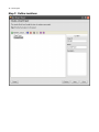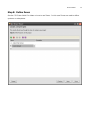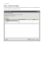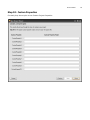
1
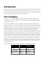
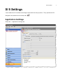
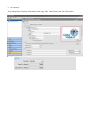
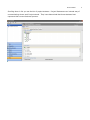
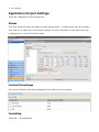
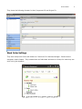
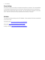
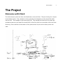
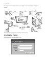
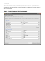
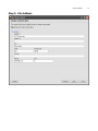
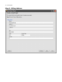
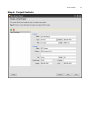
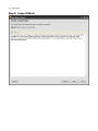
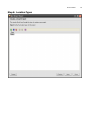
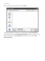
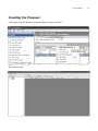
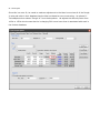
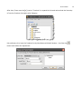
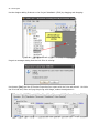
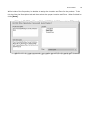
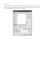
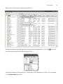
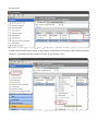
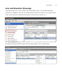
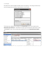
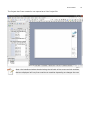
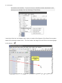
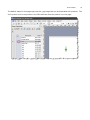
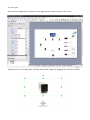
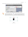
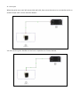
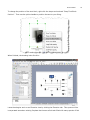
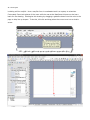
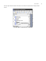
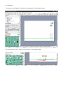
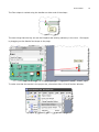
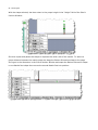
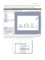
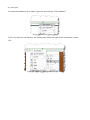
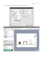
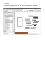
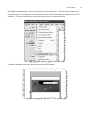
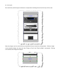
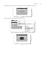
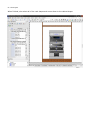
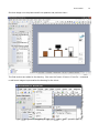
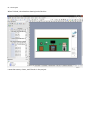
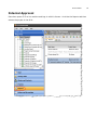
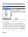
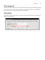
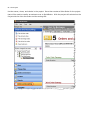
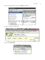
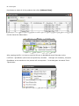
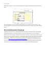
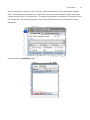
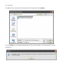
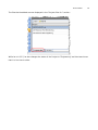
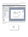
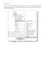
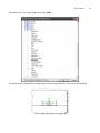
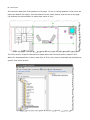
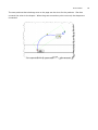
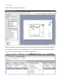
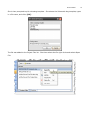
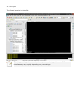
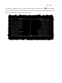
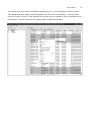
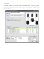
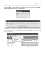
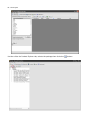
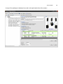
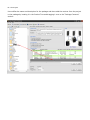
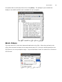
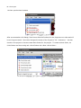
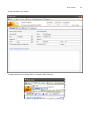
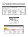
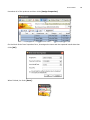
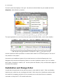
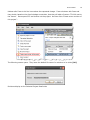
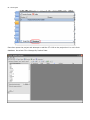
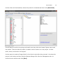
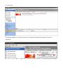
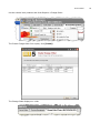
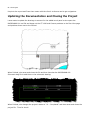
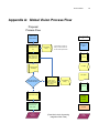
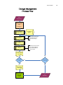
1
1
Table of Contents
Table of Contents ....................................................................................................1
Introduction ............................................................................................................3
The Company ..........................................................................................................3
SI 5 Settings ...........................................................................................................1
Application Settings............................................................................................... 1
Application Project Settings .................................................................................... 4
Phases.............................................................................................................. 4
Contract Percentages .......................................................................................... 4
Formatting ........................................................................................................ 4
Work Order Settings ........................................................................................... 5
Phase Settings ................................................................................................... 6
The Project..............................................................................................................7
Discovery with Client ............................................................................................. 7
Creating the Project............................................................................................... 8
Step 1: Project Name and Staff Assignments........................................................10
Step 2: Site Address .........................................................................................11
Step 3: Billing Address ......................................................................................12
Step 4: Project Contacts....................................................................................13
Step 5: Scope Of Work......................................................................................14
Step 6: Location Types......................................................................................15
Step 7: Define Locations ...................................................................................16
Step 8: Define Zones ........................................................................................17
Step 9: Contract Percentages.............................................................................18
Step 10: Custom Properties ...............................................................................19
Creating the Proposal ...........................................................................................21
Line and Elevation Drawings ..................................................................................29
Internal Approval .................................................................................................53
Client Approval ....................................................................................................55
Accounting ..........................................................................................................55
Plan and Schematic Drawings ................................................................................60
Second Internal Approval ......................................................................................77
Work Orders........................................................................................................85
Installation and Change Order................................................................................90
Updating the Documentation and Closing the Project.................................................96
2
Table of Contents
Appendix A: Global Vision Process Flow ...............................................................97
3
Introduction
Prior to beginning the tutorial we suggest that you read the Pre-Implementation Guide located in
the SI 5 User Manual. This will help you become familiar with many of the concepts covered in the
Tutorial. This Tutorial covers just one of many of possible scenarios. All pricing (MSRP, Unit Cost,
and Unit Price) is fictitious and should not be considered accurate.
The Company
Global Vision, Ltd. is a system integration company operating in the middle residential market.
Their typical project is less than $100,000. They do primarily home automation with an emphasis
on home theater systems.
Mike is the owner and decision maker. Under him are two sales people, Hans and Franz whose
primary responsibility is to meet with potential clients, gather requirements, manage the proposal
process and close deals. Dave is their lead installer and serves as project manager. Calvin and
Hobbes are the installers. Laura is their designer and works primarily in Visio but dabbles with
AutoCAD. Her primary responsibility is to assist the sales team with proposals and then to
engineer and document closed projects. Marge is their bookkeeper and uses QuickBooks Premiere
to manage their financials. They do not stock inventory for most products with the exception of
wire, connectors, back boxes, etc. Any miscellaneous items that they do not show on a proposal
are accounted for with a 3.5% Miscellaneous Parts percentage. This percentage is only applied to
equipment and not to wire and back boxes installed during the rough-in process (they use a 1%
factor for the “Rough-In” phase to account for connectors, wire ties, staples, etc.). They invoice
most clients in a three step process according to the following percentages: 30% initial, and 50%
upon ordering of primary equipment and 20% upon client approval. They collect 7% sale tax on
both goods and services.
Mike and Marge met with the accountant and came up with the following labor rates.
Job
Cost
Selling Price
Installers
$30.00
$75.00
Project Manager
$40.00
$100.00
Engineer
$50.00
$125.00
4
The Company
After analyzing timesheet data, it became clear that Dave was spending 100% and Laura 50% of
their time on project related activities. Since there are two installers, .5 hrs of Dave’s time and .25
hrs of Laura’s time should be included for each install hour. These direct costs need to be included
in the labor estimating process. Dave is responsible for training the client once the system is
installed and Laura handles all of the programming tasks.
Mike, Laura and Dave spent several hours defining their business process. The results of their
work are shown in “Appendix A: Global Vision Process Flow” on page 97.
SI 5 Tutorial
SI 5 Settings
Laura loaded the SI 5 software and Marge helped with the setup process. They opened the SI 5
Navigator and started with the setup tab.
Application Settings
Setup tab -> Application Settings tab
1
2
SI 5 Settings
They setup their Company Information with logo, Misc. Parts Factor and Tax information.
SI 5 Tutorial
Scrolling down in list you see the list of project statuses. Project Statuses are an internal way of
communicating where each Project stands. They have determined that these statuses best
represent their current business process.
3
4
SI 5 Settings
Application Project Settings
Setup tab->Application Project Settings tab
Phases
Then they setup their labor information for each project phase. As noted above, they do not add a
Misc. Parts % for items sold in the Rough-In phase. For more information on Misc Parts % as well
as Equipment %, see the SI 5 User’s Guide.
Contract Percentages
They use the following contract percentages for the majority of their projects:
Formatting
Setup tab -> Formatting tab
SI 5 Tutorial
5
They chose the following formats for their Component ID and Project ID:
Work Order Settings
They have setup both Calvin and Hobbes as “resources” for Business Manager. Resources are
assigned to Work Orders. They created them as Individuals and also as a Group for when they are
sent out to jobs together.
6
SI 5 Settings
Phase Settings
GVL wants to improve their ability to accurately forecast labor on proposals. They use QuickBooks
to track project timesheets and job cost information. Mike and Marge met with the accountant to
determine fully burdened labor rates for the staff. They were particularly interested in direct labor
costs. These are cost that are directly associated with the delivery of a project.
Database
They spent several days setting up their SI 5 database. Some examples of how they accomplished
this are shown here:
Downloading data: http://www.screencast.com/t/D4qYM0hGlo
Editing Data: http://www.screencast.com/t/XQlT17CH8N
Creating a Package: http://www.screencast.com/t/iZ0BHFiC_r
SI 5 Tutorial
7
The Project
Discovery with Client
The initial discovery with the client, the MacGowans, went as follows. They are looking for a simple
home theater option. They entertain on their covered porch frequently so they would like audio
there as well. Their budget is right around $25,000. They bought the house new five years ago
and believe that they can obtain the AutoCAD file of the floor plan from the builder. After the initial
discovery, Franz made the initial sketch of the systems that only he and one other person can
read:
8
The Project
Not being particularly skilled at drawing, Franz asked Laura to make a better sketch of the
systems:
Work now begins on the proposal by starting a Project in SI 5.
Creating the Project
Franz launches SI 5 and is prompted to login:
SI 5 Tutorial
The SI 5 Navigator opens and the Start tab displays. Click the “Create a new project” link.
9
10 The Project
The ten step wizard for creating a new SI 5 Project will open to step one. He proceeds to fill in
information for each of the ten steps. He wisely consults the “Creating an SI 5 Project” section of
the SI 5 User’s Guide.
Step 1: Project Name and Staff Assignments
SI 5 Tutorial
Step 2: Site Address
11
12 The Project
Step 3: Billing Address
SI 5 Tutorial
Step 4: Project Contacts
13
14 The Project
Step 5: Scope Of Work
SI 5 Tutorial
Step 6: Location Types
15
16 The Project
Step 7: Define Locations
SI 5 Tutorial
Step 8: Define Zones
See the “SI 5 User Guide” for ideas on how to use Zones. In this case Zones are used to define
systems or subsystems.
17
18 The Project
Step 9: Contract Percentages
It was decided that since this is a small project, they are going to bill for it as 50% Initial payment
and the remainder upon completions of work.
SI 5 Tutorial
Step 10: Custom Properties
Currently they do not plan to use Custom Project Properties
19
20 The Project
When he finishes entering the information, he clicks [Save].
The default save location for a project in SI 5 is C:\Documents and Settings\username\My
Documents\D-Tools SI5 Projects\Client Name\Project Name for Windows XP users. For Vista
users, the default path is C:\Users\username\Documents\D-Tools SI 5 Projects\ Client
Name\Project Name.
SI 5 Tutorial
Creating the Proposal
Franz right-clicks the project and selects “Open Project in SI Text”:
The project opens:
21
22 The Project
Since this is a retro-fit, he needs to make an adjustment to the labor hours since all of the RoughIn wire and cable in their database has the labor set based on new construction. He selects DToolsÆOptions then selects “Rough-In” from the dropdown. He adjusts the difficulty factor from
100% to 150% which means that he is charging 50% more hours than is associated with each in
the Product database.
SI 5 Tutorial
23
After that, Franz uses the [+] next to “Products” to expand the list and notices that the hierarchy
of how the Products list begins with Category.
His preference it to have the Products list by ManufacturerÆModel Number. He clicks the
button and makes the adjustment:
24 The Project
He then begins adding Products to the Project DataMatrix (PDM) by dragging and dropping:
He gets a message stating that the Unit Price is missing:
He chooses [Yes] and the SI Product Properties form opens with the Price tab selectd. He clicks
the Price tab and, after verifying the pricing with Marge, makes the adjustment:
SI 5 Tutorial
25
While inside of the Properties, he decides to assign the Location and Zone for the product. To do
this he clicks the Description tab and then selects the proper Location and Zone. When finished he
clicks [Save].
26 The Project
He then continues to add Products to the PDM by dragging and dropping until he has all of the
Products that he feels completes the Project. When he dragged wire to the PDM, he was prompted
to select a Head End, wire length, and a terminal start/end:
SI 5 Tutorial
When Franz is finished, the proposal looks like this:
Although he has been saving frequently (that just might be sage advice), he clicks
one more
time then closes the Project by selecting File->Exit:
The project displays in the project grid. The project is still checked out to Franz. This is indicated
in the Checked Out To column.
27
28 The Project
In order to allow other users access to the project, Franz selects the project right-clicks and selects
“Check In” (he could have also used the “Check In this project” link):
SI 5 Tutorial
29
Line and Elevation Drawings
Laura then launches SI 5 on her machine and is prompted to login. She has been assigned a
license of SI 5 Standard. She clicks the Project tab then selects the project in the Projects section
of the screen and clicks “Check Out this project” so that she has “custody” of it.
She selects the project and then right-clicks and selects Open in Visio->New Drawing:
30 The Project
She selects their custom template and adds a name to the drawing. The naming convention they
use for all project files is to add the Project Number to the file name.
The file that was created does not display on the Project Grid tab but can be viewed via the
Selected Project Details tab. She selects the project right-clicks and then selects Open in Visio>MACGOWAN-001.vsd. She could have also opened the file via the Selected Project Details
tab:
SI 5 Tutorial
The Project that Franz created is now opened as a Visio Project file:
Note: the interface windows docked along the left side of the screen and the toolbars
that are displayed will vary from machine to machine depending on changes the user
31
32 The Project
has made to the interface. If you do not see an interface window mentioned in this
tutorial you can display them by Selecting D-ToolsÆView:
Laura then clicks the Line Diagram tab in order to create a flow diagram of the Game Room system
based off the sketches made earlier. The first Product she drags from the PDM to the drawing page
is the plasma:
SI 5 Tutorial
33
The default shape for this page type uses the .jpg image that can be associated with products. The
Visio symbol next to the product in the PDM indicates that the product is on the page:
34 The Project
She continues dragging the Products to the page that she wants to show in this view:
Because this is a Line page type, she can resize these shapes by dragging the selection handles:
SI 5 Tutorial
She then uses the Connector Tool in Visio to make the connections between products:
Tip: The cursor displays like this
when you are using the Connector Tool.
When you move the cursor over a Connection Point on a shape, the point turns red:
35
36 The Project
When the point turns red, left mouse click and hold, then move the cursor to a connection point on
another shape until it turns red then release:
You can use the green handles on the line to reposition the line as desired:
SI 5 Tutorial
To change the position of the text block, right click the shape and uncheck “Snap Text Block
Position”. Then use the yellow handle to position the text to your liking.
When finished, the drawing looks like this:
Laura then begins work on an Elevation view by clicking the Elevation tab. This system will be
incorporated around an existing fireplace that houses a fish tank filled with many species of fish
37
38 The Project
including a killer crayfish. How a crayfish lives in a saltwater tank is a mystery to scientists.
Fortunately Franz took photos of the room while he was at the MacGowan’s house so she has a
basis for the drawing. She begins this drawing by dragging a guideline down from the ruler to the
page to help line up shapes. To do this, left-click and drag when the cursor turns into a double
arrow:
SI 5 Tutorial
She then right-clicks the Cabinet Tools stencil in the Stencil Tree and selects “Display Docked
Stencil”.
39
40 The Project
The shapes in the Cabinet Tools stencil are displayed in the Shapes window:
She then drags the Floor shape from the stencil to the drawing page:
SI 5 Tutorial
41
The Floor shape is resized using the handles on either end of the shape:
The next things that she lays out are the fireplace and existing cabinetry in the room. She begins
by dragging out the Mantle Post shape to the page:
To make sure that the mantle is the proper size, she selects View->Size & Position Window:
42 The Project
With the shape selected, she then enters in the proper height in the “Height” field of the Size &
Position Window:
She then copies and pastes the shape to represent the other side of the mantle. To assure a
proper distance between the mantle posts she drags the Bottom Dimension shape to the page.
She types in the dimension in the Size & Position Window and snaps the Bottom Dimension shape
to one Mantle Post shape then moves the second Mantle Post into position:
SI 5 Tutorial
43
Once positioned correctly, she deletes the Bottom Dimension shape from the page. She continues
to drag shapes form the Cabinet Tools stencil to complete the fireplace and cabinets:
She keeps the cabinet bottom on the right open to show where the rack will go and adds a door to
the cabinet on the left by right-clicking the shape and selecting “Show Solid Door”:
44 The Project
To remove the shadow from a shape, right-click and uncheck “Show Shadow”:
To fill in the color for the cabinets, she selects each shape then right-clicks and selects Format>Fill:
SI 5 Tutorial
She then selects “Wood – Zebrawood” from the “Pattern” dropdown:
45
46 The Project
She then begins work on building the rack. She begins by dragging over the rack and rack
components from the PDM to the drawing page:
SI 5 Tutorial
She begins assembling the rack by first positioning the electronics. Each elevation shape has a
connection point for snapping to the connection points on the rack which are spaced out at 1.75”
intervals. To see the connection points she selects View->Connection Points:
A red box indicates when two connection points are connected:
47
48 The Project
She continues positioning the electronic components including the vent at the top of the rack:
Next she drags over the rack shelves and positions them around the components. When a shape
covers another shape, she uses the Visio “Bring to Front” and “Send to Back” commands. Clicking
once selects the foreground shape:
SI 5 Tutorial
She pauses then clicks in the center of the shape to select the shape behind the shelf:
She then right-clicks and selects Shape->Bring to Front:
49
50 The Project
When finished, she selects all of the rack shapes and moves them to the cabinet shape:
SI 5 Tutorial
She then drags over the plasma and front speakers and positions them:
The final touches are added to the drawing. She uses the Insert->Picture->From file… command
to add some images to personalize the drawing for the client:
51
52 The Project
When finished, the elevation drawing looks like this:
Laura then saves, closes, and Checks in the project.
SI 5 Tutorial
Internal Approval
Dave then opens SI 5 on his machine and logs in with his license. He clicks the Reports tab then
selects the project in the Grid:
53
54 The Project
The reports he generates are the Detail Cost Summary and Gross Profit by Phase reports. To
generate the reports, he selects the Project and then double clicks the report definition from the
Report List. The reports display on separate tabs:
After reviewing, he clicks the [Export To PDF] (
) button and then emails these reports to Mike
for approval. Mike is lounging on the beach in Hawaii but takes time to review these and sends
back his word of approval.
Dave then runs additional reports that will be presented to the client: Proposal, Contract, Cover
Page, and Scope of Work. In addition to these reports, he prints the Line and Elevation pages
created by Laura.
SI 5 Tutorial
55
Client Approval
Franz then meets with the client to present the Proposal and drawings. The MacGowans are beside
themselves and sign off on the Project. While there, he takes even more photos of the MacGowan
home to assist Laura in the design and engineering of the project.
Accounting
Dave opens SI 5 and opens the Project. He selects D-Tools->Project Information and changes the
status to “06 – Approved”:
56 The Project
He then saves, closes, and checks in the project. Dave then creates a Sales Order for the project
that will be used to transfer an estimate over to QuickBooks. With the project still selected on the
Projects tab he clicks the Order and Accounting tab:
SI 5 Tutorial
He clicks the Sales Orders tab and then clicks [New]->SalesOrder:
A new tab is created for the Sales Order:
Dave then clicks [Add Item]:
57
58 The Project
He chooses to select all of the products then clicks [Add and Close]:
He then Saves the Sales Order:
After creating the SO, it is time to push the SO over to QuickBooks as an Estimate via the
LinkTools – QuickBooks (also known as QuickLinks) interface.
Although not necessary, he opens
QuickBooks on his machine so the process will move quicker. In the Navigator he selects Tools>QuickLinks:
SI 5 Tutorial
59
The D-Tools QuickLinks form opens. Since he wants to create in estimate, he selects “Estimate”
from the View dropdown and then clicks [New]:
He then selects the proper Sales Order and clicks [OK]:
The QuickLinks Estimate form opens. He assigns the Customer:Job and adds all of the products
from the Sales Order to the Estimate. All of these products have been sold by them before and are
therefore linked to QuickBooks items. He clicks [Save] to transfer the estimate over to
QuickBooks:
Once the estimate is transferred to QuickBooks, he emails Marge to inform her of the transaction.
Since all of the products were added to the Sales Order, he wants to change the status of the Sales
Order to “Closed”. He clicks the Orders and Accounting tab->Sales Order tab and double-clicks the
60 The Project
Sales Order to open it. He then uses the dropdown to change the status and then saves the Sales
Order:
Since the Estimate is over in QuickBooks, Marge does not even need to interact with SI 5. She
opens QuickBooks on her machine and reviews the Estimate before creating Invoices and Purchase
Orders.
Plan and Schematic Drawings
Meanwhile, Franz has been in communication with the architect, Irene Drawthings, who designed
the MacGowan’s house. She does not want to provide the .dwg file since it is her intellectual
property but would be happy to provide a printed copy of the plans. After explaining that they just
want the two rooms that they working on, the architect agrees to give them a partial floor plan and
an elevation in .dwg format. Franz sent Irene a handy .pdf file (that he downloaded from the DTools forum http://www.d-tools.us/showthread.php?t=1041 ) detailing the commands that must
be run on the file in order to import into Visio. At first she did not want to spend the two minutes
required to run these commands but a phone call from an angry Mrs. MacGowan helped.
SI 5 Tutorial
61
Once he receives the email with the .dwg files, he downloads them to his machine and renames
them. Since these are not actual SI 5 project files, they do not name these files with the project
number as they do for SI 5 project files. To keep all files together he launches SI 5 and then clicks
the Projects tab. He selects the project in the Project Grid and then clicks the Selected Project
Details tab:
He then clicks the [Add File] button:
62 The Project
The Add File form opens and he browses to the file and then clicks [Open]:
He clicks [OK] for the message stating that the files will be copied to the same directory as the
project file:
SI 5 Tutorial
63
The files that he added are now displayed in the “Projects files for:” section:
While he is in SI 5, he also changes the status of the Project to “Engineering” and lets Laura know
that it is her time to shine.
64 The Project
Laura then opens the Visio file for the Project and clicks the Plan View tab. Her first order of
business is to insert the AutoCAD file onto a Plan page type in Visio. Laura is kind of a geek and
actually read the user’s guide for SI 5 and she follows the instructions for this (see Visio Interface
section of the SI 5 User’s guide for details).
SI 5 Tutorial
65
She begins by dragging out some stock Visio shapes to represent the furniture in the house (Laura
uses Visio 2003 Professional so she has access to many stock Visio shapes):
She then drags out one of the front speakers for the surround system. The default Plan shape for
a speaker drops:
66 The Project
For the in-wall and on-wall speakers in projects, she prefers to show a scaled shape instead of the
default Plan speaker shape. To change the shape, she right-clicks the shape and selects D-Tools>Shape->Change Shape:
SI 5 Tutorial
She selects the “Plan Scale” shape and clicks [OK]:
The shape is then changed to a scaled shape that she then positions in the wall of the drawing:
67
68 The Project
She continues adding all of the speakers to the page. For the in-ceiling speakers on the porch she
leaves the default Plan shape. She then adds the touch panel, plasma, and the rack to the page
(all products are selected below to make them easier to see):
The touch panel is a specific Manufacturer shape rather than the stock generic shapes in SI 5.
When GLV downloaded their Crestron data from D-Tools, they chose to download the Manufacturer
specific Visio stencil as well:
SI 5 Tutorial
The next products that she drags over to the page are the wires for the products. She then
connects the wires to the shapes. When the green connection point turns red, the shapes are
connected:
69
70 The Project
When finished, the page looks like this:
When she finishes, she saves and closes the Project. She is going to create a Schematic drawing
for the system but wants to use AutoCAD for this. She selects the Project in the Project Grid and
then right-clicks and selects Open in AutoCAD->New Drawing:
SI 5 Tutorial
71
She is then prompted to pick a drawing template. She selects the Schematic.dwg template, types
in a file name, and clicks [OK]:
The file was added to the Project Files list. She then selects the file right-clicks and selects Open
File:
72 The Project
The Project launches in AutoCAD:
The display settings above are based on my personal settings. Your AutoCAD
interface may vary slightly depending on your settings.
SI 5 Tutorial
She begins by dragging out the all of the products that she wishes to wire.
The Schematic
blocks in SI 5 list the inputs on the left side of the block and the outputs on the right side of the
block. Each I/O has a connection point next to it:
73
74 The Project
She moves and positions the blocks on the sheet until they are in the desired positions:
She then drags out the wire blocks. The wire blocks used on Schematic sheets in SI 5 are red
when not connected to I/Os, and turn green when both ends are connected to I/Os:
SI 5 Tutorial
When you move and end of the wire block to an I/O connection point, an orange box displays:
75
76 The Project
When she is finished making connections, the drawing looks like this:
SI 5 Tutorial
Second Internal Approval
After finishing, Laura then saves, closes, and checks in the project and lets Dave know that it is
ready for review. They decide to do a “working lunch” so Dave logs into SI 5. He then
synchronizes his database:
He checks out the project.
77
78 The Project
Since he wants to be able to work “offline” (not connected to the network), he selects File>Disconnect from SI5.5 Server:
He gets prompted to make sure he’s done everything needed before disconnecting from the server:
He closes SI 5 and then shuts down his laptop. They head over to a familiar coffee joint to discuss.
Laura points out that they have done similar systems to this one many times with a few minor
differences depending on the Project. They decide to create a Package in SI 5 so that they can “resell” this system in the future without having to build it from scratch each time.
SI 5 Tutorial
79
They decide that they want to package the speakers as a 5. 1 surround option for future clients.
They decide that they want to have the speakers and the wire in the package. To do this, Dave
open the Project in the SI 5 Text interface (they could use any interface to do this) and select all of
the products. He then right-clicks and selects Add->Create New Package:
80 The Project
The Package Properties form opens and he adds a name and description. Since this fancy coffee
shop has internet access, he scours the web for a picture of a surround system and adds it to the
package properties:
SI 5 Tutorial
81
Since he is within a project, he makes sure to select the Location and Zone for these products and
then clicks [Save]. He clicks [Yes] when prompted to update the MasterTable and then [Yes]
when prompted to add the package to the MasterTable:
They realize that this package could be the basis for some complete solutions including a receiver
and a display device. Dave Tools->Manage My Product Data in the Navigator. The MMPD interface
opens in its own window:
82 The Project
He then clicks the Product Explorer tab, selects the package then clicks the
button:
SI 5 Tutorial
A copy of the package is displayed on a tab in the right-hand side of the screen:
83
84 The Project
He modifies the name and description for the package and then adds the receiver from the project
to the package by locating it in the Product Tree and dragging it over to the “Package Contents”
section:
SI 5 Tutorial
85
He repeats that for the display device then clicks [Save]. The package he just created now
displays in the MMPD interface and is available for use in projects:
Work Orders
They shut down SI 5, finish their lattes and head back to the office. When they get back to the
office, Dave connects his laptop to the network and opens SI 5. Since he is disconnected from the
SI5.5 Server, he is not prompted to login. To put himself back “online” he selects File->Connect to
SI5.5 Server:
86 The Project
He then synchronizes his data:
After a conversation with Marge, Dave knows that the Products for the Project are on order and will
be arriving next week. Dave then changes the status of the Project to “08 - Production”. He then
checks in the project so he can create Work Orders for the project. To create a Work Order, he
clicks Orders and Accounting tab->Work Orders tab->New->Work Order:
SI 5 Tutorial
The Work Order form opens:
To add products to the Work Order, he selects Add->Item(s):
87
88 The Project
He plans on creating two Work Orders, one for the Rough-In and Trim Phase, and one for the rest
of the work. When the “Add Items to Order” form opens, he uses the filter in the Phase column to
filter to “Rough-In”:
He then clicks [Select All] followed by [Add and Close]:
The Equipment displays on the Work Order form:
SI 5 Tutorial
He selects all of the products and then clicks [Assign Properties]:
On the Work Order Item Properties form, he assigns the team and the expected install date then
clicks [OK]:
When finished, he clicks [Save]:
89
90 The Project
The work order then displays in the grid. He selects the Work Order he just created and clicks
[Reports]->Work Order by Location:
The report generates on a tab. He prints two copies of the Work Order, one for each installer:
He then repeats the above procedure to create a Work Order for the following day for the rest of
the products in the project.
He wants to print additional reports for the install team so he clicks the Reports tab in the
Navigator then launches the Reporting Center to run their installation reports: Pick List, Brother
Wire Labels, Checklist by Location, etc… He also prints the Elevation, Plan, and Schematic pages to
send with the installers.
Installation and Change Order
A week later the equipment arrives and the project is now ready for install. Calvin and Hobbes
load the truck, make the trek, and begin the install. While there, Mrs. MacGowan mentions that
she would like a separate controller for the covered porch so they don’t have to constantly
remember to bring the ST-1700 outside with them.
SI 5 Tutorial
91
Hobbes calls Franz to let him know about the requested change. Franz sits down with Dave and
they decide, based on the client’s budget constraints, that they will add a Crestron CT-1000 next to
the Jacuzzi.
Dave opens SI 5 and checks out the project. He then clicks “Create a new revision of
this project”:
The following screen opens. They leave the default file name for revisions so he clicks [OK]:
Revisions display on the Selected Project Details tab:
92 The Project
Dave then opens the project and attempts to add the CT-1000 to the project but it is not in their
database. He selects File->Manage My Product Data:
SI 5 Tutorial
93
He then clicks the Download tab, selects the product for download and then clicks [Download]:
He calls Marge to confirm the pricing and install hours then clicks the Product Explorer tab to edit
the product. Once he edits the product, he adds it and a Cresnet run to the project. He then
saves, closes, and checks in the project.
He then wants to create a Change Order for the client to sign before they proceed. He selects the
project in the lookup and then clicks the Business Manger tab->Revision Management tab. He
checks the two revisions and clicks [Run]:
94 The Project
The display defaults to “Project Overview” so he selects “Equipment and Labor” from the
dropdown:
SI 5 Tutorial
He then checks both products and clicks Reports->Change Order:
The Create Change Order form opens, click [Create]:
The Change Order displays on a tab:
95
96 The Project
He prints the report and Franz then meets with the client’s to discuss and to get a signature.
Updating the Documentation and Closing the Project
Laura wants to update the drawings to account for the added touch panel so she opens the
MACGOWAN-001.vsd file and drags out the CT-1000 and Cresnet products to the Plan View page
and positions them next to the Jacuzzi:
When finished, she saves and closes the file and then launches the MACGOWAN-001
Schematic.dwg file to add them to the schematic drawing:
When finished, she changes the project’s status to “10 – Completed” and then saves and closes the
project file. Time for lunch!
SI 5 Tutorial
Appendix A: Global Vision Process Flow
Proposal
Process Flow
Legend
Gather Client
Requirements
Create New Project
ProjectName Rev(n)
n=0
ProjectName
Rev(n)
ProjectName could be any
string. It does not have to
be the actual Project Name.
Interaction w/
Client
SI 5
Functions
Add, Remove and
Modify Products to
meet requirements.
SI 5 Data
Create Proposal
with Rev(n)
SI 5 Report
Increment n
Client approved this or
a Previous Revision?
No
Create a new
Revision based on
ANY of the previous
Revisions.
ProjectName
Rev(n)
LinkTools
YES
Create Sales Order
3rd Party
Accounting
Functions
Create QuickBooks
Estimate From
Sales Order
Go To
Engineering
Process
User Note
(Does Not Include Accounting
Integration Work Flow)
Page
Connector
97
98 Appendix A: Process Flow
SI 5 Tutorial
From
Engineering
Project Change
Requires Change
Order
Increment n
Create Revision
ProjectName Rev (n)
ProjectName
Rev(n)
Consider using a field in the
PDM to identify the items
involved in the change.
Add/Remove Items
as needed
Compare Rev(n) with
(n-1)
Not all changes are the result
of the CO. Only select the
changes that will affect the
price of the project.
Select Items for CO
Report
Produce Client
CO Report
YES
CO Accepted
by Client
YES
NO
Continue the
CO Process
NO
Store Client CO
Report PDF
Update Accounting
POs, SOs,
Estimates,
Invoices
To
Engineering
99
100 Appendix B: Help Videos
Appendix B: Help Videos
http://www.d-tools.com/site/downloads/SI%205%20Help%20Videos.pdf