1
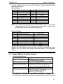
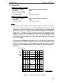
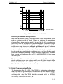
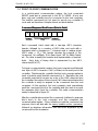
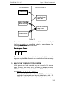
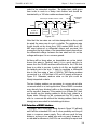
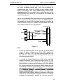
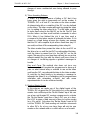
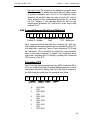
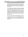
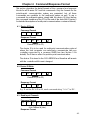
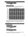
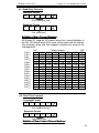
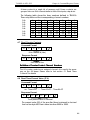
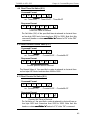
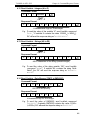
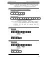
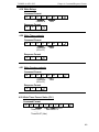
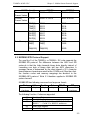
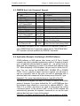
T100MD+ & MX+ PLC
Chapter 3 : Host Communication
Pros and Cons: This method is the easiest to program since
there is no need to handle the token with the token master
or perform extensive error check on the response string.
However, this method uses one input of each PLC and as
many outputs on the master-signal generator PLC as there
are PLC masters. It also requires wiring the PLCs to the
master-signal generator PLC and hence is the most costly
method of all.
3.2.5 Command/Response Block Format (Multi(Multi-point)
@
n
n
x
x
.... .... ....
Device ID Header
x
Data
x
*
FCS Terminator
Each command block starts with the character "@" and twobyte hexadecimal representation of the controller's ID (00 to FF),
and ends with a two-byte "Frame Check Sequence" (FCS) and
the terminator. FCS is provided for detecting communication
errors in the serial bit-stream. If desired, the command block
may omit calculating the FCS simply by putting the characters
"00" in place of the FCS.
Calculation of FCS
The FCS is 8-bit data represented by two ASCII characters (00 to
FF). It is a result of Exclusive OR sequentially performed on each
character in the block, starting from @ in the device number to
the last character in the data. An example is as follow:
@
0
4
Device ID
@
0
4
R
V
I
R
V
I
A
Header Data
4
8
*
FCS
0100 0000
XOR
0011 0000
XOR
0011 0100
XOR
0101 0010
XOR
0101 0110
XOR
0100 1001
3-9