1
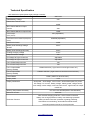
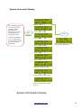
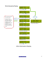
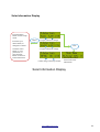
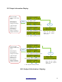
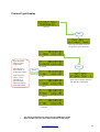
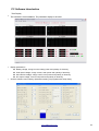
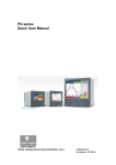
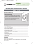
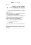
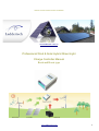
*Please read the manual before installation www.laddertech.com.au Professional Wind & Solar Hybrid Street Light Charge Controller Manual Buck and Boost type www.laddertech.com.au 1 Notes : Thank you for purchasing our controller, please read the user manual carefully before installation and use the product with due care. The installation must be done by an experienced technician and be in accordance with the user manual to ensure that the product can work correctly. The Controller should not be exposed to long-term corrosive gas or a moist environment. Do not put this product in wet, rain exposed, dusty, shock, or corrosive environments. Do not expose this product to strong electromagnetic interference. Do not open the controller or try to repair. Contents Charge Controller Manual.............................................................................................................1 Technical Specification..................................................................................................................3 Universal Functions.......................................................................................................................4 System Schematic.........................................................................................................................6 Power On Display..........................................................................................................................7 Parameters Browsing Display.......................................................................................................8 Main Menu Display........................................................................................................................9 System Information Display.........................................................................................................10 Wind Information Display.............................................................................................................11 Solar Information Display............................................................................................................12 DC Output Information Display....................................................................................................13 Product Type Display...................................................................................................................14 PC Software Introduction............................................................................................................15 Warranty And After-Sales Service...............................................................................................16 Appendix......................................................................................................................................17 www.laddertech.com.au 2 Technical Specification 24V Wind Solar Hybrid (Street Light) Charge Controller Item No. 800W 24V Rated Battery Voltage 24V Rated Wind Turbine Power 500W Wind Turbine Maximum Input Current 30A Wind Turbine Maximum Input Power Unload Voltage 750W 50V (Adjustable) (factory default) Unload Wind Turbine Rotation Speed (factory 400RPM (Adjustable) default) Rated Solar Power 300W Battery Over-discharge Voltage 20.4V Shutoff Battery Over-discharge Recovery 23.0V Floating Charging Voltage 27.0V Output Protection Voltage 35V PV Voltage Of Light-Control On Adjustable PV Voltage Of Light-Control Off Adjustable Line 1 Rated Output Current 10A Line 2 Rated Output Current 10A Line 1 Output Mode 1 Modes selection ( Light-control on and Light-control off ) (Factory Default) Line 2 Output Mode 2 Modes selection ( Light-control on and time-control 5 hours ) (Factory Default) Control Mode PWM,(MPPT for buck function) Display Mode LCD Display Parameters wind power , wind voltage , wind current , wind turbine speed ,PV power , PV voltage , PV current , battery voltage , battery power ,charge current, over voltage ,under voltage ,over load, short circuit , night mode, DC output modes etc Working Temperature &Humidity -20~+55°C/35~85%RH(Without Condensation) Quiescent Current 20±2 mA solar reverse-charging protection , solar reverse-connection battery over charge protection, battery over-discharge protection Protection Function battery reverse-connection protection, lightning protecting, wind turbine current limiting, wind turbine automatic brake, over load protection and short circuit protection www.laddertech.com.au 3 Universal Functions Multiple protective features for the wind turbine; open circuit with dump load control, over rotation speed protection, over voltage limiting, over current limiting. When the total current input from the wind and solar is higher than the limit current set point or the battery is full, the PWM duty cycle of the controller will be decreased until the battery is fully charged. The controller then disconnects the charging loop and the wind turbine will be on no-load operation. In order to prevent the wind turbine over rotating, this controller is designed with over-current and over-voltage limitation via an inbuilt dump load controller. The controller will automatically start the PWM voltage intelligent dump load protection. Maximum charging current limitation for battery User can set the battery capacity and maximum charge current according to systems exact configuration. To ensure the service life of battery. Wind turbine and solar panel is intelligent complementary and independent charging The Wind turbine and solar panel use intelligent complementary and independent charging. The solar panel circuit has open circuit protection, and wind turbine has open circuit, over voltage, over rotation speed and over current protection. This optimises service life for system components . The controller has two DC outputs specially designed for street light system. Each DC output has 9 modes of controlling output, including : 1. Light-control on and light-control off ( L- On and L-Off) 2. Light-control on and time-control off (L-On and T-Off) 3. Time-control on and time-control off (T-Off and T-On) 4. Constant on 5. Half –power light-control on and light-off (H-L-On and L-Off) 6. Half-power light-control on and time-control off ( H-L-On and T-Off) 7. Half-power time-control on and time-control off (H-T-ON and T-Off) 8. Half-power constant on (H-Constant On) 9. Constant off Manual brake Use the manual brake to stop the wind turbine and to avoid bad weather damaging the hybrid system. Switch on the manual brake during strong winds, typhoon or hurricane Wind turbine charging control switch. The wind turbine charging can be manually turned on or turned off. Wind charging is shut off if the switch is in the off position. The wind charging is normal if the switch is in the on position. To avoid sparks when connecting the wind turbine with controller, switch off the wind turbine charging switch. Solar charging control switch. The solar charging can be manually turned on or off. The solar charging is shut off if the switch is in the off position. The solar charging is normal if when the charging switch is in the on position. To avoid www.laddertech.com.au 4 sparks when connect the solar panel to controller, switch off the solar charging switch. Output control switch. Turn on or turn off the output switch, The DC output will be shut off when the output switch is in the off position. The DC output is normal if the switch is in the on position. To avoid sparks when connecting the loads to controller, switch the output to the off position. Multilevel menu display by LCD, intelligent button sound With LCD display, support multilevel menu . More parameters can be shown with intelligent button sound. It is more humanized design. Boost & Buck Functions Wind turbine output voltage intelligent boost The boost module starts automatically when the wind turbine voltage is lower than battery voltage, this ensures that the wind turbine normally charges the battery. The boost module shuts off automatically when the wind turbine voltage is higher than battery voltage. Wind turbine output voltage intelligent buck The buck module starts automatically when the wind turbine voltage is higher than battery voltage, The controller tracks in real-time the maximum power of wind turbine and real-time limits the of winding current of wind turbine . This solves the problem of over-heating the wind turbine. Wind Max Current Tracking (MCT) and Max Power Point Tracking (MPPT) With the Max Current Tracking and Max Power Point Tracking and with boost module, the wind turbine will generate maximum output power and improve the utilization rate of the wind turbine. Impedance matching self-adaption Due to internal resistance of wind turbine, battery, and load, this controller incorporates impedance matching. The wind Turbine will have maximum power utilization rate and maximum power output when the input impedance equals to output impedance, with impedance matching self-adaption. Impedance matching enhances energy efficiency. RS 232 Communication RS232 /RS485 real time communication With serial port communication, data can be analysed from the software installed on a connected computer. Support for the serial port update process With serial port update progress. To modify customization functions . PC and controller set for two-way communication www.laddertech.com.au 5 System Schematic Solar Panel Wind Turbine PC LED Lamp Battery System Schematic. Installation Steps After the wind/solar hybrid system is installed, please connect the controller accurately by following these instructions. • Open the package to check whether the equipment is damaged during transportation or not. • Please turn off the wind charge switch solar charge switch and DC output switch to avoid sparks when the Controller is powered on, (how to turn off the switch, please refer to the menu introduction). • Connect the DC load to “DC OUTPUT” terminals. One load should be connected to "+" and "-” of the “DC OUTPUT Terminals and another load should be connected to "+" and "-2" of the “DCUTPUT” terminals. The mode of load output can be set according to the requirements of the load from the software or LCD press .The half-power is just suitable for LED light. • Connect the battery’s positive pole to the position (+) of “BATTERY” terminal, and connect battery’s negative pole to the negative(-) of “BATTERY” terminal with copper core cable. Although the controller has the battery reversed protection, battery reversed connection is still forbidden. • Connect the output lines of the wind turbine to the “WIND” terminals of the controller. • Connect the solar panels to the “SOLAR” terminals of the controller. www.laddertech.com.au 6 Power On Display Power on Displaying the product range System Initialisation Displaying the item no. www.laddertech.com.au 7 Parameters Browsing Display Press the ESC button to return to the first interface of parameters browsing In the parameters interface, press the menu button to enter the main menu. 1. The battery power, state; voltage and charging current Menu 2. Night and day state, solar voltage and charging current ESC 3. Wind turbine rotation speed, voltage and charging current 4. Wind turbine output power and current. Press the up or down button, browse the parameters 5. DC output 1 mode, light-control-on-volt, time-control-off -time 6. DC output 2 mode, light-control-on-volt, time-control-off -time 7. DC output power, current 8. Total input power, solar input power, wind input power 9. Total energy system generated www.laddertech.com.au 8 Main Menu Display Main Menu Display Menu 1. Press the menu button, check system information Menu ESC 2. Press the menu button ,check the wind information Menu Press the Esc button return 3. Press the menu button ,check the solar to the first interface of the information parameters browsing Menu Press the up or down button, browse the above 7 interfaces 4. Press the menu button, check the DC output 1 information Menu 5. Press the menu button, check the DC output 2 information Menu Menu 6. Display the item no. 7. Display the time . www.laddertech.com.au 9 System Information Display Press the Menu button to enter setup mode. When the setting parameters are flashing, press the up or down button, to change the content. Click the menu button if to save parameters, or press the ESC button to return to system information. 1.Battery capacity Menu 2. Clean up the energy ESC 3. Low voltage 4. Low voltage recovery Press the Esc button to return to the system information. 5. Over voltage 6. Over voltage recovery 7. Floating charging voltage 8.Over-load protection voltage 9.Over-load protection voltage recovery System Information Display www.laddertech.com.au 10 Wind Information Display 1. To choose MPPT On 2. Wind max rotation speed limit Press the Menu button, enter setup mode. When the setting parameters, press the up or down button, to change the content. Click the menu button if need to save parameters, or press the ESC to return to the Wind Information Menu. ESC Menu 3. Wind turbine magnetic pole number 4.Manual brake Press the Esc button return to the wind information 5. Wind charge switch by manual 6.Wind max voltage limit 7.Wind max current limit 8.Manual brake time 9.Cut-In voltage Wind Information Display www.laddertech.com.au 11 Solar Information Display Press the Menu button to enter setup mode. Press the up or down button, to change the content. Click the menu button to save parameters, or press the ESC button to return to Solar information. Menu 1. Light-control on voltage ESC 2. Light-control off voltage 3.Solar charge switch by manual Press the Esc button return to the solar information Solar Information Display www.laddertech.com.au 12 DC Output Information Display Press the Menu button to enter setup mode. Press the up or down button, to change the content. Menu 1. DC ouput1 mode ESC 2. DC output time-control on time Click the menu button to save parameters, or press the ESC button to return to Output information. 3. DC ouput1 time-control off time Press the Esc button return to the output1 information 4. DC output switch by manual Press the Menu button to enter setup mode. Press the up or down button, to change the content. Click the menu button to save parameters, or press the ESC button to return to Output information. 1. DC ouput2 mode Menu 2. DC output2 time-control on time ESC 3. DC output 2 time-control off time 4. DC output2 switch by manual Press the Esc button return to the output2 information DC Output Information Display www.laddertech.com.au 13 Product Type Display Item No. ESC Press the Esc button return to the product type information 1. Year Press the Menu button to enter setup mode. Press the up or down button, to change the content. Click the menu button to save parameters, or press the ESC button to return to Date information. ESC 2. Month Menu 3. Day Press the Esc button return to the date time information 4. Hour 5. Minute 6. Second The above parameters are shown for the 800W-24V model. Other models have the same menu interface as the above. www.laddertech.com.au 14 PC Software Introduction Time Display This software is free installation, The parameter display is as below Display parameters: Battery voltage, charge current, battery power and quantity of electricity Solar panel voltage, charge current, solar power and quantity of electricity Wind turbine voltage, charge current, wind power and quantity of electricity DC output voltage, current, load power and quantity of electricity Click the software menu setting->parameters setting, Popup parameter setup dialog www.laddertech.com.au 15 Warranty And After-Sales Service A one year warranty is provided from delivery date. If the product exceeds the warranty period or is damaged by transportation, improper use, human elements, force majeure, it is no longer under warranty. www.laddertech.com.au 16 Appendix www.laddertech.com.au 17 Ladder Technologies Pty Ltd 294 Palmyra Ave. Shanes Park New South Wales Australia 02 80056908 [email protected] www.laddertech.com.au 18