1
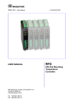
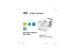
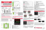
1600
High - Low limiter
r USER'S MANUAL
Issue date
October 2000
1600-0-A0.p65
0037 - 75331
1
11/7/00, 6:14 PM
APPROVALS This instrument is U.L. and c.U.L. approved as controller.
CONTENTS
MOUNTING REQUIREMENTS ........................... 1
DIMENSIONS AND REAR TERMINALS ............ 2
PANEL CUT OUT ............................................... 3
WIRING GUIDELINES ........................................ 3
PRELIMINARY HARDWARE SETTINGS ........... 8
CONFIGURATION PROCEDURE ...................... 9
OPERATING MODE ......................................... 15
Normal display mode ................................. 15
Indicators ................................................... 16
Key functions in normal display mode ........ 16
Operative parameter display mode ............ 16
Key functions in
operative parameter display mode ............. 17
Operating parameters ................................ 17
Limiter function ........................................... 18
Alarm functions .......................................... 19
Serial link ................................................... 19
ERROR MESSAGES ........................................ 20
GENERAL SPECIFICATIONS .......................... 21
MAINTENANCE ................................................ 24
DEFAULT PARAMETERS ............................... A.1
APPENDIX B ................................................... B.1
1600-0-A0.p65
2
11/7/00, 6:14 PM
Model identification
Model
1600
1/16 DIN High - low limiter
Code
1
Output 1
Relay, 3 Amps at 250 Vac (Resistive)
Code
Output 2
0
None
1
Relay, 2 Amp at 250 Vac (Resistive load)
Code
0
None
1
RS 485 + 1 logic input
Code
3
5
Instrument Power
100 - 240 Vac
24 Vac/dc
Code
1600
1
1600-0-A0.p65
0
0
3
3
0
Add to complete model number
0
Typical Model Number
11/7/00, 6:14 PM
The instrument is shipped with a rubber panel
gasket (50 to 60 Sh). To insure the IP65 and
NEMA 4 protection, insert the panel gasket
between the instrument and the panel as shown
below.
MOUNTING REQUIREMENTS
Select a mounting location with the following
characteristics:
1) Minimal vibration.
2) An ambient temperature range between 0 and
50°C (32 and 122 °F).
3) Easy access to the rear of the instrument.
4) No corrosive gases (sulfuric gas, ammonia,
etc.).
5) No water or other fluid (i.e. condensation).
6) Relative humidity of 20% to 80% non
condensing.
Install the instrument as follows:
1) Insert the instrument in the gasket.
2) Insert the instrument in the panel cutout.
3) Pushing the instrument against the panel,
insert the mounting bracket.
4) Torque the mounting bracket screws between
0.3 and 0.4 Nm (2.66 and 3.54 lbf-in).
5) To insure NEMA 4X/IP65 protection, make
sure the instrument does not move within the
cutout .
The instrument can be mounted on a panel up to
15 mm (0.591 in) thick with a square cutout of
45 x 45 mm (1.772 x 1.772 in). For outline refer
to Dimensions and Panel Cutout.
Panel surface texture must be better than 6.3 µm.
bracket
Screw
Panel
Chromalox
Fig. 1
Gasket
1
1600-1-A0.p65
1
11/7/00, 6:14 PM
DIMENSIONS AND REAR TERMINAL BLOCKS
Chromalox
Without RS-485
With RS-485
Fig.2
2
1600-1-A0.p65
2
11/7/00, 6:14 PM
PANEL CUTOUT
WIRING GUIDELINES
A) Measuring Inputs
NOTE: Any external components (like Zener diodes, etc.) connected between sensor and input
terminals may cause errors in measurement due to
excessive and/or not balanced line resistance or
possible leakage currents.
TC Input
+ 10
_ 9
Shield
+ 10
Fig.3
_ 9
Shield
Fig. 4 THERMOCOUPLE INPUT WIRING
NOTE:
1) Do not run input wires with power cables.
2) For TC wiring use proper compensating cable,
preferably shielded (see Appendix B).
3) Shielded cable should be grounded at one end
only.
3
1600-1-A0.p65
3
11/7/00, 6:14 PM
LINEAR INPUT
RTD INPUT
RTD
RTD
10
+
_
9
mA,
mV
or
V
Shield
8
9
10
8
9
+
10
10
_
9
Fig. 5 RTD INPUT WIRING
mA
mV
or
V
G
NOTE:
1) Don’t run input wires together with power
cables.
2) Pay attention to the line resistance; a high line
resistance may cause measurement errors.
3) When shielded cable is used, it should be
grounded at one side only to avoid ground loop
currents.
4) The resistance of the 3 wires must be the
same.
Fig. 6 mA, mV AND V INPUTS WIRING
NOTE:
1) Don’t run input wires together with power
cables.
2) Pay attention to the line resistance; a high line
resistance may cause measurement errors.
3) When shielded cable is used, it should be
grounded at one side only to avoid ground loop
currents.
4) The input impedance is equal to:
Less than 5 W for 20 mAdc input
Greater than 1 MW for 60 mVdc input
Greater than 400 KW for 5 Vdc and 10 Vdc
input
4
1600-1-A0.p65
4
11/7/00, 6:14 PM
B) Logic Input (for models with RS-485 only)
C.1) Relay Outputs
This input is used for remote acknowledgement
(reset).
Safety note:
- Do not run logic input wiring with AC power
cables.
- Use an external dry contact capable of
switching 0.5 mA, 5 Vdc.
- The instrument needs 100 ms to recognize a
contact status variation.
- The logic inputs are NOT isolated from the
measuring input.
OUT 1
1
Class 1
2
NO - OUT 1
C - OUT 1
NC - OUT 1
3
OUT 2
Class 1
(Alarm)
C
6
NO
7
Logic input
14
Fig. 8
The OUT 1 contact rating is 3A/250V AC on
resistive load.
The OUT 2 contact rating is 2A/250V AC on
resistive load.
The number of operations is 1 x 10⁵ at specified
rating.
NOTES 1) To avoid electric shock, connect power
line at the end of the wiring procedure.
2) For power connections use No 16 AWG
or larger wires rated for at last 75 °C.
3) Use cupper conductors only.
4) Don’t run input wires with power cables.
All relay contacts are protected by varistor against
inductive load with inductive component up to 0.5 A.
15
Fig.7
The following recommendations avoid serious
problems which may occur, when relay outputs
are used with inductive loads.
5
1600-1-A0.p65
5
11/7/00, 6:14 PM
C.2) Inductive Loads
High voltage transients may occur switching
inductive loads.
Through the internal contacts these transients
may introduce disturbances which can affect the
performance of the instrument.
For all the outputs, the internal protection
(varistor) assures a correct protection up to 0.5 A
of inductive component.
D) Serial Interface
For units built with optional RS-485 communication
interface.
RS-485 interface allows to connect up to 30
devices with one remote master unit.
I
N
S
T
R
U
M
E
N
T
The same problem may occurs when a switch is
used in series with the internal contacts as shown
in Fig. 9.
C
R
POWER
LINE
LOAD
In this case it is recommended to install an
additional RC network across the external contact
as show in Fig. 9
The value of capacitor (C) and resistor (R) are
shown in the following table.
C
(mF)
R
(W)
P.
(W)
OPERATING
VOLTAGE
<40 mA 0.047 100
<150 mA 0.1
22
<0.5 A
0.33 47
1/2
2
2
260 V AC
260 V AC
260 V AC
12
13
A/A'
A'/A
B/B'
B'/B
COMMON
The cable involved in relay output wiring must be
as far away as possible from input or communication cables.
6
1600-1-A0.p65
6
M
A
S
T
E
R
Fig. 10 - RS-485 WIRING
The cable length must not exceed 1.5 km at 9600
BAUD.
NOTES:
1) This RS 485 serial interface is insulated.
2) The following report describes the signal sense
of the voltage appearing across the
interconnection cable as defined by EIA for
RS-485.
a) The ” A ” terminal of the generator shall be
negative with respect to the ” B ” terminal for
a binary 1 (MARK or OFF) state.
b) The ” A ” terminal of the generator shall be
positive with respect to the ” B ” terminal
for a binary 0 (SPACE or ON).
Fig. 9 EXTERNAL SWITCH IN SERIES WITH
THE INTERNAL CONTACT
LOAD
(mA)
11
11/7/00, 6:14 PM
I
N
S
T
R
U
M
E
N
T
I
N
S
T
R
U
M
E
N
T
E) Power Line and grounding
11
12
A'/A
A/A'
B'/B
B/B'
COMMON
13
4
M
A
S
T
E
R
5
N, L2
POWER SUPPLY
100 to 240 Vac
24 Vac/Vdc
N, L2
R (S,T), L1
Fig.12
R (S,T), L1
NOTES:
1) Before connecting the power line, check that
the voltage is correct (see Model Number).
2) For supply connections use 16 AWG or larger
wires rated for at least 75 °C.
3) Use copper conductors only.
4) Do not run input wires with power cables.
5) Polarity does not matter for 24 Vdc wiring.
6) The power supply input is NOT fuse protected.
Please provide it externally.
Power supply
Type Current
Voltage
24 V AC/DC
T
500 mA
250 V
100/240 V AC
T
125 mA
250 V
When fuse is damaged, it is advisable to verify
the power supply circuit, so that it is necessary to
send back the instrument to your supplier.
7) Safety requirements for permanently
connected equipment:
- Include a switch or circuit-breaker in the
installation.
- Place the switch in close proximity to the
equipment and within easy reach of the
operator.
- Mark the switch as the disconnecting
device for the equipment.
NOTE: A single switch or circuit-breaker can
drive more than one instrument.
8) When the NEUTRAL line is present, connect it
to terminal 4.
9) To avoid shock and possible instrument
damage, connect power last.
11
12
13
Fig.11
7
1600-1-A0.p65
7
11/7/00, 6:14 PM
PRELIMINARY HARDWARE
SETTINGS
1600 without RS-485
1) Remove the instrument from its case.
2) Set J106 according to the desired input type as
shown in the following figure.
V101
INPUT
TYPE
J106
1-2
3-4
5-6
7-8
TC-RTD close
open
open
open
60 mV
close
open
open
open
5V
open
close
open
open
10 V
open
open
close
open
20 mA
open
open
open
close
Fig.13.B
1600 with RS-485
2
4
6
8
1
3
5
7
J106
Fig.13.A
V101
8
1600-1-A0.p65
8
2
4
6
8
1
3
5
7
J106
11/7/00, 6:14 PM
The following is a complete list of parameters. The
lower display will show the parameter code (L1 to
d1) and the upper display will show the selection
code or numerical value. No timeout is applied in the
configuration mode.
CONFIGURATION PROCEDURE
CONFIGURATION KEY FUNCTIONS
RESET In Configuration Mode, it is used only to
scroll back parameters without to memorize a new parameter value.
Used in Configuration Mode to decrease
the parameter value.
Used in Configuration Mode to increase
the parameter value.
FUNC Used to memorize the new parameter
value and go to the next parameter.
+
Loads the default parameters.
+ FUNC or + FUNC
Increases/decreases values at a higher
rate when modifying parameters.
+ RESET or + RESET
Jumps to the Maximum or Minimum parameter value when modifying parameters.
L1 = Serial Interface Protocol
(Skipped if option is not available.)
OFF = No serial interface
nbUS= Modbus
jbUS = Jbus
L2 = Serial Link Device Address
(Skipped if option is not available or L1 = OFF)
From 1 to 255
NOTE: EIA standard allows no more than 31 device
connected by one RS-485.
L3 = Baud Rate for Serial Link
(Skipped if option is not available or L1 = OFF)
Set value from 600 to 19200 baud.
(19200 baud is shown on display as 1920)
CONFIGURATION PROCEDURE
1) Remove the instrument from its case.
2) Open switch V101 (See illustrations under
“Preliminary Hardware Settings.”)
3) Re-insert the instrument in its case.
4) Switch on power to the instrument.
The upper display will show COnF.
NOTE : If "CAL" indication is displayed,
press immediately the s pushbutton and
return to the configuration procedure.
5) Press the “ ” key and the lower display will
show the firmware version.
L4 = Byte Format for Serial Link
(Skipped if option is not available or L1 = OFF)
8E = 8 bits + even parity
8O = 8 bits + odd parity
8
= 8 bits without parity
Press the "FUNC" key to start the configuration
procedure with the first parameter (L1).
9
1600-1-A0.p65
9
11/7/00, 6:14 PM
r1 =Input Type and Range Value
0 = TC J
From
-100 to
1 = TC K
From
-100 to
2 = TC T
From
-200 to
3 = TC E
From
-100 to
4 = TC N
From
-100 to
5 = TC S
From
-50 to
6 = TC R
From
-50 to
7 = TC B
From
0 to
8 = TC L
From
-100 to
9 = TC U
From
-200 to
10 = TC G
From
0 to
11 = TC D
From
0 to
12 = TC C
From
0 to
13 = TC Plat. II From
-100 to
14 = RTD Pt 100 From
-200 to
15 = Linear
From
0 to
16 = Linear
From
12 to
17 = Linear
From
0 to
18 = Linear
From
4 to
19 = Linear
From
0 to
20 = Linear
From
1 to
21 = Linear
From
0 to
22 = Linear
From
2 to
23 = TC J
From
-150 to
24 = TC K
From
-150 to
25 = TC T
From
-330 to
26 = TC E
From
-150 to
27 = TC N
From
-150 to
28 = TC S
From
-60 to
29 = TC R
From
-60 to
30 = TC B
From
32 to
31 = TC L
From
-150 to
32 = TC U
From
-330 to
33 = TC G
From
0 to
34 = TC D
From
0 to
35 = TC C
From
0 to
36 = TC Plat. II From
-150 to
37 = RTD Pt100 From
-330 to
1000
1370
400
800
1400
1760
1760
1820
900
600
2300
2300
2300
1400
850
60
60
20
20
5
5
10
10
1830
2500
750
1470
2550
3200
3200
3300
1650
1110
4170
4170
4170
2550
1560
r2 = Decimal Point Position
(Available only for linear range r1 = 15 to 22)
_ _ _ _ . = No decimal
_ _ _ . _ = One decimal figure
_ _ . _ _ = Two decimal figures
_ . _ _ _ = Three decimal figures
°C
°C
°C
°C
°C
°C
°C
°C
°C
°C
°C
°C
°C
°C
°C
mV
mV
mA
mA
V
V
V
V
°F
°F
°F
°F
°F
°F
°F
°F
°F
°F
°F
°F
°F
°F
°F
r3 = Initial value of the readout scale
(Available only for linear range r1 = 15 to 22)
Range: From -1999 to 9999
r4 = final value of the readout scale
(Available only for linear range r1 = 15 to 22)
Range: From -1999 to 9999
r5 = Offset Adjustment
Range: From -500 to 500
Offset value algebraically added to the measured
value.
r6 = Time constant of the filter applied to the
displayed value
Range: From 0 (filter OFF) to 8 seconds.
(First order filter with selected time constant.)
r7 = Alarm action on input fault.
When the instrument detects an input failure
condition, the alarm will operate as in presence
of:
uP = as in presence of the full scale value.
doun = as in presence of the initial scale value.
10
1600-1-A0.p65
10
11/7/00, 6:14 PM
C1 = Type of limit action
Hi. = High limit (for heating process)
Lo. = Low limit (for cooling process)
Hi.Lo = High and low limit (for special process)
The Out 1 remains OFF until the condition which
generated the shutdown, no longer exists and the
acknowledge action has been performed.
The upper display flashes during a shutdown and
returns to a steady display when the shutdown
condition no longer exists.
When C2 = 0 and OUT 1 is OFF, the RESET LED
is ON.
When C2 = 1 one of the following condition may
occur:
- if no acknowledgement has been made, OUT 1
is OFF and the RESET LED is flashing;
- if the acknowledgement has been made but the
condition which generated the shutdown status
still exists, OUT 1 is OFF and the RESET LED
is steady ON.
C2 = Rearming Mode
O = Acknowledgements rearm (reset) the limiter
(and restart the process) only if the condition
which generated the shutdown status no longer
exists (points A and C of the Example 1). It do
not generate any effect if the condition which
generated the shutdown status still exists (point
B of the Example 1).
I = Acknowledgements enable the automatic
rearmament (reset) of the limiter if the
condition which generated the shutdown
status still exists (point B of the Example 2).
(The instrument rearms (reset) automatically
when the condition which generated the
shutdown status no longer exists).
The shutdown condition can be stored in
permanent memory (see C4).
Acknowledgment can be performed by pressing
the RESET key, by momentarily closing the
external dry contact or by a command from the
serial link.
Notes about limiter function
The relay of the output 1 operates in fail-safe
mode (relay de-energized during shutdown
condition) and latching mode.
The length of the shutdown condition and max/
min measured values are stored in memory and
available for viewing until the next shutdown
condition occurs.
These informations are lost at power down.
During a shutdown condition the max/min
measured values are continuously updated and
can be monitored.
The OUT 1 turns OFF when:
- C1 = Hi and the measured value is greater
than limiter threshold [“Su” parameter (see
Operative parameters”)] or
- C1 = LO and the measured value is less than
limiter threshold [“Su” parameter (see
Operative parameters”)] or
- C1 = HiLO and the measured value is greater
than “Su” parameter (see Operative parameters”) or less than “S1” parameter (see
Operative parameters”).
11
1600-1-A0.p65
11
11/7/00, 6:14 PM
Example 1 - C1 = Hi and C2 = O
HS
C4
0
Su
(Limiter
threshold)
(Limiter
Hysteresis)
1
ON
Relay OUT 1
OFF
C5 = Time Constant of the Filter applied to the
Measured Value for Limit Action.
Range: From 0 (filter OFF) to 8 seconds
Note: First order filter with selected time
Constant.
ON
“Reset” LED
OFF
Flash
Upper display
Steady
FLASH
FLASH
A, B, C = Acknowledgment actions.
NOTE: Acknowledgment B has no effect.
P1 = Alarm Function
(Skipped when the option is not available)
nonE = Not provided
AL.P = Process alarm
AL.b = Band alarm
AL.d = Deviation alarm
When C1 = Hi.Lo, “AL.b” and “AL.d” are not
available.
Example 2 - C1 = Hi and C2 = 1
Su
(Limiter
threshold)
HS
(Limiter
Hysteresis)
ON
Relay OUT 1
OFF
ON
“Reset” LED
OFF
FLASH
FLASH
Flash
Upper display
Steady
FLASH
FLASH
= Shutdown memory
= The shutdown condition will be saved (at
next power up it will be reactivated)
= The shutdown condition will be lost in
case of power down
P2 = Alarm configuration
(Skipped if option is not available or P1 = none)
H.A. = High alarm with automatic reset
L.A. = Low alarm with automatic reset
H.A.Ac = High alarm with automatic reset and
"Silence" function.
L.A.Ac =Low alarm with automatic reset and
"Silence" function.
H.L. = High alarm with manual reset
L.L. = Low alarm with manual reset
A, B = Acknowledgment actions.
C3 = Rearm at Power-up
Auto = Automatic rearm
nAn = Manual rearm
12
1600-1-A0.p65
12
11/7/00, 6:14 PM
NOTE:
1) For band alarm, H.A./H.A.Ac/H.L. signifies
outside band alarm, while L.A./ L.A.Ac/L.L.
signifies inside band alarm.
2) The "Silence" function allows the manual reset
of the alarm even if the alarm condition is still
in progress.
Example for P2 = H.L.
Alarm status*
Relay
Non alarm status
Example for P2 = H.A.
ON
ALM LED
OFF
(Alarm
threshold)
(Alarm
Hysteresis)
FLASH
FLASH
Manual
reset
Alarm status*
Relay
Non alarm status
ON
ALM LED
OFF
(Alarm
threshold)
(Alarm
Hysteresis)
FLASH
Manual
reset
* Alarm Status:Relay energized (P3 = dir)
Relay de-energized (P3 =rEV)
FLASH
Manual
reset
* Alarm Status:Relay energized (P3 = dir)
Relay de-energized (P3 =rEV)
P3 = Alarm Action
(Skipped if option not is available or P1 = none)
dir = Direct action
(Relay energized in alarm condition)
rEV = Reverse action
(Relay energized in non-alarm condition)
Example for P2 = H.A.A.c
(Alarm
threshold)
(Alarm
Hysteresis)
Alarm status*
Relay
Non alarm status
ON
ALM LED
OFF
FLASH
FLASH
Manual
reset
* Alarm Status:Relay energized (P3 = dir)
Relay de-energized (P3 =rEV)
13
1600-1-A0.p65
13
11/7/00, 6:14 PM
P4 =
Alarm Standby (mask) Function
(Skipped if option is not available or P1= none)
OFF =
Standby function disabled
On =
Standby function enabled
d1 = Digital Input (contact closure)
(This is a read only parameter)
Enb =
Digital input enabled
dlS =
Digital input disabled
(The digital input is used as a remote
Acknowledgment .)
If the alarm is programmed as band or deviation,
this function masks the alarm condition at start up
and after a “Su” (limit threshold) changement until
the process variable reaches the alarm threshold,
plus or minus hysteresis. This standby function
masks a Process Alarm condition at start up until
the process variable reaches the alarm threshold
plus or minus hysteresis.
The configuration procedure is now completed.
The display will show "COnF".
PF = Time Constant of the Filter applied to the
Measured Value for Alarm Action
(Skipped if option is not available or P1 = none)
Range: From 0 (filter OFF) to 8 seconds
(First order filter with selected time constant.)
n 1 = Safety Lock
0 = UNLOCKed. The device is always
UNLOCKed and all parameters can be
modified.
l
= LOCKed. The device is always LOCKed
and no parameters can be modified
From 2 to 9999 = This number is a password, to
be used in run time (see “nn”), to LOCK/
UNLOCK the device.
t1 = Timeout Selection
tn10 =
10 second timeout
tn30 =
30 second timeout
14
1600-1-A0.p65
14
11/7/00, 6:14 PM
shows "Ph.". If no shutdown condition was
detected, the upper display will show “- - - -”.
This information is not available if C1 = HI.Lo.
The information is lost at power down and at
powerup the device will display the process
variable.
OPERATING MODE
1) Remove the instrument from its case.
2) Set switch V101 (see fig. 13) to the closed
position.
3) Re-insert the instrument in its case.
4) Switch on the instrument.
NOTE: When the shutdown condition was
generated by an input fault condition, the upper
Normal Display Mode
On powerup the device starts in the "Normal Display
Mode."
display will indicate "m.Err"
By pressing the or key, it is possible to change
the displayed information; therefore, one of the
following display modes can be selected:
6) The upper display shows the minimum
mesured value detected during the last
shutdown condition while the lower display
shows "PL.” If no shutdown condition was
detected, the upper display will show “- - - -”.
This information is not available if C1 = Hi.
The information is lost at power down and at
powerup the device will display the process
variable.
1) The upper display shows the measured value
while the lower display shows the "Pu"
(Process variable).
If this display was active at power down, it will
be active at powerup.
2) The upper display shows the limiter threshold
while the lower display shows "Su." If this
display was active at power down, it will be
active at powerup.
3) The upper display shows the second limiter
threshold while the lower display shows "S1."
This information is available only if C1 = Hi.Lo.
If this display was active at power down, it will
be active at powerup.
4) The upper display shows the total time
(hh.mm) of the last shutdown condition while
the lower displays shows “t.” If no shutdown
condition was detected, the upper display will
show “- - - -”. The information is lost at power
down and at powerup the device will display
the process variable.
5) The upper display shows the maximum
measured value detected during the last
shutdown condition while the lower display
NOTE: When the shutdown condition was
generated by an input fault condition, the
upper display will indicate "m.Err"
If, at power off, the device was in shutdown
condition and shutdown memoy function is
selected (C4 = 0), and/or it was programmed for
manual reset at startup (C3 = 1), then at the next
power up the lower display will be flashing.
15
1600-1-A0.p65
15
11/7/00, 6:14 PM
previous page.
“RESET”= Press and hold for 1 second to rearm
(reset) the limiter.
+ FUNC or + FUNC
Increases/decreases values at a higher
rate when modifying parameters.
+ RESET or + RESET
Jumps to the Maximum or Minimum
parameter value when modifying
parameters.
Indicators
“RESET“ =Indicates control output 1 status as
follows:
a) When C2 parameter has been
configured equal to 0,
LED ON when Output 1 is OFF
LED OFF when Output 1 is ON
b) When C2 parameter has been
configured equal to 1,
LED flashes when Output 1 is OFF
LED ON when Output 1 is OFF and
acknowledged
LED OFF when Output is ON
“ALM” = Indicates alarm status as follows:
- Flashes when alarm is ON
- ON when alarm has been resetted but
the alarm condition is still present.
- OFF when alarm is OFF
“REM” = Indicates the remote status of the
instrument.
- Flashes when instrument is in remote
mode.
- OFF when instrument is in local mode.
Operative Parameter Display Mode
The "FUNC" key initiates the Operative Parameter Display Mode when pressed for less than 10
seconds in the "Normal Display Mode."
The lower display shows the parameter code while
the upper display shows the parameter value or
status. The value of the selected parameter can be
modified with the and keys.
Press the "FUNC" key again to store the new
value and advance to the next parameter.
Key Functions in Normal Display Mode
“FUNC” = By pressing it, the display changes from
“Normal Display Mode” to “Operative
Parameter Display Mode.”
= Pressing it for more than ten seconds
initiates the Lamp Test. During the Lamp
Test the device function normally while
all display segments and LED's are lit
with a 50% duty cycle. No timeout is
applied to a lamp test.
Press the "FUNC" key again to end the
Lamp Test.
" " or “ " = By pressing these keys it is possible
to change the displayed information.
See “Normal Display Mode” on
If no keys are pressed within the timeout period
(see t1), the instrument will automatically return to
the "Normal Display Mode" in the previous display
and any modification of the last displayed
parameter will be lost.
All parameters (except ) can be modified only
when the device is UNLOCKed.
The LOCK/UNLOCK status can be selected in
configuration using “n1” parameter or during the
operating mode with the “nn” parameter
(password).
16
1600-1-A0.p65
16
11/7/00, 6:14 PM
To switch from LOCKED to UNLOCKED, assign
to the “nn” parameter a value equal to the “n1”
parameter setting. To switch from UNLOCKED to
LOCKED, assign to the “nn” parameter any
number other than the n1 parameter setting.
When the device is in remote mode (the serial link
controls the device) no parameters can be modified.
nn
Software Key
(Skipped if n1 = 0 or 1)
ON = the device is LOCKED.
OFF = the device is UNLOCKED.
When it is desired to switch from LOCK
to UNLOCK condition, set a value equal
to “n1” parameter.
When it is desired to switch from
UNLOCK to LOCK condition, set a value
different from “n1” parameter.
Su
Limiter Threshold
Range: Span limits (From "S1" to full scale
value when C1 = Hi.Lo)
S1
Second Limiter Threshold
(Available when C1 = Hi.Lo)
Range: From initial scale value to "Su"
HS
Limiter Hysteresis
Range: From 0.1% to 10.0% of the
input span or 1 LSD
AL
Alarm Threshold (optional)
(Available only if the option is fitted and
P1= AL.P, AL.b or AL.d.)
Ranges:
span limits for process alarm (P1 = AL.P)
from 0 to 500 for band alarm (P1 = AL.b)
from -500 to 500 for deviation alarm
(P1 = AL.d)
HA
Alarm Hysteresis (optional)
(Available only if the option is fitted and
P1 = AL.P, AL.b or AL.d)
Range: From 0.1% to 10.0% of the input
span or 1 LSD.
Key Functions in
Operative Parameter Display Mode
FUNC
=
Pressing the “FUNC” key, the
instrument stores the new setting
(if changed) and goes to the next
parameter.
or
=
Changes the setting of the
selected parameter.
RESET
=
Press and hold for more than 1
second for limiter rearmament.
OPERATING PARAMETERS
Some of the following parameters may not appear,
depending on the configuration.
Lower Description
Display
Manual reset of the alarm.
(Available only if P1 = AL.p, AL.b or AL.d)
ON = Starts the manual reset of the alarm
OFF = Do not start the alarm reset.
Select ON and press the FUNC key in
order to reset the alarm.
After a manual reset of the alarm the
instrument returns in Normal Display Mode.
17
1600-1-A0.p65
17
11/7/00, 6:14 PM
Limiter function
The relay of the output 1 operates in fail-safe
mode (relay de-energized during shutdown
condition) and latching mode.
The length of the shutdown condition and max/min
measured values are stored in memory and available for viewing (see “Normal Display Mode”) until
the next shutdown condition occurs.
These informations are lost at power down.
The OUT 1 turns OFF when:
- The instrument is configured as a high limiter
(C1 = Hi) and the measured value is greater
than limiter threshold [“Su” parameter (see
Operative parameters”)] or
- The instrument is configured as a low limiter
(C1 = LO) and the measured value is less
than limiter threshold [“Su” parameter (see
Operative parameters”)] or
- The instrument is configured as a high/low
limiter (C1 = HiLO) and the measured value is
greater than “Su” parameter (see Operative
parameters”) or less than “S1” parameter (see
Operative parameters”).
The Out 1 remains OFF until the condition which
generated the shutdown, no longer exists and the
acknowledge action has been performed.
During a shutdown condition the max/min measured values are continuously updated and can be
monitored.
Example 1 - C1 = Hi and C2 = O
The upper display flashes during a shutdown and
returns to a steady display when the shutdown
condition no longer exists.
Example 2 - C1 = Hi and C2 = 1
When the OUT 1 is OFF the RESET LED is ON [if the
selected rearming mode is equal to 0 (C2 = 0)] or
flashes [if the selected rearming mode is equal to 1
(C2 = 1)].
When the selected rearming mode is equal to 1
(C2 = 1) the RESET LED is steady ON when
OUT 1 is OFF and acknowledged.
The shutdown condition can be stored in permanent
memory (see C4).
Acknowledgment can be performed by pressing the
RESET key, by momentarily closing the external dry
contact or by a command from the serial link.
18
1600-1-A0.p65
18
11/7/00, 6:14 PM
Alarm functions
(Skipped if option is not available or P1 = none)
The alarm can be programmed as:
- process alarm
- band alarm
- deviation alarm.
Band and deviation alarms are referred to the
limiter threshold and are possible only if an high
limiter or a low limiter function has been selected.
For all the alarm types, it is possible to select
automatic or manual reset or the “Silence”
function.
The "Silence" function is a typical function of the
alarm annunciators (see ISA “Alarm annunciator
operational sequence”) and it is usually applied to
audible alarm indications (horn). This function
allows the manual reset of the alarm even if the
alarm condition is still in progress.
Serial LInk (optional)
The device can be connected to a host computer via
serial link.
It is also possible to assign to the alarm a stand
by (mask) function.
If the alarm is programmed as band or deviation
alarm, this function masks the alarm condition
after a safety threshold change or at the
instrument start-up until process variable reaches
the alarm threshold plus or minus hysteresis. If
the alarm is programmed as a process alarm, this
function masks the alarm condition at instrument
start-up until process variable reaches the alarm
threshold plus or minus hysteresis.
Graphic example of the alarm behaviour are
shown at pages 12 and 13.
For other details require ENG 816-E document.
The host can put the device in LOCAL (parameters
are controlled via keyboard) or in REMOTE (functions and parameters are controlled via serial link).
REMOTE is shown by the decimal point to the
left of "REM" which is on the right side of the
numerical display.
Via serial link it is possible to read and/or to modify
all the operative and configuration parameters.
The following conditions must apply to implement
this function:
1) Configure parameters L1 through L4 with the
front keyboard.
2) The device must be in the Operating mode.
19
1600-1-A0.p65
19
11/7/00, 6:14 PM
Error Messages
On power up, the instrument performs a selfdiagnostic test. When an error is detected, the
lower display shows an "Er" indication while the
upper display shows the code of the detected
error.
ERROR MESSAGES
Overrange, Underrange and
Sensor Break Indications
This device detects input fault conditions.
(OVERRANGE, UNDERRANGE OR SENSOR
BREAK). When the process variable exceeds the
span limits an OVERRANGE condition will appear
as:
Error List
100
Error in EEPROM writing
150
Short circuit on CPU's outputs
200
Error on "protect register" in EEPROM
XXX
Configuration parameter error.
301
Error on calibration of selected input.
307
rj input calibration error.
400
Error on operative parameters.
500
Error on autozero measurement.
502
Error on reference junction measurement.
510
Error during calibration procedure.
An UNDERRANGE condition will appear as:
A sensor break is signalled as "OPEn”. On the
mA/V input, a sensor break can be detected only
when the range selected has a zero elevation
(4/20 mA, 12/60 mV, 1/5 V or 2/10 V.)
Dealing with Error Messages
1) When a configuration parameter error is
detected, repeat the configuration procedure of
that specific parameter.
2) If an error 400 is detected, press and hold the
key and press the key and load the
default parameters; then repeat the control
parameter setup.
3) For all other errors, contact your
Service Representative.
On the RTD input "shrt" is signalled when input
resistance is less than 15 W (short circuit sensor
detection).
This device detects reference junction errors or
errors on the internal autozero measurement.
When a fault is detected the output goes OFF
and the alarm assumes an upscale/downscale
reading in accordance with r7.
20
1600-1-A0.p65
20
11/7/00, 6:14 PM
D/A conversion: dual slope integration.
Sampling time :
- for linear inputs = 250 ms.
- for TC or RTD inputs = 500 ms.
Display updating time: 500 ms.
Resolution: 30000 counts.
Temperature Drift (CJ excluded)
- Less than 200 ppm/°C of full span for mV and
TC ranges 0, 1, 3, 4, 8, 13, 23, 24, 26, 27, 31,
36 (CJ excluded).
- Less than 300 ppm/°C of full span for mA, V and
TC ranges 10, 11, 12, 33, 34, 35 (CJ excluded)
- Less than 400 ppm/°C of full span for RTD and
TC range 9, 32 (CJ excluded).
- Less than 500 ppm/°C of full span for TC ranges
2, 5, 6, 25, 28, 29 (CJ excluded).
- Less than 600 ppm/°C of full span for TC ranges
7, 30.
NOTE: Precision and drift guaranteed (for
T>300°C/570°F).
Accuracy: + 0.2% f.s.v. @ 25 °C (77 °F) and
nominal power supply voltage.
Operative temperature: from 0 to +50 °C (32 to
122 °F).
Storage temperature: from -20 to +70 °C (-4 to
158 °F).
Humidity: from 20% to 85 % RH not condensing.
GENERAL SPECIFICATIONS
Case: Polycarbonate grey case
Self extinguishing degree: V-0 according to UL94.
Front protection - designed and tested for IP 65 (*)
and NEMA 4X (*) for indoor locations (when panel
gasket is installed).
(*) Test were performed in accordance with IEC
529, CEI 70-1 and NEMA 250-1991 STD.
Installation: panel mounting.
Rear terminal board: 15 screw terminals (screw
M3, for cables from f 0.25 to f 2.5 mm2 or from
AWG 22 to AWG 14 ), connection diagram and
safety rear cover.
Dimensions: 48 x 48 mm (according to DIN
43700); depth
- 122 mm for models with RS-485.
- 105 mm for models without RS-485
Weight: 250 g. max. (8.75 oz.).
Power supply : (switching mode) from 100 to
240 V AC. 50/60 Hz (+10 % to -15 % of the
nominal value) or
24 V DC/AC (+10 % of the nominal value).
Power consumption: 8 VA.
Insulation resistance: > 100 MW according to
IEC 1010-1.
Isolation voltage: 1500 V r.m.s. according to
IEC 1010-1.
Common mode rejection ratio:
120 dB @ 50/60 Hz.
Normal mode rejection ratio: 60 dB @ 50/60 Hz.
Electromagnetic compatibility and safety
requirements: This instrument is marked CE.
Therefore, it is conforming to council directives
89/336/EEC (reference harmonized standard
EN 50081-2 and EN 50082-2) and to council
directives 73/23/EEC and 93/68/EEC (reference
harmonized standard EN 61010-1).
Installation category: II
21
1600-1-A0.p65
21
11/7/00, 6:14 PM
INPUTS
B) RTD (Resistance Temperature Detector)
Input: for RTD Pt 100 W, 3 wire connection.
Input circuit: current injection.
°C/°F selection: via front pushbuttons or serial link.
Line resistance: automatic compensation up to 20
W/wire with no measurable error.
Calibration: according to DIN 43760
Burn out : The instrument detect the open condition
of one or more wires. It is able to detect also the
short circuit of the sensor.
A) THERMOCOUPLE
Type : J, K, T, E, N, S, R, B, L, U, G(W), D(W3),
C(W5), Platinel II, °C/°F selectable.
External resistance: 100 W max, maximum error
0,1% of span.
Burn out: It is shown as an overrange condition
(standard). It is possible to obtain an underrange
indication by cut and short.
Cold junction: automatic compensation from 0 to
50 °C.
Cold junction accuracy : 0.1 °C/°C
Input impedance: > 1 MW
Calibration : according to IEC 584-1 and DIN
43710 - 1977.
STANDARD RANGES TABLE
T/C
type
J
K
T
E
N
S
R
B
L
U
G(W)
D(W3)
C(W5)
P.(*)
STANDARD RANGES TABLE
Input
type
Ranges
0
1
2
3
4
5
6
7
8
9
10
11
12
13
-100 / 1000
-100 / 1370
-200 / 400
-100 / 800
-100 / 1400
-50 / 1760
-50 / 1760
0 / 1820
-100 / 900
-200 / 600
0 / 2300
0 / 2300
0 / 2300
-100 / 1400
°C
°C
°C
°C
°C
°C
°C
°C
°C
°C
°C
°C
°C
°C
23
24
25
26
27
28
29
30
31
32
33
34
35
36
-150 / 1830
-150 / 2500
-330 / 750
-150 / 1470
-150 / 2550
-60 / 3200
-60 / 3200
32 / 3300
-150 / 1650
-330 / 1110
0 / 4170
0 / 4170
0 / 4170
-150 / 2550
°F
°F
°F
°F
°F
°F
°F
°F
°F
°F
°F
°F
°F
°F
Ranges
RTD Pt 100 W
14
- 200 / 850
°C
DIN 43760
37
- 330 / 1560
°F
C) LINEAR INPUTS
Read-out: keyboard programmable between
-1999 and +9999.
Decimal point: programmable in any position
Burn out: the instrument shows the burn out
condition as an underrange condition for 4-20
mA, 1-5 V and 2-10 V input types.
It shows the burn out condition as an underrange
or an overrange condition (selectable by
soldering jumper) for 0-60 mV and 12-60 mV
input types. No indication are available for 0-20
mA, 0-5 V and 0-10 V input types.
(*) P. equal to Platinel II
22
1600-1-A0.p65
22
11/7/00, 6:14 PM
OUTPUTS
STANDARD RANGES TABLE
Input type
15
16
17
18
19
20
21
22
0 - 60 mV
12 - 60 mV
0 - 20 mA
4 - 20 mA
0- 5 V
1- 5 V
0 - 10 V
2 - 10 V
impedance
Accuracy
Output updating time :
- 250 ms when a linear input is selected
- 500 ms when a TC or RTD input is selected.
> 1 MW
OUTPUT 1
Type: relay SPDT contact .
Contact rated: 3 A at 250 V AC on resistive load.
Function: Safety limiter output.
Action: reverse (fail-safe).
<5W
0.2 % + 1 digit
@ 25°C
> 400 kW
(77 °F)
> 400 kW
OUTPUT 2
Type: relay SPST contact .
Contact rated: 2 A at 250 V AC on resistive load.
Function: Alarm output
Action: direct/reverse programmable by front
keyboard.
D) LOGIC INPUTS
(for models with RS-485 only)
This instrument is provided of 1 logic input used
for remote acknowledgement.
NOTES
1) Use an external dry contact capable of
switching 0.5 mA, 5 V DC.
2) The instrument needs 100 ms to recognize a
contact status variation.
3) The logic inputs are NOT isolated by the
measuring input.
ALARM
Action: Direct or reverse acting.
Alarm functions: configurable as process alarm,
band alarm or deviation alarm.
Alarm reset: automatic reset, manual reset or
"Silence" function is programmable.
Stand by (mask) alarm: the alarm can be
configured with or without stand by (mask)
function.
Process alarm:
Operative mode : High or low programmable.
Threshold : programmable in engineering unit within
the readout span.
Hysteresis: programmable from 0.1 % to 10.0 % of
the readout span.
23
1600-1-A0.p65
23
11/7/00, 6:14 PM
MAINTENANCE
1) REMOVE POWER FROM THE POWER
SUPPLY TERMINALS AND FROM RELAY
OUTPUT TERMINALS
2) Remove the instrument from case.
3) Using a vacuum cleaner or a compressed air
jet (max. 3 kg/cm2) remove all deposit of dust
and dirt which may be present on the louvers
and on the internal circuits trying to be careful
for not damage the electronic components.
4) To clean external plastic or rubber parts use
only a cloth moistened with:
- Ethyl Alcohol (pure or denatured) [C2H5OH] or
- Isopropil Alcohol (pure or denatured)
[(CH3)2CHOH] or
- Water (H2O)
5) Verify that there are no loose terminals.
6) Before re-inserting the instrument in its case,
be sure that it is perfectly dry.
7) re-insert the instrument and turn it ON.
Band alarm
Operative mode: Inside or outside band
programmable.
Threshold: programmable from 0 to 500 units.
Hysteresis : programmable from 0.1 % to 10.0 % of
the readout span.
Deviation alarm
Operative mode : High or low programmable.
Threshold : programmable from - 500 to +500
units.
Hysteresis : programmable from 0.1 % to 10.0 % of
the readout span.
SERIAL COMMUNICATION INTERFACE
(OPTION)
Type: insulated RS-485.
Protocol type: MODBUS or JBUS.
Baud rate: programmable from 600 to 19200
BAUD.
Byte format: 8 bit.
Parity: even, odd or none programmable.
Stop bit: one.
Address: from 1 to 255.
Output voltage levels: according to EIA
standard.
24
1600-1-A0.p65
24
11/7/00, 6:14 PM
25
1600-1-A0.p65
25
11/7/00, 6:14 PM
procedure is complete and the instrument reverts
to the “Normal Display Mode.” The following is a
list of the default operating parameters loaded
during the procedure:
APPENDIX A
DEFAULT PARAMETERS
DEFAULT PARAMETERS
Default Operating Parameters List
Parameter
Default Value
Alarm Acknowledge OFF
Software Key
Unlock
Setpoint Threshold
Low range value (if low limit)
High range value (if high or
high/low limit)
Setpoint1 Threshold Low range value
Setpoint Threshold
Hysteresis
0.1%
Alarm Threshold
Low range (if process alarm)
100 (if deviation or band
alarm)
Alarm Hysteresis
0.1%
Loading Default Operating Parameters
The control parameters can be loaded with
predetermined default values. These are the
settings loaded into the instrument prior to
shipment from the factory. To load the default
values proceed as follows:
a) Press and hold the key and press the
key; the displays will show:
b) Press either the
show:
or
key; the display will
c) Press the "FUNC" key; the display will show:
This indicates that the loading procedure has
been initiated. After about 3 seconds the loading
Appendix A.1
1600-A-A0.p65
1
11/7/00, 6:15 PM
Loading Default Configuration Parameters
The configuration parameters can be loaded with
predetermined default values. These are the
settings loaded into the instrument prior to
shipment from the factory. To load the default
values proceed as follows:
f) Press the FUNC key; the display will show:
a) Internal switch V101 must be open.
b) The upper display will show:
c) Press the key; the lower display will show
the firmware version.
d) Still holding the key, press the
display will show:
This indicates that the loading procedure has
been initiated. After about 3 seconds the
procedure is complete and the instrument reverts
to the “COnF” display. The following is a list of the
default configuration parameters loaded during
the procedure:
key; the
e) Press the
key to select Table 1 (European) or Table 2 (American) default
parameters; the display will show:
Appendix A.2
1600-A-A0.p65
2
11/7/00, 6:15 PM
PARA.
Table 1
Table 2
European
American
L1
nbUS
nbUS
L2
1
1
L3
19200
19200
L4
8E
8E
r1
Type J
Type J
(-100 to 1000 °C)
(-150 to 1830 °F)
r2
----.
----.
r3
-100
-150
r4
1000
1830
r5
0
0
r6
1 second
1 second
r7
uP
uP
c1
Hi
Hi
c2
1
0
c3
Auto
Auto
c4
0
0
c5
1 second
1 second
P1
nonE
nonE
P2
H.A.
H.A.Ac
P3
rEV
rEV
P4
OFF
OFF
PF
1 second
1 second
n1
0
0
t1
10 seconds
30 seconds
Appendix A.3
1600-A-A0.p65
3
11/7/00, 6:15 PM
Appendix A.4
1600-A-A0.p65
4
11/7/00, 6:15 PM
APPENDIX B
THERMOCOUPLE COMPENSATING CABLE COLOR CODES.
Thermocouple
Material
T Copper Constantan
J/L Iron Constantan
K Nickel Chromium
Nickel Aluminum
R Platinum/Platinum
13% Rhodium
S Platinum/Platinum
10% Rhodium
E Chromel
Constantan
B Platinum 30% Rh
Platinum 6% Rh
American
ANSI MC 96.1
+ Blue
- Red
Blue
+ White
- Red
Black
+ Yellow
- Red
Yellow
+ Black
- Red
Green
+ Black
- Red
Green
+ Violet
- Red
Violet
+ Grey
- Red
Grey
–
British
BS 1843
+ White
- Blue
Blue
+ Yellow
- Blue
Black
+ Brown
- Blue
Red
+ White
- Blue
Green
+ White
- Blue
Green
+ Brown
- Blue
Brown
–
–
–
N Nicrosil / Nisil
1600-B-A0.p65
1
German
DIN 43710
+ Red
- Brown
Brown
+ Red
- Blue
Blue
+ Red
- Green
Green
+ Red
- White
White
+ Red
- White
White
–
–
–
–
–
–
French
NFE 18-001
+ Yellow
- Blue
Blue
+ Yellow
- Black
Black
+ Yellow
- Purple
Yellow
+ White
- Green
Green
+ White
- Green
Green
–
–
–
–
–
–
11/7/00, 6:15 PM
Warranty And Limitation Of Remedy And Reliability
Chromalox warrants only that the Products and parts manufactured by Chromalox, when shipped, and the work performed by
Chromalox when performed, will meet all applicable specification and other specific product and work requirements (including
those of performance), if any, and will be free from defects in material and workmanship under normal conditions of use. All claims
for defective or non conform, (both hereinafter called defective). Products, parts or work under this warranty must be made in
writing immediately upon discovery, and in any event within three (3) years from delivery, provided, however all claims for
defective Products and parts must be made writing no later than three (3) years after shipment by Chromalox. Defective and
nonconforming items must be held by Chromalox’s inspections and returned to the original f.o.b. point upon request. THE
FOREGOING IS EXPRESSLY IN LIEU OF ALL OTHER WARRANTIES WHATSOEVER, EXPRESS, IMPLIED AND STATUTORY, INCLUDING, WITHOUT LIMITATION, THE IMPLIED WARRANTIES OF MERCHANT ABILITY AND FITNESS FOR A
PARTICULAR PURPOSE.
Not withstanding the provisions of this WARRANTY AND LIMITATIONS Clause it is specifically understood that Products and
parts not manufactured and work not performed by Chromalox are warranted only to the extent and in the manner that the same
are warranted to Chromalox by Chromalox’s vendors, and then only to the extent that Chromalox is reasonably able to enforce
such a warranty, it being understood Chromalox shall have no obligation to initiate litigation unless buyer undertakes to pay all
cost and expenses therefore including but not limited to attorney’s fees and indemnifies Chromalox against any liability to
Chromalox’s vendors arising out of such litigation.
Upon buyer’s submission of a claim as provided above and in its substantiation, Chromalox shall at its option either (i) repair or
replace its Products, parts or work at the original f.o.b. point of delivery or (ii) refund an equitable portion of the purchase price.
The foregoing is Chromalox’s only obligation and buyer’s exclusive remedy for breach of warranty, and is buyer’s exclusive
remedy against Chromalox for all claims arising hereunder or relating hereto whether such claims are based on breach of
contract, tort (including negligence and strict liability) or other theories, buyer’s failure to submit a claim as provided above shall
specifically waive all claims for damages or other relief, including but not limited to claims based on latent defects. In no event
shall buyer be entitled to incidental or consequential damages and buyer should hold Chromalox harmless therefrom. Any action
by buyer arising hereunder or relating hereto, whether based on breach of contract, tort (including negligence and strict liability)
or other theories, must be commenced within three (3) years after the date of shipment or it shall be barred.
Returns
Items returned to Chromalox Instruments and Controls must be accompanied by a Return Authorization Number. This number
may be obtained from Chromalox Instruments and Controls, Customer Service Department. Telephone Number (615)793-3900.
It should appear on the exterior of the shipping carton and on the shipping documents. Defective items will be repaired or replaced
at our option, at no charge.
Return the defective part or product, freight prepaid, to:
Chromalox Instruments and Controls
1382 Heil-Quaker Blvd.
LaVergne, TN 37086-3536
1600-B-A0.p65
2
11/7/00, 6:15 PM
170.IU0.160.000
Chromalox®
INSTRUMENTS AND CONTROLS
1382 HEIL QUAKER BOULEVARD
LAVERGNE, TN 37086-3536
PHONE (615) 793-3900
FAX (615) 793-3563
WIEGAND INDUSTRIAL DIVISION
EMERSON ELECTRIC CO.
1600-B-A0.p65
3
11/7/00, 6:15 PM