1
NCM Diagnostic Procedures
The LEDs on the NCM hardware and the NC log file viewable by NCSETUP or the OWS are the primary methods
for diagnosing problems with the NCM. Also, you can use the NAE Configuration Tool (NCT) to gather detailed
diagnostic information. For details, refer to the NAE Configuration Tool Technical Bulletin (LIT-1201990).
NCM LED Status Indicators
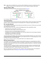
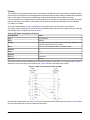
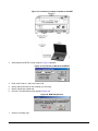
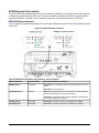
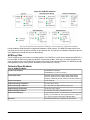
Figure 24 shows the location and designation of the LED status indicators on the NCM. Table 8 describes the purpose
of each LED.
Figure 24: NCM LED Status Indicators
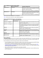
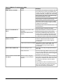
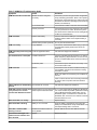
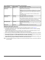
Table 8: NCM LED Designations, Normal Status, and Descriptions
LED Designation
Normal Status
Descriptions/Other Conditions
POWER (Green)
On Steady
On Steady = Unit is getting power from either the battery or 24 VAC
power.
Off Steady = Unit is shut down.
ETHERNET (Green)
Blinking
Blinking = Data is transferring on the Ethernet connection. Ethernet
traffic is general traffic (may not be for the NCM).
Off Steady = No Ethernet traffic, probably indicates a dead Ethernet
network or bad Ethernet connection.
10/LINK (Green)
On Steady
On Steady = Ethernet connection is established at 10 Mbps.
100/LINK (Green)
On Steady
On Steady = Ethernet connection is established at 100 Mbps.
NCM45x0-2 Network Control Module Commissioning Guide
32