1
Note: A high %idle for a NCM4500 does not indicate that the NCM45x0 can support more field devices than a
NCM350, and does not ensure reasonable service time with an Network Integration Engine (NIE).
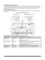
System Status LEDs
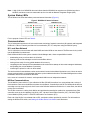
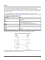
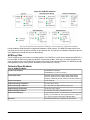
The NCM has nine LEDs that indicate power and status information (Figure 3).
Figure 3: NCM45x0-2 Status Indicators
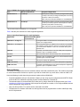
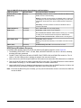
For the purpose of each LED, see Table 8.
Communications
The I/O subsystem supports a multi-user environment consisting of network connections (N1 network and integrated
N2 Bus or LONWORKS network) and direct I/O communication (OT, NT, and printer using the RS232C ports).
N1 Local Area Network
The N1 LAN allows communication with both OWSs and other NCMs on the network. The Ethernet circuitry is built
into the NCM45x0-2 motherboard.
Each NCM and OWS on the system contains a Node Manager task, whose responsibilities include:
•
•
•
•
•
broadcasting once per minute that it is still online
listening to other node managers to track on and offline devices
issuing a time stamp for every global database in its memory
comparing the time stamps of its own databases to the received time stamps of other node managers’ databases,
and updating the current database if necessary
monitoring the printer for online or offline status
The device with the lowest address number on the network issues time and date information every 4 hours to ensure
system synchronization. A clock/calendar chip backs up time and date information. This Node Manager also monitors
broadcasts and issues online/offline advisories.
In the event of a severed N1 network, each separated LAN forms an independent network.
N2 Bus Communications
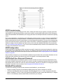
The NCM4510-2 has a built-in FC bus called the N2 Bus (RS-485) that allows it to communicate with a variety of
field controllers. Devices on the N2 Bus constitute a local network, controlled by the NCM. The NCM polls the devices
according to a user-set priority level, which is set at the Definition window at each device. In most cases, the default
priority level is sufficient.
The N2 Bus connects in a daisy-chain fashion and provides the transmission medium for external devices (field
controllers such as the Air Handling Unit (AHU), UNT, Lab and Central Plant Controller (LCP), DX-9100, Digital
Control Module (DCM), and IFC-1010/IFC-2020 Indoor Fan Contractor (IFC).
Each end of the N2 Bus is terminated with an EOL termination resistor provided by a switch. For information on
setting the N2 Bus EOL switch, see Setting the N2 Bus End-of-Line Switch in this document.
NCM45x0-2 Network Control Module Commissioning Guide
7