1
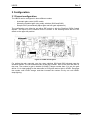
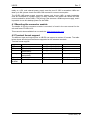
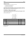
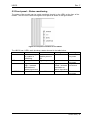
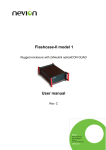
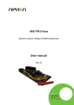
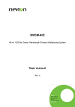
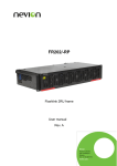
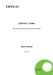
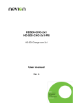
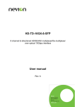
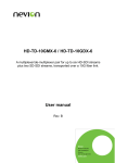
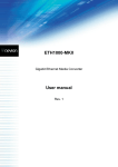
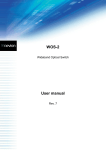
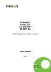
LB-EO L-BAND Electrical to Optical Converter User manual Rev. F Nevion Nordre Kullerød 1 3241 Sandefjord Norway Tel: +47 33 48 99 99 nevion.com LB-EO Rev. F Nevion Support Nevion Europe Nevion USA P.O. Box 1020 3204 Sandefjord, Norway Support phone 1: +47 33 48 99 97 Support phone 2: +47 90 60 99 99 1600 Emerson Avenue Oxnard, CA 93033, USA Toll free North America: (866) 515-0811 Outside North America: +1 (805) 247-8560 E-mail: [email protected] See http://www.nevion.com/support/ for service hours for customer support globally. Revision history Current revision of this document is the uppermost in the table below. Rev. Repl. Date Sign Change description F 5 5 4 2014-01-15 2011-02-21 AJM AA 4 3 2008-04-01 GMW 3 2 2007-11-02 GMW 2 1 2007-09-25 GMW 1 0 A 0 A - 2007-07-04 2007-03-29 2006-05-01 GMW GMW GMW Removed 8 discontinued lasers. New template. Updated Declaration of Conformity. Removed Chapter 2.4 (Environmental conditions). Added connector interface description and more application details in product overview. Added 6 CWDM channels. Added Declaration of Conformity. Added new product LB-EO-13T 0dBm. Added Materials Declaration and EFUP. Changed optical budget to 16dB for 15T/CWDM and 6dB for 13T Added specifications for LB-EO-13T First official version Preliminary version nevion.com | 2 LB-EO Rev. F Contents Revision history ........................................................................................................ 2 1 Product overview ................................................................................................... 4 2 Specifications ........................................................................................................ 6 2.1 RF Characteristics......................................................................................................... 6 2.2 Optical Characteristics .................................................................................................. 6 2.3 Power connection.......................................................................................................... 6 3 Configuration ......................................................................................................... 7 3.1 Format configuration ..................................................................................................... 7 4 Connections .......................................................................................................... 9 4.1 Mounting the connector module ...................................................................................10 4.2 Terminal format support ...............................................................................................10 5 Module status ...................................................................................................... 11 5.1 GPI Alarm – Module status outputs ..............................................................................11 5.2 Front panel – Status monitoring ...................................................................................12 6 Laser safety precautions ..................................................................................... 13 General environmental requirements for Nevion equipment .................................. 14 Product Warranty.................................................................................................... 15 Appendix A Materials declaration and recycling information .................................. 16 A.1 Materials declaration ....................................................................................................16 A.2 Recycling information...................................................................................................16 nevion.com | 3 LB-EO Rev. F 1 Product overview The Flashlink LB-EO is an electrical to fiber optical converter module providing high performance media conversion for analogue signals with bandwidth from 950 to 2150 MHz. This state of the art unit offers low noise amplifiers and a high quality laser diode technology with low distortion and capable of amplifying large signal levels. The attenuator is a high performance digitally controlled device, giving low distortion and flat frequency response. The Flashlink LB-EO is therefore the first choice for all optical transport demands on L-band. The Flashlink LB-EO converter and the Flashlink LB-OE converter can transport all L-band signals between 950 and 2150 MHz over long distances using fiber optical transport media. The optical output comes with a sophisticated wideband laser diode designed to convert the electrical signal to optical giving very little inter modulation and excellent signal to noise ratio. There is also an attenuated electrical monitor output for test and service purposes as well as a remote control interface. Figure 1: LB-EO L-band electrical to optical converter. This L-band link is normally used in conjunction with other equipment like satellite tuners, LNBs in parabolic dishes etc, and the link performance is dependant of good signal to noise ratio from the signal source and good noise figure of the receiver equipment. The link quality is also dependant of the number of channels transferred on the link. For instance, the link’s signal to noise ratio is reduced with 3dB when doubling the number of the channels (twice the power). An optical link will add some noise to the signal. The amount of noise is dependant of the fiber loss, the satellite receiver sensitivity, number of channels and the total power level of the signal. The combination if analogue and digital satellite signals is also important. Many analogue satellite signals (which tend to have higher power), will reduce the signal to noise ratio on the digital signals. This is because the link’s power must be reduced according to the total power of the link. Noise figure of the link is a number usually in dB that states how much the signal to noise ratio (S/N ratio) is reduced from the input to the output. If the S/N ratio from the dish is X dB, the noise figure on the link is Y dB, the S/N ratio on the output will be X-Y dB. Dependant on the application (fiber loss, total power on signal and power of the laser), one link will typically add 4-5dB noise for fiber distances less than 3000 meters. A coaxial cable will attenuate more on higher frequencies than lower. If the attenuation on 2GHz is more than the noise figure for the L-band link, there will be a system improvement nevion.com | 4 LB-EO Rev. F regarding total signal to noise ratio. Therefore, to distance from the dish to the receiver must be significant (more than 200 meters, dependant of the coaxial cable specification) for getting return of the investment of the L-band link. If the application needs galvanic isolation, the L-band link is a very good way to achieve this. It is recommended that the wavelengths 1590 and 1610 nm are reserved for digital communication in CWDM systems due to fiber distortion issues (see fiber specification). nevion.com | 5 LB-EO Rev. F 2 Specifications 2.1 RF Characteristics Frequency band width Return loss RF interface Gain flatness Maximum usable input signal Maximum input signal without damage Inter modulation products (two carriers, 5dB optical loss) Link gain Optical link budget 1dB compression (output) Noise figure Carrier to noise ratio (CNR)with maximum input power Spurious free dynamic range (SFDR) – input signal level -25dBm 950-2150 MHz >10dB F-connector ±1.5dB over entire band ±0.25dB at any 36 MHz < -5dBm >+10dBm < -55dBc (15T/CWDM) < -45dBc (13T) 40dB 16dB/50km (15T/CWDM) 6dB (13T) 0dBm <10dB @ 3dB fiber optical loss <20dB @ 16dB fiber optical loss >45dB @ 36MHz (15T/CWDM) >35dB @ 36MHz (13T) >110dBc/Hz 2.2 Optical Characteristics Wavelength 1310nm ±40nm, 8 CWDM channels ±2nm , (1470, 1490, 1510, 1530, 1550, 1570, 1590 and 1610 nm) Power output +3dBm (15T/CWDM) 0dBm or -3dBm (13T) SC/UPC, Single mode Optical interface 2.3 Power connection Maximum power consumption <3W (+5V) <1.5W (-15V) <1.5W (+15V) nevion.com | 6 LB-EO Rev. F 3 Configuration 3.1 Format configuration The LB-EO can be configured in three different modes: Automatic gain control (AGC mode) Manually controlled gain using rotary switches (SW2 and SW3) Sample AGC (automatically adjust gain and lock gain adjustment) The configuration can either be set with a DIP switch or with the Flashlink GYDA Control System. The layout of the Flashlink LB-EO is shown in the drawing below with the DIP switch to the upper left position. Figure 2: LB-EO board layout. For setting the gain manually, use the rotary switches SW2 and SW3 situated near the extractor handle. The two switches make a two digit number. SW3 is the tens and SW2 is the ones. The number is gain in decibel (0-31dB). If larger number than 31 is set, the gain will be 31. An ideal setting for the attenuator is LOS green and no light in LEVEL. Decrease the number until LEVEL orange, and then increase the number one by one until LEVEL stops lighting. nevion.com | 7 LB-EO Rev. F DIP switch configuration must be set according to the table below: Switch # 1 Label AGC 2 R/S 3 LNB 4 H/V 5 LLC 6 7 H/L GPI 8 OVR Function, DIP = ON Automatic gain control Run AGC Function, DIP = OFF Manual gain control Enable power supply for LNB Horizontal polarization Line length compensation on Disable power supply for LNB Vertical polarization High band H/V and H/L controlled by GPI Low band H/V and H/L controlled by DIP or GYDA GYDA control. Config. with GYDA Sample AGC level Line length compensation off Comment Only valid in Manual gain control Sets voltage on LNB If on, output voltage from card to LNB will increase by 1 volt. Set to ON when using long cables (cable more than approx 3 ohms DC resistance in cable) 22kHz tone control When GPI is set, DIP 4 and 6 will be disregarded Override GYDA Select configuration from control. Config. GYDA with DIP switch All DIP switches are off when pointing towards the release handle. nevion.com | 8 LB-EO Rev. F 4 Connections The Flashlink LB-EO has a dedicated connector module: LB-EO-C1. This module is mounted at the rear of the sub-rack. The module is shown in the figure below. Monitor output Fiber optical RF input LNB power supply GPI Figure 3: Connector module for L-band. In typical use, an LB-EO / LB-OE module at each end will be used. An LNB is connected to the F-connector of the LB-EO, and a satellite tuner is connected to the F-connector of the LB-OE. The voltage/22kHz output from the satellite tuner, can not be transferred on the fiber between LB-EO and LB-OE, because this signal goes the other way. The LB-OE can nevertheless detect voltage and/or tone, and put them to the GPI output on the LB-EO. Using a separate communication line (two digital signals using D422MG or similar), these signals can be transferred to the LB-EO. LB-EO tone/voltage output on the RF-connector can be controlled is three different ways: directly using GYDA, DIP switches or the GPI inputs (see chapter 3.1 for DIP switch settings). The LB-OE will always detect the voltage/tone from the satellite tuner or other equipment, and set the GPI according to the detected tone and voltage. A 22 kHz tone on top of the LNB power supply indicates high band (11.7-12.75 GHz) and no tone is for low band (10.711.7 GHz). Vertical polarization is chosen with a voltage less than 15 volts, typically 13 volts. Most LNBs will set vertical polarization within a voltage window (for instance from 11.5 to 14.2 volts dependant of the LNB). Accordingly the horizontal polarisation is voltage greater than 15 volts, typically 18 volts (for instance from 15.8 to 19.0 volts). If the voltage is near 15 (for instance between 14.2 and 15.8), the polarization will be uncertain. The example voltages are LNB manufacturer dependant, please check the user manual for the LNB voltage thresholds. If the RF coaxial cable is long, there will be a DC loss. By adding one volt out from the LB-EO, longer cables can be used without risking getting the wrong polarization. This configuration is called LLC (long line compensation). There is also a power connection for LNB. Connect pin 4 to a positive voltage (+12V to +24V) and pin 1 to power supply ground. The frame power supply can only supply 15W nevion.com | 9 LB-EO Rev. F totally on +15V, and external power supply must be used if 15W is exceeded. LNBs can draw up to 9W, please check the LNB’s user manual for current consumption. The LB-EO LNB power supply connector powers only its own LNB, so each backplane must be connected to a power supply (or daisy chained if the power can handle the total current needed for all the LNBs). The pinning is the same as a Sublime power supply, and it is possible to use this desktop power for the LNBs. 4.1 Mounting the connector module The details of how the connector module is mounted, is found in the user manual for the sub-rack frame FR-2RU-10-2. This manual is also available from our web site: http://www.nevion.com/ 4.2 Terminal format support The different input and output ports on LB-EO can support a number of formats. The table below shows which signal formats are supported on the selected terminals. Terminal format support: Terminal OPT RF Monitor GPI Input GPI Output GPI ALARM Function Optical output Electrical input Electrical output (attenuated) Control High/low band and polarity Data Output Open Collector Alarms Supported Format Analogue 950-2150 MHz Analogue 950-2150 MHz Analogue 950-2150 MHz Mode Output Input Output Digital input CMOS Input Digital output Wired alarms Open collector output Open Collector Output nevion.com | 10 LB-EO Rev. F 5 Module status The status of the module can be monitored in three ways. 1. GYDA System Controller (optional). 2. GPI at the rear of the sub-rack. 3. LED’s at the front of the sub-rack. Of these three, the GPI and the LED’s are mounted on the module itself, whereas the GYDA System Controller is a separate module giving detailed information on the card status. The functions of the GPI and the LED’s are described in sections 5.1 and 5.2. The GYDA controller is described in a separate user manual. 5.1 GPI Alarm – Module status outputs These outputs can be used for wiring up alarms for third party control systems. The GPI outputs are open collector outputs, sinking to ground when an alarm is triggered. The GPI connector is shown in figure below. LB-EO module GPI pinning: Figure 4: GPI output. Signal Status LOS LEVEL H/L Name General error status for the module Loss of Signal (open = signal detected) Level too high (open = level ok) High/low band (ground for 22kHz tone enable/high band) H/V Horizontal/vertical polarization (ground for vertical polarisation) DATA Data output Ground 0 volt pin Electrical Maximums for GPI outputs Pin # Pin 1 Pin 2 Pin 3 Pin 4 Mode Open Collector Open Collector Open Collector CMOS Input Pin 5 CMOS Input Pin 6 Pin 8 Open Collector 0V. Max current: 100 mA Max voltage: 30 V nevion.com | 11 LB-EO Rev. F 5.2 Front panel – Status monitoring The status of the module can be easily monitored visually by the LED’s at the front of the module. The LED’s are visible through the front panel as shown in the figure below. Figure 5: Front panel indicators for the LB-EO. The LB-EO has 4 LED’s each showing a status showed in the table below. Diode / State STATUS LOS LEVEL LASER FAIL Red LED Module is faulty, or module is initialising. No signal Signal level too high – increase attenuation or reduce input level Laser failure Green LED Module is OK Module power is OK Signal is present Orange LED Signal level critical - increase attenuation or reduce input level Laser OK No light Module has no power Module has no power Signal level not critical Module has no power nevion.com | 12 LB-EO Rev. F 6 Laser safety precautions These are guidelines to limit hazards from laser exposure. All the available EO units in the Flashlink range include a laser. Therefore this note on laser safety should be read thoroughly. The lasers emit light at wavelengths from 1470nm up to 1610nm. This means that the human eye cannot see the beam, and the blink reflex cannot protect the eye. (The human eye can see light between 400 nm to 700 nm). A laser beam can be harmful to the human eye (depending on laser power and exposure time). Therefore: Be careful when connecting / disconnecting fiber pigtails (ends). Never look directly into the pigtail of the laser/fiber. Never use microscopes, magnifying glasses or eye loupes to look into a fiber end. Use laser safety goggles blocking light at 1310 nm and at 1550 nm Instruments exist to verify light output power: Power meters, IR-cards etc. Flashlink features: All the laser module cards in the Flashlink product range, are Class 1 laser products according to IEC 825-1 1993, and class I according to 21 CFR 1040.10 when used in normal operation. More details can be found in the user manual for the FR-2RU-10-2 frame. Maximum output power1: 5 mW Operating wavelengths: > 1470 nm 1 Max power is for safety analysis only and does not represent device performance. nevion.com | 13 LB-EO Rev. F General environmental requirements for Nevion equipment 1. 2. - The equipment will meet the guaranteed performance specification under the following environmental conditions: Operating room temperature range: 0°C to 40°C Operating relative humidity range: <90% (non-condensing) The equipment will operate without damage under the following environmental conditions: Temperature range: -10°C to 50°C Relative humidity range: <95% (non-condensing) nevion.com | 14 LB-EO Rev. F Product Warranty The warranty terms and conditions for the product(s) covered by this manual follow the General Sales Conditions by Nevion, which are available on the company web site: www.nevion.com nevion.com | 15 LB-EO Rev. F Appendix A Materials declaration and recycling information A.1 Materials declaration For product sold into China after 1st March 2007, we comply with the “Administrative Measure on the Control of Pollution by Electronic Information Products”. In the first stage of this legislation, content of six hazardous materials has to be declared. The table below shows the required information. Toxic or hazardous substances and elements 組成名稱 Part Name LB-EO 鉛 汞 镉 六价铬 多溴联苯 Lead Mercury Cadmium Hexavalent Polybrominated (Pb) (Hg) (Cd) Chromium biphenyls (Cr(VI)) (PBB) O O O O O 多溴二苯醚 Polybrominated diphenyl ethers (PBDE) O O: Indicates that this toxic or hazardous substance contained in all of the homogeneous materials for this part is below the limit requirement in SJ/T11363-2006. X: Indicates that this toxic or hazardous substance contained in at least one of the homogeneous materials used for this part is above the limit requirement in SJ/T11363-2006. This is indicated by the product marking: A.2 Recycling information Nevion provides assistance to customers and recyclers through our web site http://www.nevion.com/. Please contact Nevion’s Customer Support for assistance with recycling if this site does not show the information you require. Where it is not possible to return the product to Nevion or its agents for recycling, the following general information may be of assistance: Before attempting disassembly, ensure the product is completely disconnected from power and signal connections. All major parts are marked or labeled to show their material content. Depending on the date of manufacture, this product may contain lead in solder. Some circuit boards may contain battery-backed memory devices. nevion.com | 16