1
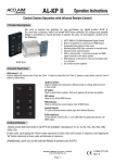
V Power
VP-60
VP-120
User Manual
Please read the instructions carefully before use
VP-60/120
TABLE OF CONTENTS
EC - Declaration of Conformity
1. Safety Instruction
We declare that our products (lighting equipments) comply with the following
2. Features
specification and bears CE mark in accordance with the provision of the
3. Technical Specification
Electromagnetic Compatibility (EMC) Directive 89/336/EEC.
EN55014-2: 1997 A1: 2001, EN61000-4-2: 1995; EN61000-4-3: 2002;
4. Installing Instructions
EN61000-4-4: 1995; EN61000-4-5: 1995, EN61000-4-6: 1996,
5. Main Function
EN61000-4-11: 1994.
6. Overview
&
6.1 Front View
6.2 Rear View
Harmonized Standard
EN60598-1: 2000+ALL: 2000+A12: 2002
7. DMX Controller
Safety of household and similar electrical appliances
8. DMX512 Configuration
Part 1: General requirements
9. DMX512 Connection
9.1 XLR Connection
9.2 RJ45 Connection
1A
VP-60/120
9.1 RJ45 Connection
VP-60/120
1. Safety Introductions
Please read the User Manual carefully as it includes important information regarding
details of operation, maintenance and technical data. Keep this manual with unit for
future consultation.
WARNING!
DMX Input, Output
RJ45 Connector
Front view of the Connector
● Avoiding any flammable liquids, water or metal objects enter into the unit.
LED module Input
● If any liquid spill on the unit, disconnect the power supply immediately.
RJ45 Connector
Front view of the Connector
● When serious operation problem happen, stop using the unit immediately and
contact your local dealer for service.
● Do not open the unit because there are no user serviceable parts inside.
● Never try to repair the unit yourself. Repairs by unqualified people could cause
damage or faulty operation. Please contact your nearest dealer for any service.
Pin 1: Not connected Pin 5: Not connected
Pin 1: Red LED +
Pin 5: Red LED -
Pin 2: Not connected Pin 6: Data +
Pin 2: Green LED + Pin 6: Green LED -
Pin 3: Not connected Pin 7: Data -
Pin 3: Blue LED +
Pin 7: Blue LED -
Pin 4: Not connected Pin 8: GND
Pin 4: White LED +
Pin 8: White LED -
CAUTION!
● After removed the package, make sure the unit is not damaged in any way. Don’t
use it with doubt and contact an authorized dealer.
● Never use the unit under the excessive humidity and a temperature over 40℃.
● Do not try to dismantle or modify the unit.
2. Features
● 7 Channel modes enables V Power to control passive lighting fixtures that fitted with
different LED emitters.
● Comes with 16 built-in programs under Master/Slave mode. 3 user editable chases,
each chase up to 42 scenes.
● Under Manual mode, user can adjust each color’s intensity to get the best color
mixing effects.
● White Balance setup-User can adjust the pre-set White Balance of the V Power.
● Smooth fade in/fade out effect.
● It can be controlled by the LED Remote Commander (LED-RC).
● LED display for easy navigation.
17A
2A
VP-60/120
3. Technical Specifications
VP-60/120
9. DMX512 Connection
y DMX Input
9.1 XLR Connection
Control: DMX 512
DMX connection: RJ45 or 3 pin XLR
y DMX Output
Max. Power Output: 60W (VP-60) / 120W(VP-120)
Output Voltage: DC 48V
Max. Output Current: 350mA per color
Max. Load per zone: RGB & RGBW mode-Each color 12 LEDs max.
White mode-Each white 24 LEDs max.
y Input Voltage: AC 100V-240V~50/60Hz
y Fuse: T 1A (VP-60)
T 2A (VP-120)
1. If you using a controller with 5 pins DMX output, you need to use a 5 to 3 pin
y Dimension: 215×179×61 mm (VP-60)
adapter-cable.
279×234×61 mm (VP-120)
2. At last unit, the DMX cable has to be terminated with a terminator. Solder a 120
y Weight:1.2kgs (VP-60)
ohm 1/4W resistor between pin 2(DMX-) and pin 3(DMX+) into a 3-pin XLR-plug
2.1kgs (VP-120)
and plug it in the DMX-output of the last unit.
3. Connect the unit together in a `daisy chain` by XLR plug from the output of the unit
to the input of the next unit. The cable can not branched or split to a `Y` cable.
DMX 512 is a very high-speed signal. Inadequate or damaged cables, soldered
joints or corroded connectors can easily distort the signal and shut down the
system.
4. The DMX output and input connectors are pass-through to maintain the DMX
circuit, when one of the units’ power is disconnected.
5. Each unit needs to have an address set to receive the data sent by the controller.
The address number is between 0-511 (usually 0 & 1 are equal to 1).
6. The end of the DMX 512 system should be terminated to reduce signal errors.
7. 3 pin XLR connectors are more popular than 5 pin XLR.
3 pin XLR: Pin 1: GND, Pin 2: Negative signal (-), Pin 3: Positive signal (+)
5 pin XLR: Pin 1: GND, Pin 2: Negative signal (-), Pin 3: Positive signal (+),
Pin 4/Pin 5: not used.
3A
16A
VP-60/120
VP-60/120
4. Installing instructions
The VP-60/120 should be placed on a non-flammable flat surface in any orientation
and fixed by the two screws. There are two mounting holes on the housing. Ensure
that installation place is enough ventilated.
V Power could control the LED fixtures such as V Aqua, V Bar, V Ceiling, V Inground,
V Net, V Wall and CW36, the VP-60 power output is 60 watt and the VP-120 power
output is 120 watt.
15A
4A
VP-60/120
VP-60/120
5. Main Function
To select any function, press MENU button until the required one is shown on the
display. Select the function by ENTER button and the display will blink. Use DOWN
and UP button to change the mode. Once the required mode has been selected,
press ENTER button to setup (or it will automatically return to the main functions
without any change after idling one minute). Back to the functions without any change
press MENU button. The main functions are shown below:
5A
14A
VP-60/120
VP-60/120
DMX 512 Address Setting
Press the MENU button up to when the
is shown on the display. Pressing
ENTER button and the display will blink. Use DOWN and UP button to change the
DMX 512 address from 1 to 512. Once the address has been selected, press ENTER
button to setup (or automatically return to the main functions without any change after
idling one minute). Back to the previous function without any change press MENU
button.
Channel Mode
Press the MENU button up to when the
is shown on the display. Pressing
ENTER button and the display will blink. Use DOWN and UP button to select the
(11 channels) or
(8 channels)…or
(2 Channels) mode.
Once the mode has been selected, press the ENTER button to setup (or automatically
VP-120:
return to the main functions without any change after idling one minute). To go back to
the previous function without any change press the MENU button.
Show
Press the MENU button up to when the
is showing on the display. Pressing
ENTER button and the display will blink. Use DOWN and UP button to select the
(show 1) or
… or
(show 19). Once the show has been
selected, press the ENTER button and use DOWN and UP button to set fade time
(0-255: 0.256s-66847s) and wait time(0-255:0.256s-66847s), once selected, press
ENTER button to store (or automatically return to the main functions without any
change after idling one minute). To go back to the previous function without any
change press the MENU button.
Blackout Mode
Press the MENU button up to when the
is showing on the display. Pressing
ENTER button and the display will blink. Use DOWN and UP button to select the
(yes blackout) or
(no blackout) mode. Once selected, press the
ENTER button to setup(or automatically return to the main functions without any
change after idling one minute). To go back to the previous function without any
change press the MENU button.
13A
6A
VP-60/120
Program Show
8. DMX512 Configuration
is showing on the display. Pressing
Press the MENU button up to when the
ENTER button and the display will blink. Use DOWN and UP button to select the
(show 17) or
VP-60/120
(show 18)or
VP-60:
(show 19). Once the show has
been selected, press the ENTER button to enter setting program. You can select
(length, the steps, you choose from the total amount of steps, you want to run,
for example, if the total amount of steps you set is 42, you can choose only first 1-10
(step), select
steps to run).
to set
(color: 0-255, 1 for zone 1, 2 for zone 2 ),
or
,
or
or
,
,
(white) and
(dimmer) for every step. Automatically return to the main
functions without any change after idling one minute. To go back to the previous
function without any change press the MENU button.
NOTE: For VP-120, when you selected channel mode 5 or 6, you can set only
,
(color, 1 for zone 1, 2 for zone 2) and
,
(dimmer) for every step. When you selected channel mode 7, you can set only
,
(dimmer) for every step.
Manual Mode
Press the MENU button up to when the
is showing on the display. Pressing
ENTER button and the display will blink. Use DOWN and UP button to select the
or
,
or
(green),
(white),
(red, 1 for zone 1, 2 for zone 2 ),
or
,
(dimmer),
(blue),
or
or
,
,
(strobe) mode. Once selected, press
the ENTER button to setup (or automatically return to the main functions without any
change after idling one minute). To go back to the previous function without any
change press the MENU button.
Adjust White Balance
Press the MENU button up to when the
is showing on the display. Pressing
ENTER button and the display will blink. Use DOWN and UP button to select the
or
,
(red: 125-255, 1 for zone 1, 2 for zone 2 ),
or
7A
12A
VP-60/120
VP-60/120
,
11 Channels:
(green),
or
,
(blue) mode. Once selected,
press the ENTER button to store (or automatically return to the main functions without
any change after idling one minute). To go back to the previous function without any
8 Channels:
change press the MENU button.
6 Channels:
Self-Test
Press the MENU button up to when the
7 Channels:
is blinking on the display. Pressing
ENTER button and the unit will run self-test by built-in program. To go back to the main
functions press the MENU button again.
4 Channels:
LED
3 Channels:
Press the MENU button up to when the
is shown on the display. Pressing
ENTER button and the display will blink. Use DOWN and UP button to select the
2 Channels:
(LED display ON) or
( LED display OFF) mode. Once selected, press
ENTER button to setup (or automatically return to the main functions without any
1 Channel:
change after idling one minute). To go black to the previous function without any
change press MENU button.
Fixture Hours
Press the MENU button up to when the
is blinking on the display. Pressing
ENTER button and the display will show the number of working hours of the unit. To
go back to the main functions press the MENU button.
Software version
Press the MENU button up to when the
is blinking on the display. Pressing
ENTER button and the display will show the version of software of the unit. To go back
to the previous function press the MENU button.
11A
8A
VP-60/120
6. Overview
VP-60/120
6.2 Rear View
VP-60:
6.1 Front View
VP-120
LED
1. POWER
Power cable for AC input
2. FUSE
For protecting the unit when the transient current is too big
1. DMX
On
DMX Input
2. MASTER
On
Master Mode
3. DMX OUT
DMX Output RJ45 or 3 pin XLR socket
3. SLAVE
On
Slave Mode
4. DMX IN
DMX input RJ45 or 3 pin XLR socket
4. POWER
On
Power on
5. LED
DC power & signal output for linking LED fixtures
5. Display
To show the various menu and selected function
6. Menu
Press the button to select the programming functions.
7. Down
Press the button to go backward for the desired functions.
7. DMX Controller
8. Up
Press the button to go forward for the desired functions.
Using universal DMX controller to control the units, you have to set DMX address from
9. Enter
Press the button to confirm the selected functions.
1 to 512 so that the units can receive DMX signal.
Press the MENU button up to when the
is showing on the display. Pressing
ENTER button and the display will blink. Use DOWN and UP button to change the
DMX512 address. Once the address has been selected, press ENTER button to store
(or it will automatically return to the main functions without any change after idling one
minute). To go back to the main functions without any change press the MENU button.
Please refer to the following diagram to address your DMX512 channel for the first 4
units.
9A
10A