1
AC Servo Drives
Σ -V Series
USER'S MANUAL
CANopen Network Module
SGDV-OCB01A
To properly use the product, read this manual thoroughly
and retain for easy reference, inspection and maintenance.
Ensure the end user receives this manual.
1
2
3
4
1
2
3
4
Please check www.yaskawa.eu.com for up-to-date versions.
5
6
MANUAL NO. YEU SIEP C720829 20A
Copyright © 2012 YASKAWA EUROPE GmbH
All rights reserved. No part of this publication may be reproduced, stored in a
retrieval system, or transmitted, in any form, or by any means, mechanical,
electronic, photocopying, recording, or otherwise, without the prior written
permission of Yaskawa. No patent liability is assumed with respect to the use of
the information contained herein. Moreover, because Yaskawa is constantly
striving to improve its high-quality products, the information contained in this
manual is subject to change without notice. Every precaution has been taken in
the preparation of this manual. Nevertheless, Yaskawa assumes no
responsibility for errors or omissions. Neither is any liability assumed for
damages resulting from the use of the information contained in this publication.
About this manual
This manual describes the operation of the SGDV-OCB01A CANopen network
module with the S-V Series servo drive. For a more complete understanding of
the S-V Series capabilities and features, refer to the related manuals.
Be sure to refer to this manual and perform operations correctly.
Keep this manual in a location where it can be accessed for reference
whenever required.
This manual contains the following chapters:
Chapter 1:
Introduces the product specification and technical data.
Chapter 2:
Describes the installation and configuration of the hardware
and communication.
Chapters 3 - 5:
Describes the communication, PDOs and SGDV objects.
Chapter 6:
Describes the device control.
Chapters 7 - 13:
Describes the motion related objects in various modes of
operation and the profile motion parameters.
Chapter 14:
I/O: Describes how to read and set analog or digital inputs/
outputs.
Chapter 15:
Describes error messages and error handling.
Chapter 16:
Provides examples.
Chapter 17:
Describes the data types.
Chapter 18:
Lists the SGDV-OCB01A objects based on EDS.
IMPORTANT explanations
The following icon is displayed for explanations requiring special attention.
• Indicates important information that should be memorized,
as well as precautions, such as alarm displays, that do not
involve potential damage to equipment.
IMPORTANT
iii
Notation used in this manual
In this manual, the names of reverse signals (ones that are valid when low)
are written with a forward slash (/) before the signal name, as shown in the
following example:
Example
S-ON = /S-ON
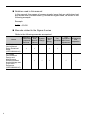
Manuals related to the Sigma-5 series
Refer to the following manuals as required.
Name
-V Series
User's Manual
Setup Rotational
Motor
(SIEPS800000 43)
-V Series
User's Manual
Design and
Maintenance
Rotational Motor/
Analog Voltage and
Pulse Train
Reference
(SIEPS800000 45)
iv
Selecting Ratings
Models and
and
System
Peripheral Specifi- Design
Devices
cations
Trial
Panels
Maintenance
Trial
Operation
and
and
Operation and Servo
Wiring
Inspection
Adjustment
Safety information
The following conventions are used to indicate precautions in this manual.
Failure to heed precautions provided in this manual can result in serious or
possibly even fatal injury or damage to the products or to related equipment
and systems.
WARNING
Indicates precautions that, if not heeded, could
possibly result in loss of life or serious injury.
CAUTION
Indicates precautions that, if not heeded, could result
in relatively serious or minor injury, damage to the
product, or faulty operation.
In some situations, the precautions indicated could
have serious consequences if not heeded.
PROHIBITED
MANDATORY
Indicates prohibited actions that must not be
performed. For example, this symbol would be used to
indicate that fire is prohibited as follows:
Indicates compulsory actions that must be performed.
For example, this symbol would be used as follows to
indicate that grounding is compulsory:
v
Safety precautions
These safety precautions are very important. Read them before performing
any procedures such as checking products on delivery, storage and
transportation, installation, wiring, operation and inspection, or disposal. Be
sure to always observe these precautions thoroughly.
WARNING
• Never touch any rotating motor parts while the motor is running.
Failure to observe this warning may result in injury.
• Before starting operation with a machine connected, make sure that an
emergency stop can be applied at any time.
Failure to observe this warning may result in injury or damage to the product.
• Never touch the inside of the SERVOPACKs.
Failure to observe this warning may result in electric shock.
• Do not remove the cover of the power supply terminals while the power is ON.
Failure to observe this warning may result in electric shock.
• After the power is turned OFF or after a voltage resistance test, do not
touch terminals while the CHARGE lamp is ON.
Residual voltage may cause electric shock.
• Follow the procedures and instructions provided in this manual for trial
operation.
Failure to do so may result not only in faulty operation and damage to equipment, but
also in personal injury.
• The multi-turn output range for the S-V Series absolute position detecting
system is different from that of earlier systems (15-bit and 12-bit encoders).
In particular, change the system to configure the S series infinite-length
positioning system with the S-V Series.
• The multi-turn limit value needs not be changed except for special
applications.
Changing it inappropriately or unintentionally can be dangerous.
• If the Multi-turn Limit Disagreement alarm occurs, check the setting of
parameter Pn205 in the SERVOPACK to be sure that it is correct.
If Fn013 is executed when an incorrect value is set in Pn205, an incorrect value will be
set in the encoder. The alarm will disappear even if an incorrect value is set, but
incorrect positions will be detected, resulting in a dangerous situation where the
machine will move to unexpected positions.
• Do not remove the front cover, cables, connectors, or optional items from
the upper front of the SERVOPACK while the power is ON.
Failure to observe this warning may result in electric shock.
• Do not damage, press, exert excessive force on, or place heavy objects on
the cables.
Failure to observe this warning may result in electric shock, stopping operation of the
product, or fire.
• Do not modify the product.
Failure to observe this warning may result in injury, fire, or damage to the product.
vi
WARNING
• Provide an appropriate stopping device on the machine side to ensure
safety. The holding brake on a servomotor with a brake is not a stopping
device for ensuring safety.
Failure to observe this warning may result in injury.
• Do not come close to the machine immediately after resetting a momentary
power loss. The machine may restart unexpectedly. Take appropriate
measures to ensure safety against an unexpected restart.
Failure to observe this warning may result in injury.
• Connect the ground terminal according to local electrical codes (100 W or
less for a SERVOPACK with a 100, 200 V power supply. 10 W or less for a
SERVOPACK with a 400 V power supply.)
Improper grounding may result in electric shock or fire.
• Installation, disassembly, or repair must be performed only by authorized
personnel.
Failure to observe this warning may result in electric shock or injury.
• The person who designs a system using the safety function (Hard Wire
Baseblock function) must have full knowledge of the related safety
standards and full understanding of the instructions in S-V Series User’s
Manual Design and Maintenance (SIEP S800000 45/46).
Failure to observe this warning may result in injury or damage to the product.
Storage and transportation
CAUTION
• Do not store or install the product in the following locations.
Failure to observe this caution may result in fire, electric shock, or damage to the product.
• Locations subject to direct sunlight
• Locations subject to temperatures outside the range specified in the storage/
installation temperature conditions
• Locations subject to humidity outside the range specified in the storage/installation
humidity conditions
• Locations subject to condensation as the result of extreme changes in
temperature
• Locations subject to corrosive or flammable gases
• Locations subject to dust, salts, or iron dust
• Locations subject to exposure to water, oil, or chemicals
• Locations subject to shock or vibration
• Do not hold the product by the cables, motor shaft or detector while
transporting it.
Failure to observe this caution may result in injury or malfunction.
• Do not place any load exceeding the limit specified on the packing box.
Failure to observe this caution may result in injury or malfunction.
vii
Storage and transportation (cont’d)
CAUTION
• If disinfectants or insecticides must be used to treat packing materials such
as wooden frames, pallets, or plywood, the packing materials must be
treated before the product is packaged, and methods other than fumigation
must be used.
• Example: Heat treatment, where materials are kiln-dried to a core
temperature of 56C for 30 minutes or more.
If the electronic products, which include stand-alone products and products installed
in machines, are packed with fumigated wooden materials, the electrical components
may be greatly damaged by the gases or fumes resulting from the fumigation process.
In particular, disinfectants containing halogen, which includes chlorine, fluorine,
bromine, or iodine can contribute to the erosion of the capacitors.
Installation
CAUTION
• Never use the product in an environment subject to water, corrosive gases,
inflammable gases, or combustibles.
Failure to observe this caution may result in electric shock or fire.
• Do not step on or place a heavy object on the product.
Failure to observe this caution may result in injury.
• Do not cover the inlet or outlet ports and prevent any foreign objects from
entering the product.
Failure to observe this caution may cause internal elements to deteriorate resulting in
malfunction or fire.
• Be sure to install the product in the correct direction.
Failure to observe this caution may result in malfunction.
• Provide the specified clearances between the SERVOPACK and the
control panel or with other devices.
Failure to observe this caution may result in fire or malfunction.
• Do not apply any strong impact.
Failure to observe this caution may result in malfunction.
viii
Wiring
CAUTION
• Be sure to wire correctly and securely.
Failure to observe this caution may result in motor overrun, injury, or malfunction.
• Do not connect a commercial power supply to the U, V, or W terminals for
the servomotor connection.
Failure to observe this caution may result in injury or fire.
• Securely connect the main circuit power supply terminals and servomotor
connection terminals.
Failure to observe this caution may result in fire.
• Do not bundle or run the main circuit cables together with the I/O signal
cables or the encoder cables in the same duct. Keep them separated by at
least 30 cm.
Failure to do so may result in malfunction.
• Use shielded twisted-pair wires or multi-core shielded twisted-pair wires for
I/O signal cables and the encoder cables.
• I/O signal cables must be no longer than 3 m, encoder cables must be no
longer than 50 m, and control power supply (+24 V, 0 V) cables for a 400 V
input SERVOPACK must be no longer than 10 m.
• Do not touch the power terminals while the CHARGE lamp is ON after
turning power OFF because high voltage may still remain in the
SERVOPACK.
Make sure the charge indicator is off first before starting an inspection.
• Observe the following precautions when wiring main circuit terminals.
• Remove detachable main circuit terminals from the SERVOPACK prior to wiring.
• Insert only one main circuit cable per opening in the main circuit terminals.
• Make sure that no part of the core wire comes into contact with (i.e., short-circuit)
adjacent wires.
• Install a battery at either the host controller or the battery unit of the
encoder, but not both.
It is dangerous to install batteries at both ends simultaneously, because that sets up a
loop circuit between the batteries.
• Always use the specified power supply voltage.
An incorrect voltage may result in fire or malfunction.
• Take appropriate measures to ensure that the input power supply is
supplied within the specified voltage fluctuation range. Be particularly
careful in places where the power supply is unstable.
An incorrect power supply may result in damage to the product.
• Install external breakers or other safety devices against short-circuiting in
external wiring.
Failure to observe this caution may result in fire.
• Take appropriate and sufficient countermeasures for each form of potential
interference when installing systems in the following locations.
• Locations subject to static electricity or other forms of noise
• Locations subject to strong electromagnetic fields and magnetic fields
• Locations subject to possible exposure to radioactivity
• Locations close to power supplies
Failure to observe this caution may result in damage to the product.
ix
Wiring (cont’d)
CAUTION
• Do not reverse the polarity of the battery when connecting it.
Failure to observe this caution may result in damage to the battery, the SERVOPACK,
or cause an explosion.
• Wiring or inspection must be performed by a technical expert.
• Use a 24 VDC power supply with double insulation or reinforced insulation.
Operation
CAUTION
• Conduct trial operations on the servomotor alone, with the motor shaft
disconnected from the machine to avoid accidents.
Failure to observe this caution may result in injury.
• Before starting operation with a machine connected, change the settings to
match the parameters of the machine.
Starting operation without matching the proper settings may cause the machine to run
out of control or malfunction.
• Do not frequently turn power ON and OFF.
Since the SERVOPACK has a capacitor in the power supply, a high charging current
flows when power is turned ON. Frequently turning power ON and OFF causes main
power devices like capacitors and fuses to deteriorate, resulting in unexpected
problems.
• When using JOG operations (Fn002) origin search operations (Fn003), or
EasyFFT operations (Fn206), the dynamic brake function does not work for
reverse overtravel or forward overtravel. Take necessary precautions.
Failure to observe this caution may result in damage to the product.
• When using the servomotor for a vertical axis, install safety devices to
prevent workpieces from falling due to alarms or overtravels. Set the
servomotor so that it will stop in the zero clamp state when overtravel
occurs.
Failure to observe this caution may cause workpieces to fall due to overtravel.
• When not using tuning-less function, set to the correct moment of inertia
ratio (Pn103).
Setting to an incorrect moment of inertia ratio may cause vibration.
• Do not touch the SERVOPACK heatsinks, regenerative resistor, or
servomotor while power is ON or soon after the power is turned OFF.
Failure to observe this caution may result in burns due to high temperatures.
• Do not make any extreme adjustments or setting changes of parameters.
Failure to observe this caution may result in injury or damage to the product due to
unstable operation.
• When an alarm occurs, remove the cause, reset the alarm after confirming
safety, and then resume operation.
Failure to observe this caution may result in damage to the product, fire, or injury.
• Do not use the holding brake of the servomotor for braking.
Failure to observe this caution may result in malfunction.
x
Operation (cont’d)
CAUTION
• Always use the servomotor and SERVOPACK in one of the specified
combinations.
Failure to observe this caution may result in fire or malfunction.
• The servomotor stopping method of turning the main-circuit or control-circuit
power OFF without turning the servo OFF during operation can not be set in
Parameter Pn001. Use the following method to stop the servomotor.
• When turning the main-circuit power OFF without turning the servo OFF:
The servomotor will be stopped by dynamic braking (DB).
• When turning the control-circuit power OFF without turning the servo OFF:
The stopping method will vary depending on the SERVOPACK model.
Refer to the -V Series User's Manual Design and Maintenance for details.
Maintenance and inspection
CAUTION
• Do not disassemble the SERVOPACK.
Failure to observe this caution may result in electric shock or injury.
• Do not attempt to change wiring while the power is ON.
Failure to observe this caution may result in electric shock or injury.
• When replacing the SERVOPACK, resume operation only after copying the
previous SERVOPACK parameters to the new SERVOPACK.
Failure to observe this caution may result in damage to the product.
xi
Disposal
CAUTION
• When disposing of the products, treat them as ordinary industrial waste.
General precautions
Observe the following general precautions
to ensure safe application.
• The products shown in illustrations in this manual are sometimes shown without covers or
protective guards. Always replace the cover or protective guard as specified first, and then
operate the products in accordance with the manual.
• The drawings presented in this manual are typical examples and may not match the
product you received.
• This manual is subject to change due to product improvement, specification modification,
and manual improvement. When this manual is revised, the manual code is updated and
the new manual is published as a next edition. The edition number appears on the front
and back covers.
• If the manual must be ordered due to loss or damage, inform your nearest Yaskawa
representative or one of the offices listed on the back of this manual.
• Yaskawa will not take responsibility for the results of unauthorized modifications of this
product.
Yaskawa shall not be liable for any damages or troubles resulting from unauthorized
modification.
xii
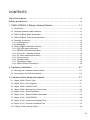
CONTENTS
About this manual - - - - - - - - - - - - - - - - - - - - - - - - - - - - - - - - - - - - - - - - iii
Safety precautions - - - - - - - - - - - - - - - - - - - - - - - - - - - - - - - - - - - - - - - - vi
1 SGDV-OCB01A CANopen Network Module - - - - - - - - - - - - - - - - - - - 1-1
1.1 Introduction - - - - - - - - - - - - - - - - - - - - - - - - - - - - - - - - - - - - - - - - - - - - - - - - - - - - - 1-1
1.2 CANopen network module features - - - - - - - - - - - - - - - - - - - - - - - - - - - - - - - - - - - - 1-1
1.3 SGDV-OCB01A Model designation- - - - - - - - - - - - - - - - - - - - - - - - - - - - - - - - - - - - - 1-2
1.4 SGDV-OCB01A Technical specifications - - - - - - - - - - - - - - - - - - - - - - - - - - - - - - - - - 1-3
1.5 Checking on delivery - - - - - - - - - - - - - - - - - - - - - - - - - - - - - - - - - - - - - - - - - - - - - - - 1-4
1.5.1 Checking items - - - - - - - - - - - - - - - - - - - - - - - - - - - - - - - - - - - - - - - - - - - - - - - - 1-4
1.5.2 Nameplate - - - - - - - - - - - - - - - - - - - - - - - - - - - - - - - - - - - - - - - - - - - - - - - - - - - 1-4
1.6 SGDV-OCB01A Hardware interface - - - - - - - - - - - - - - - - - - - - - - - - - - - - - - - - - - - - 1-5
1.6.1 RUN LED status description - - - - - - - - - - - - - - - - - - - - - - - - - - - - - - - - - - - - - - - 1-5
1.6.2 ERROR LED status description- - - - - - - - - - - - - - - - - - - - - - - - - - - - - - - - - - - - - 1-6
1.6.3 S1 and S2 – Address switches - - - - - - - - - - - - - - - - - - - - - - - - - - - - - - - - - - - - - 1-6
1.6.4 S3 - Baud rate selection switch - - - - - - - - - - - - - - - - - - - - - - - - - - - - - - - - - - - - - 1-7
1.6.5 CAN connector - - - - - - - - - - - - - - - - - - - - - - - - - - - - - - - - - - - - - - - - - - - - - - - - 1-7
1.6.6 CANopen cable - - - - - - - - - - - - - - - - - - - - - - - - - - - - - - - - - - - - - - - - - - - - - - - - 1-8
1.6.7 Termination resistor - - - - - - - - - - - - - - - - - - - - - - - - - - - - - - - - - - - - - - - - - - - - - 1-8
1.6.8 SGDV-OCB01A Dimensions - - - - - - - - - - - - - - - - - - - - - - - - - - - - - - - - - - - - - - - 1-8
2 Hardware installation - - - - - - - - - - - - - - - - - - - - - - - - - - - - - - - - - - - 2-1
2.1 Mounting the CANopen network module - - - - - - - - - - - - - - - - - - - - - - - - - - - - - - - - - 2-1
2.2 Connecting to the CAN bus network - - - - - - - - - - - - - - - - - - - - - - - - - - - - - - - - - - - - 2-2
3 Communication parameter objects - - - - - - - - - - - - - - - - - - - - - - - - - - 3-1
3.1 Object 1000h - Device Type - - - - - - - - - - - - - - - - - - - - - - - - - - - - - - - - - - - - - - - - - - 3-1
3.2 Object 1001h - Error Register - - - - - - - - - - - - - - - - - - - - - - - - - - - - - - - - - - - - - - - - 3-1
3.3 Object 1005h - COB-ID SYNC - - - - - - - - - - - - - - - - - - - - - - - - - - - - - - - - - - - - - - - - 3-1
3.4 Object 1008h - Manufacturer Device Name - - - - - - - - - - - - - - - - - - - - - - - - - - - - - - - 3-2
3.5 Object 1010h - Store Parameters - - - - - - - - - - - - - - - - - - - - - - - - - - - - - - - - - - - - - - 3-2
3.6 Object 1011h - Restore Default Parameters- - - - - - - - - - - - - - - - - - - - - - - - - - - - - - - 3-3
3.7 Object 1014h - COB-ID EMCY - - - - - - - - - - - - - - - - - - - - - - - - - - - - - - - - - - - - - - - - 3-4
3.8 Object 1016h - Consumer Heartbeat Time - - - - - - - - - - - - - - - - - - - - - - - - - - - - - - - 3-4
3.9 Object 1017h - Producer Heartbeat Time - - - - - - - - - - - - - - - - - - - - - - - - - - - - - - - - 3-5
3.10 Object 1018h - Identity Object - - - - - - - - - - - - - - - - - - - - - - - - - - - - - - - - - - - - - - - 3-6
xiiixiii
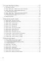
4 Process Data Objects (PDOs) - - - - - - - - - - - - - - - - - - - - - - - - - - - - - 4-1
4.1 PDO objects overview - - - - - - - - - - - - - - - - - - - - - - - - - - - - - - - - - - - - - - - - - - - - - - 4-1
4.2 Object 1400h-1403h - RPDO Communication Parameter - - - - - - - - - - - - - - - - - - - - - 4-1
4.3 Object 1600h-1603h - RPDO Mapping Parameter - - - - - - - - - - - - - - - - - - - - - - - - - - 4-3
4.3.1 Default values for RPDO - - - - - - - - - - - - - - - - - - - - - - - - - - - - - - - - - - - - - - - - - 4-4
4.4 Object 1800h-1803h - TPDO Communication Parameter - - - - - - - - - - - - - - - - - - - - - 4-6
4.5 Object 1A00h-1A03h - TPDO Mapping Parameter - - - - - - - - - - - - - - - - - - - - - - - - - - 4-8
4.5.1 Default values for TPDO- - - - - - - - - - - - - - - - - - - - - - - - - - - - - - - - - - - - - - - - - - 4-9
4.6 Mapping procedure - - - - - - - - - - - - - - - - - - - - - - - - - - - - - - - - - - - - - - - - - - - - - - - 4-11
5 Manufacturer specific objects - - - - - - - - - - - - - - - - - - - - - - - - - - - - - - 5-1
5.1 Object 2004h - Utility servo function - - - - - - - - - - - - - - - - - - - - - - - - - - - - - - - - - - - - 5-1
5.2 Object 203fh - Manufacturer error code - - - - - - - - - - - - - - - - - - - - - - - - - - - - - - - - - 5-1
5.3 Object 2100h - Get Parameter - - - - - - - - - - - - - - - - - - - - - - - - - - - - - - - - - - - - - - - - 5-2
5.4 Object 2101h - Set Parameter - - - - - - - - - - - - - - - - - - - - - - - - - - - - - - - - - - - - - - - - 5-2
5.5 Object 2211h - Read Monitor - - - - - - - - - - - - - - - - - - - - - - - - - - - - - - - - - - - - - - - - - 5-3
5.6 Object 2300h - User unit group enable - - - - - - - - - - - - - - - - - - - - - - - - - - - - - - - - - - 5-3
5.7 Object 2301h - Position User Unit - - - - - - - - - - - - - - - - - - - - - - - - - - - - - - - - - - - - - 5-3
5.8 Object 2302h - Velocity User Unit- - - - - - - - - - - - - - - - - - - - - - - - - - - - - - - - - - - - - - 5-4
5.9 Object 2303h - Acceleration User Unit - - - - - - - - - - - - - - - - - - - - - - - - - - - - - - - - - - 5-4
5.10 Object 2400h - Position Range Limit Designation- - - - - - - - - - - - - - - - - - - - - - - - - - 5-8
5.11 Object 2401h - Target_Position_In_Range- - - - - - - - - - - - - - - - - - - - - - - - - - - - - - - 5-8
5.12 Object 2402h - Actual_Position_In_Range - - - - - - - - - - - - - - - - - - - - - - - - - - - - - - 5-8
6 Device control objects - - - - - - - - - - - - - - - - - - - - - - - - - - - - - - - - - - - 6-1
6.1 SGDV-OCB01A Device control - General - - - - - - - - - - - - - - - - - - - - - - - - - - - - - - - 6.1.1 CAN network management (NMT)- - - - - - - - - - - - - - - - - - - - - - - - - - - - - - - - - - 6.1.2 Controlling the Power Drive System (PDS)- - - - - - - - - - - - - - - - - - - - - - - - - - - - 6.1.3 Modes of operation - - - - - - - - - - - - - - - - - - - - - - - - - - - - - - - - - - - - - - - - - - - - -
6-1
6-1
6-2
6-4
6.2 Object 603fh – Error code - - - - - - - - - - - - - - - - - - - - - - - - - - - - - - - - - - - - - - - - - - - 6-4
6.3 Object 6040h – Control Word- - - - - - - - - - - - - - - - - - - - - - - - - - - - - - - - - - - - - - - - - 6-4
6.4 Object 6041h – Status Word - - - - - - - - - - - - - - - - - - - - - - - - - - - - - - - - - - - - - - - - - 6-5
6.5 Object 605Ah - Quick stop option code - - - - - - - - - - - - - - - - - - - - - - - - - - - - - - - - - - 6-7
6.6 Object 6060h - Modes of Operation - - - - - - - - - - - - - - - - - - - - - - - - - - - - - - - - - - - - 6-8
6.7 Object 6061h - Modes of Operation Display - - - - - - - - - - - - - - - - - - - - - - - - - - - - - - 6-8
xivxiv
7 Pole detection mode - - - - - - - - - - - - - - - - - - - - - - - - - - - - - - - - - - - - 7-1
7.1 Introduction - - - - - - - - - - - - - - - - - - - - - - - - - - - - - - - - - - - - - - - - - - - - - - - - - - - - - 7-1
7.2 Mode of operation (6060h)- - - - - - - - - - - - - - - - - - - - - - - - - - - - - - - - - - - - - - - - - - - 7-1
7.3 Control word (6040h) - - - - - - - - - - - - - - - - - - - - - - - - - - - - - - - - - - - - - - - - - - - - - - 7-1
7.4 Status word (6041h) - - - - - - - - - - - - - - - - - - - - - - - - - - - - - - - - - - - - - - - - - - - - - - - 7-1
7.5 Pole detection condition - - - - - - - - - - - - - - - - - - - - - - - - - - - - - - - - - - - - - - - - - - - - 7-2
8 Profile position objects - - - - - - - - - - - - - - - - - - - - - - - - - - - - - - - - - - 8-1
8.1 Mode specific control word - - - - - - - - - - - - - - - - - - - - - - - - - - - - - - - - - - - - - - - - - - 8-1
8.2 Mode specific status word - - - - - - - - - - - - - - - - - - - - - - - - - - - - - - - - - - - - - - - - - - - 8-1
8.3 Object 6067h - Position Window- - - - - - - - - - - - - - - - - - - - - - - - - - - - - - - - - - - - - - - 8-2
8.4 Object 6068h - Position Window Time- - - - - - - - - - - - - - - - - - - - - - - - - - - - - - - - - - - 8-2
8.5 Object 607Fh - Maximum Profile Velocity - - - - - - - - - - - - - - - - - - - - - - - - - - - - - - - - 8-3
8.6 Object 6081h - Profile Velocity - - - - - - - - - - - - - - - - - - - - - - - - - - - - - - - - - - - - - - - - 8-3
8.7 Object 6083h - Profile Acceleration- - - - - - - - - - - - - - - - - - - - - - - - - - - - - - - - - - - - - 8-3
8.8 Object 6084h - Profile Deceleration - - - - - - - - - - - - - - - - - - - - - - - - - - - - - - - - - - - - 8-3
8.9 Object 6085h - Quick Stop Deceleration - - - - - - - - - - - - - - - - - - - - - - - - - - - - - - - - - 8-4
8.10 Object 607Ah - Target Position - - - - - - - - - - - - - - - - - - - - - - - - - - - - - - - - - - - - - - - 8-4
8.11 Object 6062h – Position Demand Value in User Units - - - - - - - - - - - - - - - - - - - - - - - 8-4
8.12 Object 6063h – Position Actual Value - - - - - - - - - - - - - - - - - - - - - - - - - - - - - - - - - - 8-5
8.13 Object 6064h – Position Actual Value in User Units - - - - - - - - - - - - - - - - - - - - - - - - 8-5
9 Homing mode objects - - - - - - - - - - - - - - - - - - - - - - - - - - - - - - - - - - - 9-1
9.1 Mode specific control word - - - - - - - - - - - - - - - - - - - - - - - - - - - - - - - - - - - - - - - - - - 9-1
9.2 Mode specific status word - - - - - - - - - - - - - - - - - - - - - - - - - - - - - - - - - - - - - - - - - - - 9-1
9.3 Object 607Ch – Home Offset - - - - - - - - - - - - - - - - - - - - - - - - - - - - - - - - - - - - - - - - - 9-2
9.4 Object 6098h - Homing Method - - - - - - - - - - - - - - - - - - - - - - - - - - - - - - - - - - - - - - - 9-2
9.5 Object 6099h - Homing Speed - - - - - - - - - - - - - - - - - - - - - - - - - - - - - - - - - - - - - - - - 9-9
9.6 Object 609Ah - Homing Acceleration - - - - - - - - - - - - - - - - - - - - - - - - - - - - - - - - - - - 9-9
xvxv
10 Profile velocity mode objects - - - - - - - - - - - - - - - - - - - - - - - - - - - - 10-1
10.1 Mode specific control word - - - - - - - - - - - - - - - - - - - - - - - - - - - - - - - - - - - - - - - - 10-1
10.2 Mode specific status word - - - - - - - - - - - - - - - - - - - - - - - - - - - - - - - - - - - - - - - - - 10-1
10.3 Object 606Bh - Velocity Demand Value - - - - - - - - - - - - - - - - - - - - - - - - - - - - - - - - 10-1
10.4 Object 606Ch - Velocity Actual Value - - - - - - - - - - - - - - - - - - - - - - - - - - - - - - - - - 10-2
10.5 Object 60FFh - Target Velocity - - - - - - - - - - - - - - - - - - - - - - - - - - - - - - - - - - - - - - 10-2
10.6 Object 6083h - Profile Acceleration- - - - - - - - - - - - - - - - - - - - - - - - - - - - - - - - - - - 10-2
10.7 Object 6084h - Profile Deceleration - - - - - - - - - - - - - - - - - - - - - - - - - - - - - - - - - - 10-3
10.8 Object 6085h - Quick Stop Deceleration - - - - - - - - - - - - - - - - - - - - - - - - - - - - - - - 10-3
11 Profile torque mode objects - - - - - - - - - - - - - - - - - - - - - - - - - - - - - 11-1
11.1 Mode specific control word- - - - - - - - - - - - - - - - - - - - - - - - - - - - - - - - - - - - - - - - - 11-1
11.2 Mode specific status word - - - - - - - - - - - - - - - - - - - - - - - - - - - - - - - - - - - - - - - - - 11-1
11.3 Object 6071h - Target Torque - - - - - - - - - - - - - - - - - - - - - - - - - - - - - - - - - - - - - - - 11-1
11.4 Object 6072h - Maximum Torque - - - - - - - - - - - - - - - - - - - - - - - - - - - - - - - - - - - - 11-2
11.5 Object 6074h - Torque Demand - - - - - - - - - - - - - - - - - - - - - - - - - - - - - - - - - - - - - 11-2
11.6 Object 6077h - Torque Actual Value - - - - - - - - - - - - - - - - - - - - - - - - - - - - - - - - - - 11-2
11.7 Object 6087h - Torque Slope - - - - - - - - - - - - - - - - - - - - - - - - - - - - - - - - - - - - - - - 11-2
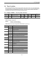
12 Touch probe - - - - - - - - - - - - - - - - - - - - - - - - - - - - - - - - - - - - - - - - 12-1
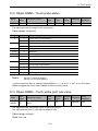
12.1 Object 60B8h - Touch probe function - - - - - - - - - - - - - - - - - - - - - - - - - - - - - - - - - 12-1
12.2 Object 60B9h - Touch probe status - - - - - - - - - - - - - - - - - - - - - - - - - - - - - - - - - - - 12-2
12.3 Object 60BAh - Touch probe pos1 pos value - - - - - - - - - - - - - - - - - - - - - - - - - - - - 12-2
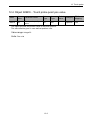
12.4 Object 60BCh - Touch probe pos2 pos value - - - - - - - - - - - - - - - - - - - - - - - - - - - - 12-3
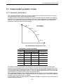
13 Interpolated position mode - - - - - - - - - - - - - - - - - - - - - - - - - - - - - - 13-1
13.1 General information - - - - - - - - - - - - - - - - - - - - - - - - - - - - - - - - - - - - - - - - - - - - - 13-1
13.2 Mode specific control word - - - - - - - - - - - - - - - - - - - - - - - - - - - - - - - - - - - - - - - - 13-3
13.3 Mode specific status word - - - - - - - - - - - - - - - - - - - - - - - - - - - - - - - - - - - - - - - - - 13-3
13.4 Object 60C1h - Interpolation Data Record - - - - - - - - - - - - - - - - - - - - - - - - - - - - - - 13-3
13.5 Object 60C2h - Interpolation Time Period - - - - - - - - - - - - - - - - - - - - - - - - - - - - - - 13-4
13.6 Guidelines for interpolated motion execution - - - - - - - - - - - - - - - - - - - - - - - - - - - - 13-4
13.6.1 Working in continuous execution: - - - - - - - - - - - - - - - - - - - - - - - - - - - - - - - - - 13-4
14 Inputs and outputs objects - - - - - - - - - - - - - - - - - - - - - - - - - - - - - - 14-1
14.1 Object 60FDh - Digital Inputs - - - - - - - - - - - - - - - - - - - - - - - - - - - - - - - - - - - - - - - 14-1
14.2 Object 60FEh - Digital Output- - - - - - - - - - - - - - - - - - - - - - - - - - - - - - - - - - - - - - - 14-1
xvixvi
15 Error handling- - - - - - - - - - - - - - - - - - - - - - - - - - - - - - - - - - - - - - - 15-1
15.1 General - - - - - - - - - - - - - - - - - - - - - - - - - - - - - - - - - - - - - - - - - - - - - - - - - - - - - - 15-1
15.2 Classes - - - - - - - - - - - - - - - - - - - - - - - - - - - - - - - - - - - - - - - - - - - - - - - - - - - - - - 15-1
15.3 EMCY message format - - - - - - - - - - - - - - - - - - - - - - - - - - - - - - - - - - - - - - - - - - - 15-1
15.4 Generic error - - - - - - - - - - - - - - - - - - - - - - - - - - - - - - - - - - - - - - - - - - - - - - - - - - 15-2
15.5 CANopen communication errors - - - - - - - - - - - - - - - - - - - - - - - - - - - - - - - - - - - - - 15-2
15.6 Emergency message- - - - - - - - - - - - - - - - - - - - - - - - - - - - - - - - - - - - - - - - - - - - - 15-3
15.7 Error code chart - - - - - - - - - - - - - - - - - - - - - - - - - - - - - - - - - - - - - - - - - - - - - - - - 15-4
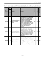
15.7.1 Error code chart 1: Errors detected by the CANopen network card - - - - - - - - - - 15-6
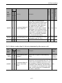
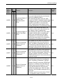
15.7.2 Error code chart 2: Errors detected by the servo unit - - - - - - - - - - - - - - - - - - - - 15-7
15.7.3 Abort SDO Transfer Protocol- - - - - - - - - - - - - - - - - - - - - - - - - - - - - - - - - - - - - 15-9
15.7.4 Recovery procedure after the interlock circuit is open: - - - - - - - - - - - - - - - - - - 15-10
16 Examples- - - - - - - - - - - - - - - - - - - - - - - - - - - - - - - - - - - - - - - - - - 16-1
16.1 Homing example - - - - - - - - - - - - - - - - - - - - - - - - - - - - - - - - - - - - - - - - - - - - - - - - 16-1
16.2 Profile position example- - - - - - - - - - - - - - - - - - - - - - - - - - - - - - - - - - - - - - - - - - - 16-2
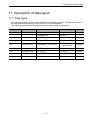
17 Description of data types - - - - - - - - - - - - - - - - - - - - - - - - - - - - - - - 17-1
17.1 Data types - - - - - - - - - - - - - - - - - - - - - - - - - - - - - - - - - - - - - - - - - - - - - - - - - - - - 17-1
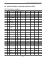
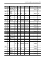
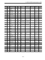
18 SGDV-OCB01A objects based on EDS- - - - - - - - - - - - - - - - - - - - - 18-1
18.1 Description of objects - - - - - - - - - - - - - - - - - - - - - - - - - - - - - - - - - - - - - - - - - - - - 18-1
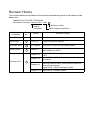
Revision History 1
xviixvii
xviiixviii
1 SGDV-OCB01A CANopen Network Module
1 SGDV-OCB01A CANopen Network Module
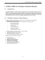
1.1 Introduction
The SGDV-OCB01A is an add-on board, compatible with -V Series models, which provides an
interface for CANopen networking (Network type). The CANopen interface enables the user to
achieve high-speed distributed control with a high level of reliability. CANopen is a higher-layer
protocol commonly used in automation industry. The specification of this protocol is maintained
and developed by the CiA (CAN in Automation) organization (www.can-cia.org).
1.2 CANopen network module features
CANopen network module offers a wide range of functions based on the following:
CANopen DS-301 specification
Drive profiles according to DSP-402, V2.0 support the following modes:
•
Pole Detection Mode
•
Profile Position Mode
•
Homing Mode
•
Profile Velocity Mode
•
Profile Torque Mode
•
Interpolated position mode
Rotary switches for setting node ID – up to 127 nodes
Communication rate of up to 1 Mbps
Standard 9-pin D-type connector
Two indicator LEDs according to CiA303-3
CANopen network module is conform to:
CiA Specifications
Safety Standard UL508
Material Compliance UL94V-0
RoHS Directive 2002/95/EC
WEEE Directive 2002/96/EC
Low Voltage Directive 73/23/EEC
EMC Directive 89/336/EEC
1-1
1 SGDV-OCB01A CANopen Network Module
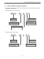
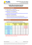
1.3 SGDV-OCB01A Model designation
The network module that is mounted onto the servopack consists of the network card and the
housing for the network card.
Model designation for the network card
SGDV - OC B 01 A
Product Series
Design revision order
Sigma-5 Series
A.........
PCB Category
Option card specification
OC: Command Option Card
01: CANopen
Responsible Branch for Product
A: Japan
B: Europe
Model designation for the housing
SGDV - OZ A 01 A
Series
Design revision order
Sigma-5 Series
A.........
Type of Option
Option case specification
Case for option module
General purpose
1-2
1 SGDV-OCB01A CANopen Network Module
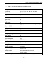
1.4 SGDV-OCB01A Technical specifications
CANopen communication standards
DS-301, V4.02
CAN bit rates
10, 20, 50, 125, 250, 500, 800, 1000 Kbps
CAN identifier
Standard 11 bit
CANopen node-ID
1-127 (set by two rotary switches)
NMT services
Slave
SDO communication
1 server
Block transfer
No
Segmented transfer
Yes
Block transfer
No
PDO communication
Supported RPDOs
Supported TPDOs
Producer and consumer, default setting according to
DSP-402
1 to 4
1 to 4
PDO mapping entries
Dynamic with maximum 2 mapping entries
SYNC
Consumer
Time stamp
No
Emergency messages
Producer
Node guarding
No
Heartbeat
Producer and Consumer
Non-volatile storage
Yes
CANopen profile for drives
DSP-402, V2.0
Axis types
Linear and Rotary
Motor type
Brushless AC servo
Storage temperature
-20 to +85 °C
Ambient temperature
0 to +55 °C
Ambient temperature to ensure
long-term reliability
+45 °C or less
Ambient humidity
90 % RH or less (non-condensing)
Vibration
4.9 m/s2 or less
Current consumption
0.28 A from 5VDC Servo Drive supply
1-3
1 SGDV-OCB01A CANopen Network Module
1.5 Checking on delivery
1.5.1 Checking items
When -V Series products such as network boards are delivered, check the items displayed in
the table below.
Check Items
Remarks
Check if the delivered products match
the ones you ordered.
Check the types marked on the nameplates of the
network unit.
Check for any visible damage.
Check the overall appearance, and check for damage
or scratches resulting from transportation.
Check if the type of SGDV is applicable
for network unit.
Check the nameplate of the SGDV.
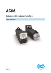
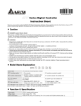
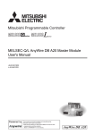
1.5.2 Nameplate
The description and production details of the product are displayed on the network module’s
nameplate as shown below.
CANopen Network Module
Model SGDV-OCB01A
xxxxxxxxxx
Serial
Number
1-4
VER:
1 SGDV-OCB01A CANopen Network Module
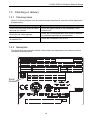
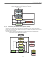
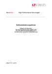
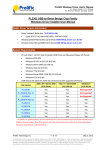
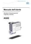
1.6 SGDV-OCB01A Hardware interface
The table below describes the elements of the SGDV-OCB01A hardware interface as displayed
in the figure on the right side of the table.
No.
Name
Description
Appearance
1
RUN LED
Indicates the status of the CANopen network
state machine.
2
ERROR LED
Indicates the status of the CAN physical layer
and indicates errors due to missing CAN
messages.
3
S1: Address
Switch
Sets the most significant bit of the CAN node
address (hexadecimal format). (See 1.6.3 S1
and S2 – Address switches.)
4
S2: Address
Switch
Sets the least significant bit of the CAN node
address (hexadecimal format). (See 1.6.3 S1
and S2 – Address switches.)
5
S3: Baud Rate
Selection Switch
Sets the baud rate using the DIP switch S3.
6
CN11 connector
D-SUB 9-Pin Plug CAN Bus Connector
7
CN12 connector
14-Pin high density Serial Port connector
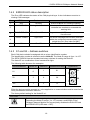
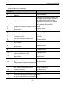
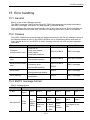
1.6.1 RUN LED status description
The RUN LED indicates the status of the CANopen Network Management (NMT) state of
machine. (For more details about the NMT see Section 6.1.1.)
Table 3 describes the RUN LED states:
No.
LED state
NMT state
Description
1
Single flash
Stopped
SGDV-OCB01A is in stopped state.
2
Blinking
Preoperational
SGDV-OCB01A is in preoperational state.
3
Light ON
Operational
SGDV-OCB01A is in operational state.
1-5
1 SGDV-OCB01A CANopen Network Module
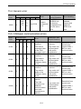
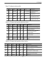
1.6.2 ERROR LED status description
The Error LED indicates the status of the CAN physical layer. It also indicates errors due to
missing CAN messages.
No.
LED State
Device state
Description
OFF
No error
SGDV-OCB01A is in working condition.
1
SINGLE FLASH
2
3
Warning Limit Reached At least one of the error counters of the CAN
controller has reached or exceeded the
warning limit.
DOUBLE FLASH
Error Control Event
A guard event (NMT) or a heartbeat event
has occurred.
TRIPLE FLASH
Sync Error
The SYNC message has not been received
within the configured communication cycle
period time out. (See index 0x1006.)
ON
Bus Off
The CAN controller bus is off.
4
5
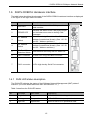
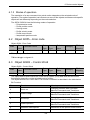
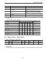
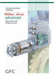
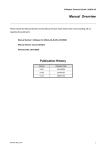
1.6.3 S1 and S2 – Address switches
Each CAN device should be assigned with a unique identification number.
The identification number is referred to as the Node-ID. The Node-ID range is from 1 to 127.
The SGDV-OCB01A has two hexadecimal rotary switches for setting the Node ID.
The Node-ID is a combination of two hexadecimal digits.
The following table shows a few examples:
Hexadecimal Value
01
0
1
01
58
3
A
3A
127
7
F
7F
Appearance
㧲㧜㧝㧞
Switch S2
㧟
㧠㧡
㧢
S1
㧣㧤 㧥
Switch S1
㧱
Decimal Address
㧱
㧠㧡
㧢
S2
㧣㧤 㧥
㧲㧜㧝㧞
㧯D
㧭㧮
㧟
㧯D
㧭㧮
Either the device must be powered on, or the application or communication must be reset for the
newly set address to become effective.
The factory default setting for the Node ID is 1.
CAUTION
Set the board address using the rotary switches before applying the power.
Exceeding the Node-ID range (1 to 127) causes a malfunction of the
CANopen Network Module and consequently disables the RUN LED and
the ERROR LED (LED state = OFF).
1-6
1 SGDV-OCB01A CANopen Network Module
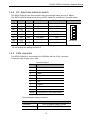
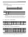
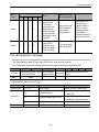
1.6.4 S3 - Baud rate selection switch
The SGDV-OCB01A can communicate using several baud rates, and up to 1Mbps.
The SGDV-OCB01A baud rate is set by the DIP switch S3 as defined in the table below.
1
Max BUS Length [m]
ON
ON
10 kbps
ON
ON
OFF
20 kbps
2500
ON
OFF
ON
50 kbps
1000
ON
OFF
OFF
125 kbps
500
OFF
ON
ON
250 kbps
250
OFF
ON
OFF
500 kbps
100
OFF
OFF
ON
800 kbps
50
OFF
OFF
OFF
1000 kbps
25
It may be necessary to use repeaters for bus lengths greater than 1000 m.
Do not change the setting of switch 4!
1.6.5 CAN connector
The SGDV-OCB01A is connected to the CAN Bus with the CN11 connector.
Connector type: D-type, 9 pin, male.
Terminal Layout
Pin No.
Name
1
NC
2
CAN-L
3
GND
4
NC
5
NC
6
NC
7
CAN-H
8
NC
9
NC
Shield
Connected to CAN cable shield
Recommended mating connector
Connector Parts
Connector
Cover
9-Pin D-SUB for cable, Female
17JE-09-H1C (DDK)
1-7
ON
4
ON
3
Baud Rate
2
3
1
2
DIP-SW: S3
1 SGDV-OCB01A CANopen Network Module
1.6.6 CANopen cable
CANopen cable has a single twisted pair with overall shielding. CANopen has a specified colour
code, and it is strongly recommended that this code is maintained.
Since CANopen networks run at high data rates, they require cable specifically designed to
carry high frequency signals. Low quality cable will attenuate the signals, and may render the
signal unreadable for the other nodes on the network.
We can only guarantee correct and reliable operation if all other equipment installed on the
CANopen network (including the network cable) has been approved by CAN in Automation (CiA).
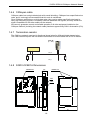
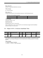
1.6.7 Termination resistor
The CAN bus network uses two bi-directional signal wires for differential data transmission.
The CAN network requires the first and the last nodes to be terminated with a 120 resistor.
Node ID
(1…127)
CAN Master
120 Ω
120 Ω
CAN_H
CAN_L
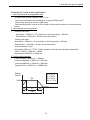
1.6.8 SGDV-OCB01A Dimensions
(24)
CONNECTOR
(12)
NAMEPLATE
CN11
(84)
(160)
(22)
CN12
20
1-8
97
2 Hardware installation
2 Hardware installation
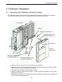
2.1 Mounting the CANopen network module
The CANopen network module will be mounted on the right side of the Sigma-V servopack.
To mount the network module to the servopack follow the instructions below.
Σ-V Amplifier
Spacer
CANopen network card
Mounting screw 3 for
network card M3 x 12
Nameplate
Cover for
network card
Metal bar
Mounting screws 1 and 2
for metal bar M3 x 6
Mounting screws 1and 2
for option card M3 x 6
1. Remove the cover from CN10 on the SGDV servo amplifier.
2. Mount the metal bar which is delivered with the network module to the SGDV amplifier
with the screws 1 and 2 at both ends of the bar.
3. Now plug in the CANopen network card to CN10.
4. Attach the network card with the screws 1, 2 and 3 to the servo amplifier, do not forget
the spacer for screw 3.
5. Now snap on the cover for the network module to the servo amplifier, the completed unit
will look like the following picture.
2-1
2 Hardware installation
2.2 Connecting to the CAN bus network
Connect the CAN cable to CN6 connector. (See Section 1.6.5 CAN connector for the connector
layout.)
2-2
3 Communication parameter objects
3 Communication parameter objects
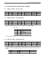
3.1 Object 1000h - Device Type
Index
Sub
Index
Parameter
Name
Data
Type
Access
Type
Default Value
Category
PDO
Mapping
1000h
0h
Device Type
u32
RO
0x00420192
Mandatory
No
Default Value
Category
PDO
Mapping
Mandatory
optional
3.2 Object 1001h - Error Register
Index
Sub
Index
Parameter
Name
Data
Type
Access
Type
1001h
0h
Error register
u8
RO
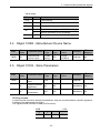
The object shell provides error information. It is part of the emergency object.
Value range
Bit
Value
Function
0
0
No error
1
Generic error
1-7
Reserved (not supported)
The error message and the error code are triggered by an EMCY object.
3.3 Object 1005h - COB-ID SYNC
Index
Sub
Index
Parameter
Name
Data
Type
Access
Type
1005h
0h
COB-ID-SYNC
u32
RW
Default Value
Category
PDO
Mapping
Mandatory
No
This object indicates the configured COB-ID frame message for the synchronization object and
whatever this device will generate through synchronization. The structure of the object is as
follows:
31
30
29
28
11
X
SYNC generate
0b
000 000 000 000 00b
3-1
10
11bit CAN-ID
1
3 Communication parameter objects
Value range
Bit
Value
Function
0-10
11bit CAN-ID
11-28
29bit CAN-ID (extended)
29
30
0
Always 0
0
Device does not generate SYNC message
1
Device generates SYNC message
31
Not for use
3.4 Object 1008h - Manufacturer Device Name
Index
Sub
Index
Parameter Name
Data
Type
Access
Type
Default
Value
Category
PDO
Mapping
1008h
0h
Manufacturer
device name
Visible
string
RO
SGDVOCB01A
Optional
No
Default
Value
Category
PDO
Mapping
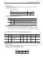
3.5 Object 1010h - Store Parameters
Index
Sub
Index
Parameter Name
Data
Type
Store parameter
field
u32
0h
Largest subindex
supported
u8
RO
Mandatory
No
1h
Save all
Parameters
u32
RW
Mandatory
No
1010h
Access
Type
Optional
Writing access
In order to avoid erroneous storage of parameters, they are only stored when a specific signature
is written to the appropriate sub-index.
The signature that is written is save (ASCII values).
MSB
LSB
e
v
a
s
65h
76h
61h
73h
3-2
3 Communication parameter objects
Reading access
On reading the appropriate sub-index, CANopen provides information about the storage
functionality in the following format:
Storage functionality
LSB
MSB
31
1
0
Auto
Cmd
2
00 0000 0000 0000 0000 0000 0000 0000
Reading Message interpretation
Bit
0
1
Value
Function
0
CANopen device does not save parameters on command.
1
CANopen device saves parameters on command.
0
CANopen device does not save parameters autonomously.
1
CANopen device saves parameters autonomously.
On receipt of a correct save signature to the appropriate sub-index, CANopen stores the
parameters to the device and the device generates an SDO for confirmation.
• If the storage process fails, CANopen responds with SDO abort code 06060000h.
• If an incorrect signature is sent, CANopen responds with SDO abort code 08000020h.
3.6 Object 1011h - Restore Default Parameters
Index
Sub
Index
Parameter Name
Data
Type
Restore Default
Parameter
u32
0h
Largest subindex
supported
u8
1h
Restore all Parameters u32
1011h
Access
Type
Default
Value
Category
PDO
Mapping
Optional
RO
Mandatory
No
RW
Mandatory
No
Writing access
In order to avoid erroneous storage of parameters, they are only stored when a specific
signature is written to the appropriate sub-index.
The signature that is written is load (ASCII values):
MSB
LSB
d
a
o
l
64h
61h
6Fh
6Ch
3-3
3 Communication parameter objects
Reading access
When the appropriate sub-index is read, CANopen provides information about the storage
functionality in the following format:
Storage Functionality
LSB
MSB
31
2
00 0000 0000 0000 0000 0000 0000 0000
1
0
Auto
Cmd
Meaning
Bit
0
Value
Function
0
CANopen device does not restore default parameters on command.
1
CANopen device restores default parameters on command.
• When a correct load signature is received by the appropriate sub-index, CANopen
restores the default parameters to the device, and the device generates an SDO for
confirmation.
• If the restoration fails, CANopen responds with an SDO abort code 06060000h.
• If an incorrect signature is sent, CANopen responds with an SDO abort code 08000020h.
• The default values are set as valid after the device has been reset or power cycled.
3.7 Object 1014h - COB-ID EMCY
Index
Sub
Index
Parameter Name
Data
Type
Access
Type
Default Value
Category
PDO
Mapping
1014h
0h
COB-ID EMCY
message
u32
RO
0x80h+Node ID
Mandatory
No
This object indicates the configured COB-ID frame message of the emergency object and
whatever EMCY exists in the device.
3.8 Object 1016h - Consumer Heartbeat Time
Index
Sub
Index
Parameter Name
Data
Type
Access
Type
Consumer heartbeat time
1016h
0h
Number of Entries
u8
1h
Consumer 1 heartbeat time u32
Default
Value
Category
PDO
Mapping
Optional
No
RO
Mandatory
RW
Optional
This object indicates the expected consumer heartbeat cycle time. The consumer heartbeat
value must be higher than the producer cycle time (Object 1017h), otherwise the consumer will
perceive it as communication lost. Monitoring this heartbeat will start after the reception of the
first heartbeat. Until it is received, the state of the heartbeat producer is unknown.
3-4
3 Communication parameter objects
Sub-index 0h
Number of supported heartbeat consumers.
Value range:
1h = One consumer.
Sub-index 1h
Contains the definitions for the heartbeat consumer in the following structure:
Structure of the heartbeat consumer
31
24
Reserved
23
16
Consumer node-ID
15
0
Heartbeat time
Value range:
Consumer node-ID: 1-127.
Heartbeat time:
Requested time cycle in 1 msec units.
If the heartbeat time is zero or the node-ID is out of the above range, then the heartbeat
consumer object will not be active.
3.9 Object 1017h - Producer Heartbeat Time
Index
Sub
Index
Parameter Name
Data
Type
Access
Type
Default Value
Category
PDO
Mapping
1017h
0h
Producer Heartbeat
time
U16
RW
0x0
Mandatory
No
This object defines the Heartbeat cycle time.
The Heartbeat is a cyclic signal that a CAN device sends to the network. The Heartbeat consumer
receives this cyclic signal message and it can indicate that the heartbeat producer is working
properly.
Value range:
0 = Disable Producer Heartbeat.
1...65535 (1…FFFFh) = Cycle time [msec].
3-5
3 Communication parameter objects
3.10 Object 1018h - Identity Object
Index
Sub
Index
Parameter Name
Data
Type
Access
Type
Default Value
Identity Object
1018h
Category
PDO
Mapping
Mandatory
0h
Number of Entries
u8
RO
1h
Vendor ID
u32
2h
Product Code
3h
4h
0x4
Mandatory
No
RO
Mandatory
No
u32
RO
Optional
No
Revision Number
u32
RO
Optional
No
Serial Number
u32
RO
Optional
No
This object provides general identification information for the CANopen device.
3-6
4 Process Data Objects (PDOs)
4 Process Data Objects (PDOs)
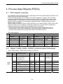
4.1 PDO objects overview
The CANopen protocol allows the user to map objects into Process Data Objects (PDOs) to use
these PDOs for real time data transfer.
A PDO message length is up to 8 bytes and an SDO message is 16 bytes. Since the data
contained in several SDOs can be configured into one PDO, using PDOs can reduce each
message length. This reduces the amount of data transferred, making communication more
efficient. PDOs use different Communication Object Identifiers (COB-ID) which give them
higher priority over SDOs.
SGDV-OCB01A supports 4 Receive PDOs (RPDO) and 4 Transmit PDOs (TPDO). Each PDO
uses two objects, one for mapping configuration and one for communication configuration.
Mapping configuration defines which objects this PDO will include.
Communication configuration defines the PDO communication parameters such as:
communication object, PDO active/disable, generating trigger, inhibit time and more.
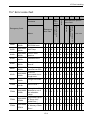
The table below describes the objects that relate to the relevant PDOs:
PDO related objects
Receive PDO
#
Transmit PDO
COB-ID
Communication object
Mapping
object
COB-ID
Communication object
Mapping
object
1
200h+Node-IDh
1400h
1600h
180h+Node-IDh
1800h
1a00h
2
300h+Node-IDh
1401h
1601h
280h+Node-IDh
1801h
1a01h
3
400h+Node-IDh
1402h
1602h
380h+Node-IDh
1802h
1a02h
4
500h+Node-IDh
1403h
1603h
480h+Node-IDh
1803h
1a03h
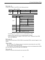
4.2 Object 1400h-1403h - RPDO Communication Parameter
Object 1400h-1403h – RPDO Communication Parameter
Index
Sub
Index
Parameter Name
Data
Type
Access
Type
Default
Value
Receive PDO
Communication
Parameter 1-4
1400h1403h
Category
PDO
Mapping
Mandatory
0h
Number of Entries
u8
RO
1h
COB-ID
u32
2h
Transmission Type
3h
Mandatory
No
RW
Mandatory
No
u8
RW
Mandatory
No
Inhibit Time
u16
RW
Optional
No
4h
Compatibility Entry
u8
RO
Optional
No
5h
Event Timer
u16
RW
Optional
No
4-1
0x5
4 Process Data Objects (PDOs)
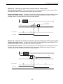
Sub-index 1h
Contains the COB-ID of the RPDO in the following structure:
Structure of COB-ID of RPDO
31
30
29
Valid
1
0
Bit
Value
28
11
10
000 000 000 000 00b
1
11bit CAN-ID
29bit CAN-ID
Function
11bit CAN-ID according to the object
0-10
11-28
Object Number
Default Value
1400h
200h+Node ID
1401h
300h+Node ID
1402h
400h+Node ID
1403h
500h+Node ID
29bit CAN-ID (extended)
29
0
Always 0
30
1
Always 1
0
PDO enable/valid
1
PDO disable/is not valid
31
• The validity bit (bit 31) allows the user to enable/disable the PDO.
• While the PDO is valid (bit 31=0), no other bits can be changed.
• In the event that bit 29 is changed or 29bit CAN-ID is sent, CANopen will send SDO
abort code 06090030h.
Sub-index 2h
Defines the transmission type. SGDV-OCB01A can generate PDOs using time triggers or event
triggers.
Value range:
00h = time driven. The CANopen device will actuate the received data at the next SYNC.
The time interval is set to sub-index 03h.
FFh = event driven. PDO can be generated at any time by control word changing (object 6040h).
Any other data will generate SDO abort code 06090030h.
Sub-index 3h
Inhibit time. Defines the time interval for the time-driven PDO.
4-2
4 Process Data Objects (PDOs)
Value range:
0 = disable inhibit time.
0…65535 (1…FFFFh) = time interval in 0,1 msec
While the PDO is valid (bit 31=0 in sub-index 1h) the value can not be changed.
Sub-index 4h
Compatibility entry – reserved.
Any read or write access will generate SDO abort code 06090011h.
Sub-index 5h
Event-timer. Defines the minimum time interval between 2 event-driven PDOs.
Value range:
0 = disable event timer.
0…65535 (1…FFFFh) = time interval in 1msec
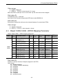
4.3 Object 1600h-1603h - RPDO Mapping Parameter
Object 1600h-1603h – RPDO mapping parameter
Index
Sub
Index
Parameter Name
Data
Type
Access
Type
Receive PDO Mapping
Parameter 1-4
1600h1603h
Default
Value
Category
PDO
Mapping
Mandatory
0h
Number of Entries
u8
RW
See Table Mandatory
No
1h
Mapping Entry 1
u32
RW
See Table Mandatory
No
2h
Mapping Entry 2
u32
RW
See Table Optional
No
3h
Mapping Entry 3
u32
RW
See Table Optional
No
4h
Mapping Entry 4
u32
RW
See Table Optional
No
5h
Mapping Entry 5
u32
RW
See Table Optional
No
6h
Mapping Entry 6
u32
RW
See Table Optional
No
7h
Mapping Entry 7
u32
RW
See Table Optional
No
8h
Mapping Entry 8
u32
RW
See Table Optional
No
Sub-index 0h
Number of entries. Number of objects mapped in the PDO.
Value range:
0h = disable mapping.
1h = 1 object (at least, mandatory)
2h = 2 objects.
3h = 3 objects.
4h = 4 objects.
5h = 5 objects.
6h = 6 objects.
7h = 7 objects.
8h = 8 objects (max).
4-3
4 Process Data Objects (PDOs)
Sub-index 1h to 8h
Application object.
Value range:
31
16
Object Index
15
8
Sub-Index
7
0
Length
The length is the number of bits in hex format. (For example - Length of Object with data type
u32 is 20h; length of object with data type i16 is 10h)
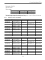
4.3.1 Default values for RPDO
Object 1600h - RPDO 1 Mapping
Value
Description
Function
Sub-index 0h
Number of objects
1
Sub-index 1h
Mapping 1st object
60400010h
Object 6040h,
sub-index 0, u16
Control Word
Sub-index 2h
Mapping 2nd object
-
-
Sub-index 3h
Mapping 3rd object
-
-
Sub-index 4h
Mapping 4th object
-
-
Sub-index 5h
Mapping 5th object
-
-
Sub-index 6h
Mapping 6th object
-
-
Sub-index 7h
Mapping 7th object
-
-
Sub-index 0h
Number of objects
1
Object 1601h - RPDO 2 Mapping
Value
Description
Function
Sub-index 0h
Number of objects
2
Sub-index 1h
Mapping 1st object
60400010h
Object 6040h
sub-index 0, u16
Control Word
Sub-index 2h
Mapping 2nd object
607a0020h
Object 607ah
sub-index 0, i32
Target Position
Sub-index 3h
Mapping 3rd object
Sub-index 4h
Mapping 4th object
Sub-index 5h
Mapping 5th object
Sub-index 6h
Mapping 6th object
Sub-index 7h
Mapping 7th object
Sub-index 8h
Mapping 8th object
4-4
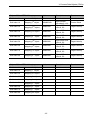
4 Process Data Objects (PDOs)
Object 1602h - RPDO 3 Mapping
Value
Description
Function
Sub-index 0h
Number of objects
2
Sub-index 1h
Mapping 1st object
60400010h
Object 6040h
sub-index 0, u16
Control Word
Sub-index 2h
Mapping 2nd object
60ff0020h
Object 60ffh subindex 0, i32
Target Velocity
Sub-index 3h
Mapping 3rd object
60ff0020h
Object 60ffh subindex 0, i32
Target Velocity
Sub-index 4h
Mapping 4th object
60ff0020h
Object 60ffh subindex 0, i32
Target Velocity
Sub-index 5h
Mapping 5th object
60ff0020h
Object 60ffh subindex 0, i32
Target Velocity
Sub-index 6h
Mapping 6th object
60ff0020h
Object 60ffh subindex 0, i32
Target Velocity
Sub-index 7h
Mapping 7th object
60ff0020h
Object 60ffh subindex 0, i32
Target Velocity
Sub-index 8h
Mapping 8th object
60ff0020h
Object 60ffh subindex 0, i32
Target Velocity
Object 1603h - RPDO 4 Mapping
Value
Description
Function
Sub-index 0h
Number of objects
0
-
-
Sub-index 1h
Mapping 1st object
-
-
-
Sub-index 2h
Mapping 2nd object
-
-
-
Sub-index 3h
Mapping 3rd object
-
-
-
Sub-index 4h
Mapping 4th object
-
-
-
Sub-index 5h
Mapping 5th object
-
-
-
Sub-index 6h
Mapping 6th object
-
-
-
Sub-index 7h
Mapping 7th object
-
-
-
Sub-index 8h
Mapping 8th object
-
-
-
4-5
4 Process Data Objects (PDOs)
4.4 Object 1800h-1803h - TPDO Communication Parameter
Object 1800h-1803h – TPDO Communication Parameter
Sub
Index
Index
Data
Type
Parameter Name
Access
Type
Default
Value
Transmit PDO
Communication
Parameter 1-4
1800h1803h
PDO
Mapping
Category
Mandatory
0h
Number of Entries
u8
RO
1h
COB-ID
u32
2h
Transmission Type
3h
0x5
Mandatory
No
RW
Mandatory
No
u8
RW
Mandatory
No
Inhibit Time
u16
RW
Optional
No
4h
Compatibility Entry
u8
RO
Optional
No
5h
Event Timer
u16
RW
Optional
No
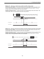
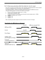
Sub-index 1h
Contains the COB-ID of the TPDO in the following structure:
Structure of COB-ID of TPDO
31
30
29
Valid
1
0
Bit
Value
28
11
10
000 000 000 000 00b
1
11bit CAN-ID
29bit CAN-ID
Function
11bit CAN-ID according to the object
0-10
11-28
Object Number
Default Value
1800h
180h+Node ID
1801h
280h+Node ID
1802h
380h+Node ID
1803h
480h+Node ID
29bit CAN-ID (extended)
29
0
Always 0
30
1
Always 1
0
PDO enable/valid
1
PDO disable/is not valid
31
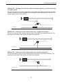
• The validity bit (bit 31) allows the user to configure PDO without having to use it.
• While the PDO is valid (bit 31=0) no other bits can be changed.
• In the event that bit 29 is changed or 29bit CAN-ID is sent, CANopen will send SDO
abort code 06090030h.
4-6
4 Process Data Objects (PDOs)
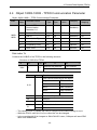
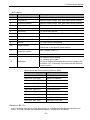
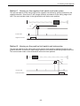
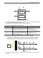
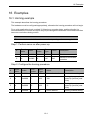
Sub-index 2h
Defines the transmission type. SGDV-OCB01A can generate PDOs using time triggers or event
triggers.
0h
Synchronous-acyclic.
1h
Synchronous-cyclic every SYNC.
2h
Synchronous-cyclic every 2nd SYNC.
3h
Synchronous-cyclic every 3rd SYNC.
4h
Synchronous-cyclic every 4th SYNC.
F0h
Synchronous-cyclic every 240th SYNC.
F1h...FBh
Reserved
FCh
RTR only (synchronous)
FDh
RTR only (event-driven)
FEh
Event-driven (manufacturer specific)
FFh
Event-driven.
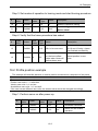
• Synchronous Acyclic - triggered by an application specific event. The message is
transmitted synchronously with the Sync object but not periodically.
• Synchronous cyclic - transmitted within the synchronous window. The number of the
transmission type (1 to 240) indicates the number of Sync objects between two PDO
transmissions.
• RTR synchronous – the device samples data at every SYNC and transmits it on request.
• RTR event-driven – the device starts sampling data on request and transmits it immediately.
• Event-driven (FE) – device transmits PDO at every change of the mapped object
• Event-driven (FF) - device transmits PDO at every change of the mapped status word or
based on the configuration of the Event Timer.
• Any other data will generate SDO abort code 06090030h.
4-7
4 Process Data Objects (PDOs)
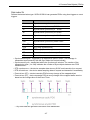
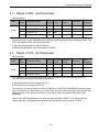
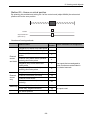
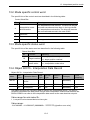
Sub-index 3h
Inhibit time. Defines the minimum time interval between 2 event-driven PDOs (if sub-index 2h =
FEh or FFh).
Value range:
0 = disable inhibit time.
0…65535 (1…FFFFh) = time interval in 0,1 msec
While the PDO is valid (bit 31=0 in sub-index 1h) the value can not be changed.
Sub-index 4h
Compatibility entry – reserved.
Any read or write access will generate SDO abort code 06090011h.
Sub-index 5h
Event-timer.
Defines the maximum time interval between 2 event-driven PDOs (if sub-index 2h = FEh or FFh).
In case sub-index 2h = FFh, sub-index 5h must have a value different from zero, otherwise the
PDO will be triggered only once.
Value range:
0 = disable event timer.
0...65535 (1...FFFFh) = time interval in 1 msec
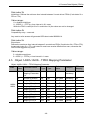
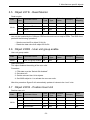
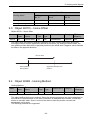
4.5 Object 1A00h-1A03h - TPDO Mapping Parameter
Object 1A00h-1A03h – TPDO Mapping Parameter
Index
Sub
Index
Parameter Name
Data
Type
Access
Type
Default
Value
Transmit PDO
Mapping Parameter
1-4
1A00h1A03h
Category
PDO
Mapping
Mandatory
0h
Number of Entries
u8
RW
See Table
Mandatory
No
1h
Mapping Entry 1
u32
RW
See Table
Mandatory
No
2h
Mapping Entry 2
u32
RW
See Table
Optional
No
3h
Mapping Entry 3
u32
RW
See Table
Optional
No
4h
Mapping Entry 4
u32
RW
See Table
Optional
No
5h
Mapping Entry 5
u32
RW
See Table
Optional
No
6h
Mapping Entry 6
u32
RW
See Table
Optional
No
7h
Mapping Entry 7
u32
RW
See Table
Optional
No
8h
Mapping Entry 8
u32
RW
See Table
Optional
No
4-8
4 Process Data Objects (PDOs)
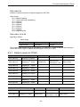
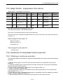
Sub-index 0h
Number of entries. Number of objects mapped in the PDO.
Value range:
0h = disable mapping.
1h = 1 object (at least, mandatory)
2h = 2 objects.
3h = 3 objects.
4h = 4 objects.
5h = 5 objects.
6h = 6 objects.
7h = 7 objects.
8h = 8 objects (max).
Sub-index 1h to 8h
Application object.
Value range:
31
16
Object Index
15
8
7
Sub-Index
0
Length
The length is the number of bits in hex format. (For example - Length of objects with data type
u32 or i32 is 20h; length of objects with data type u16 or i16 is 10h.)
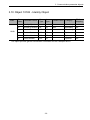
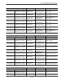
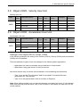
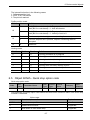
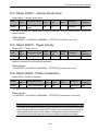
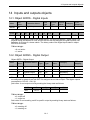
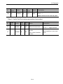
4.5.1 Default values for TPDO
Object 1A00h - TPDO 1 Mapping
Value
Description
Function
Sub-index 0h
Number of objects
1
Sub-index 1h
Mapping 1st object
60400010h
Object 6041h,
sub-index 0, u16
Status Word
Sub-index 2h
Mapping 2nd object
-
-
-
Sub-index 3h
Mapping 3rd object
-
-
-
Sub-index 4h
Mapping 4th object
-
-
-
Sub-index 5h
Mapping 5th object
-
-
-
Sub-index 6h
Mapping 6th object
-
-
-
Sub-index 7h
Mapping 7th object
-
-
-
Sub-index 8h
Mapping 8th object
-
-
-
-
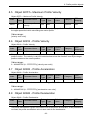
Object 1A01h - TPDO 2 Mapping
Value
Sub-index 0h
Number of objects
2
Sub-index 1h
Mapping 1st object
60400010h
4-9
Description
Function
Object 6041h
sub-index 0, u16
Status Word
4 Process Data Objects (PDOs)
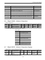
Object 1A01h - TPDO 2 Mapping
Value
Description
Function
Sub-index 2h
Mapping 2nd object
60640020h
Object 6064h
sub-index 0, i32
Actual position in
user units
Sub-index 3h
Mapping 3rd object
60640020h
Object 6064h
sub-index 0, i32
Actual position in
user units
Sub-index 4h
Mapping 4th object
60640020h
Object 6064h
sub-index 0, i32
Actual position in
user units
Sub-index 5h
Mapping 5th object
60640020h
Object 6064h
sub-index 0, i32
Actual position in
user units
Sub-index 6h
Mapping 6th object
60640020h
Object 6064h
sub-index 0, i32
Actual position in
user units
Sub-index 7h
Mapping 7th object
60640020h
Object 6064h
sub-index 0, i32
Actual position in
user units
Sub-index 8h
Mapping 8th object
60640020h
Object 6064h
sub-index 0, i32
Actual position in
user units
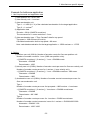
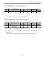
Object 1A02h - TPDO 3 Mapping
Value
Description
Function
Sub-index 0h
Number of objects
2
Sub-index 1h
Mapping 1st object
60400010h
Object 6041h
sub-index 0, u16
Status Word
Sub-index 2h
Mapping 2nd object
606c0020h
Object 606ch
sub-index 0, i32
Actual Velocity value
Sub-index 3h
Mapping 3rd object
606c0020h
Object 606ch
sub-index 0, i32
Actual Velocity value
Sub-index 4h
Mapping 4th object
606c0020h
Object 606ch
sub-index 0, i32
Actual Velocity value
Sub-index 5h
Mapping 5th object
606c0020h
Object 606ch
sub-index 0, i32
Actual Velocity value
Sub-index 6h
Mapping 6th object
606c0020h
Object 606ch
sub-index 0, i32
Actual Velocity value
Sub-index 7h
Mapping 7th object
606c0020h
Object 606ch
sub-index 0, i32
Actual Velocity value
Sub-index 8h
Mapping 8th object
606c0020h
Object 606ch
sub-index 0, i32
Actual Velocity value
Object 1A03h - TPDO 4 Mapping
Value
Description
Function
Sub-index 0h
Number of objects
0
-
-
Sub-index 1h
Mapping 1st object
-
-
-
Sub-index 2h
Mapping 2nd object
-
-
-
4-10
4 Process Data Objects (PDOs)
Object 1A03h - TPDO 4 Mapping
Value
Description
Function
Sub-index 3h
Mapping 3rd object
-
-
-
Sub-index 4h
Mapping 4th object
-
-
-
Sub-index 5h
Mapping 5th object
-
-
-
Sub-index 6h
Mapping 6th object
-
-
-
Sub-index 7h
Mapping 7th object
-
-
-
Sub-index 8h
Mapping 8th object
-
-
-
4.6 Mapping procedure
The following procedure is used for mapping, which may take place during the Pre-operational
NMT state.
The procedure is relevant to RPDO and to TPDO.
1. Remove the PDO by setting the validity bit (bit 31) to 1b in sub-index 01h of the
corresponding PDO communication object.
2. Disable mapping by setting sub-index 00h of the according mapping object to 00h.
3. Assign objects to corresponding sub-indexes (object A to sub-index 01h, object B to
sub-index 02h.)
4. Enable mapping by setting sub-index 00h of the mapping object to the number of the
mapped objects.
5. Create a PDO by setting the validity bit (bit 31) to 0b in sub-index 01h of the
corresponding PDO communication object.
• If during step 3 the CANopen device detects that the mapping object and sub index are
not existing or cannot be mapped, the device will generate SDO abort code 06020000h
or 06040041h.
• If during step 4 the CANopen device detects that the RPDO is not valid or not possible,
the device will generate SDO abort code 06020000h or 06040042h.
The following example describes the process of mapping a status word (6041h) and position
actual value (6064h) into TPDO1.
4-11
4 Process Data Objects (PDOs)
Example
The Node-ID is 7.
The TPDO1 communication object is 1800h.
The TPDO1 mapping object is 1A00h and should perform as shown in Table 49 at the end of
the procedure.
Object 1800h - TPDO 1 Mapping
Sub-index 0h
2
Sub-index 1h
6041h
Sub-index 2h
6064h
The Required CAN Messages
#
r/w
Index
Sub
Index
Data
Type
Value
Description
1
w
0x1800
1
u32
C0000187h
Disable TPDO1 for Node-ID 7 (180 +7)
Bit 31=1 (Binary)
2
w
0x1a00
0
u32
0
Destroying the number of the mapped
objects in the mapping object
3
w
0x1a00
1
u32
60410010h
Map object 6041h, sub index 0, data type
u16 (10h)
4
w
0x1a00
2
u32
60640020h
Map object 6063h, sub index 0, data type
i32 (20h)
5
w
0x1a00
0
u8
2
Declaring about 2 objects that have been
entered
6
w
0x1800
1
u32
40000187h
Enable TPDO1 for Node-ID 7 (180+7)
Bit 31=0 (Binary)
4-12
5 Manufacturer specific objects
5 Manufacturer specific objects
5.1 Object 2004h - Utility servo function
Utility servo function
Index
Sub
Index
Parameter Name
Data
Type
Access
Type
Default
Value
Category
PDO
Mapping
2004h
0h
Utility servo function
i8
RW
0
Manufacturer
specific
No
This object should be used for the SERVOPACK utility function. By setting the value with SDO,
the indicated function is started. After that, the value shows the status of the function.
Value range: Integer 8
Data description
Value
Data description
Explanation
-128 to -2
Reserved
-1
Error operation
Last function completed with error
0
No operation
(normal mode)
No effect. Completed without error.
1
Node reset
Node is reset by oneself automatically. Another way of doing
Reset by NMT message - Reset Application.
2 to 127
Reserved
No effect
Note: While executing, the value is kept in this object. When the function is completed, the
value will be set to 0 or less according to the status. During the execution the value cannot be
set to a different value.
5.2 Object 203fh - Manufacturer error code
Manufacturer error code
Index
Sub
Index
Parameter Name
Data
Type
Access
Type
Default
Value
Category
PDO
Mapping
203fh
0h
Manufacturer
error code
u32
RO
00000000h
Manufacturer
specific
Yes
This object defines the error code specified by the manufacturer.
Value range: Unsigned 32
Data description
The object consists of 4 bytes with the data as shown in the description below. Emergency error
code and fault code is referred to section 15.6 Emergency message and 15.7 Error code chart.
Byte
3
2
1
0
Error Monitor
Reserved
Attribute
Fault Code
Note: The object shows not only Sigma-V alarm codes but also Sigma-V warning codes.
5-1
5 Manufacturer specific objects
5.3 Object 2100h - Get Parameter
Get Parameter
Index
Sub
Index
Parameter Name
Data
Type
Access
Type
Default
Value
Category
PDO
Mapping
Get Parameter
2100h
0h
Number of Entries
u8
RO
1h
Parameter ID
u16
RW
2h
Parameter value
i16
RO
SGDV-OCB01A can enable the user to read the SGDV parameters via the CANopen network.
Parameters can only be handled by the CANopen SDO service and can not map to PDOs. The
SDO client performs the following operations:
1. Sets the parameter ID to object 2100h/1h.
2. Reads the parameter value from object 2100h/2h.
5.4 Object 2101h - Set Parameter
Set Parameter
Index
Sub
Index
Parameter Name
Data
Type
Access
Type
Default
Value
Category
PDO
Mapping
Set Parameter
2101h
0h
Number of Entries
u8
RO
1h
Parameter ID
u16
RW
2h
Parameter value
i16
RW
The CANopen SDO client can write each SGDV-parameter value with the object 0x2101.
The SDO client performs the following operations:
1. Sets the parameter ID to object 0x2101/1.
2. Writes the value to object 0x2101/2.
This object is only active when the SGDV-OCB01A is in SWITCH ON DISABLED machine state
(this can be done by CAN master or by sending the value 0 to the control word-object 6040h/0h).
Sending object 2101h when the machine is in another state will generate SDO abort code
8000022h.
Some of the SGDV parameters only become effective after a RESET. (For details see the
related manuals.) Changing these parameters requires the user to reset the SGDV.
5-2
5 Manufacturer specific objects
5.5 Object 2211h - Read Monitor
Read monitor
Index
Sub
Index
Parameter Name
Data
Type
Access
Type
Default
Value
Category
PDO
Mapping
Read monitor
2211h
0h
Number of Entries
u8
RO
1h
Var ID
u8
RW
2h
Var value
i32
RO
SGDV-OCB01A enables the user to read the SGDV monitor via the CANopen network. Data
can only be handled by the CANopen SDO service and can not map to PDOs. The SDO client
performs the following operations:
• Sets the monitor ID to object 2211h/1h.
• Reads the data value from object 2211h/2h.
5.6 Object 2300h - User unit group enable
User unit group enable
Index
Sub
Index
2300h
Parameter Name
Data
Type
Access
Type
Default
Value
User unit group enable
u8
RW
1
Category
PDO
Mapping
No
Data Description:
This object enables the setting of the user units.
Procedure:
1. FSA state must be “Switch ON disabled”.
2. Set value to 0.
3. Set the relevant User Units objects.
4. Set 2300h object to 1 to activate the new user units.
After this procedure Sigma-5 will automatically update all values to the “new” units.
5.7 Object 2301h - Position User Unit
Position user unit
Index
Sub
Index
Parameter Name
Data
Type
Access
Type
Default
Value
Category
PDO
Mapping
Position user unit
2301h
0h
Number of Entries
u8
RO
2
No
1h
Numerator
u32
RW
1
No
2h
Denominator
u32
RW
1
No
5-3
5 Manufacturer specific objects
5.8 Object 2302h - Velocity User Unit
Velocity user unit
Index
Sub
Index
Parameter Name
Data
Type
Access
Type
Default
Value
Category
PDO
Mapping
Velocity user unit
2302h
0h
Number of Entries
u8
RO
2
No
1h
Numerator
u32
RW
1
No
2h
Denominator
u32
RW
1
No
5.9 Object 2303h - Acceleration User Unit
Acceleration user unit
Index
Sub
Index
Parameter Name
Data
Type
Access
Type
Default
Value
Category
PDO
Mapping
Acceleration user unit
2303h
0h
Number of Entries
u8
RO
2
No
1h
Numerator
u32
RW
1
No
2h
Denominator
u32
RW
1
No
Settings of the objects 2301h, 2302h, 2303h
In the following examples the setting of the Position (2301h), Velocity (2302h) and Acceleration
(2303h) will be explained.
There are basically 2 types of user unit settings for the following basic applications:
• Applications for linear movements using a ballscrew or linear motors.
• Applications using gear boxes for rotary movement.
Also there are two ways to set the user acceleration unit considering the dimensions:
• Type 1 is to set the “Time Constant” data for top speed, for example 80 msec
acceleration for 1000 mm/sec.
• Type 2 is to set physical data, such as mm/sec2 or Deg/sec2.
Note: When setting another user unit, the ratio between numerator (sub index 1h) and denominator (sub index 2h) must be below 1000. If this condition is not fulfilled, the new user unit will
not be enabled.
5-4
5 Manufacturer specific objects
Example for ballscrew application
1. User requirements and application data
1) User position unit = 0.001 mm
2) User velocity unit = 1 mm/sec
3) User acceleration unit
Type 1: = 1/1000 (0.1 %) of the calculated acceleration for the target application.
Type 2: = 1 mm/sec2.
4) Application data
Encoder = 20 bit (1048576 counts/rev)
The movement for 1 motor revolution = 2 mm.
5) User acceleration type 1 “Time Constant” data for top speed
Top speed = 1000 mm/sec (60 m/min).
Calculated acceleration time to top speed = 80 msec.
Note: calculated acceleration for the target application = 12500 mm/sec2 = 1.275G.
2. Setting
1) Position user unit (2301h): Number of encoder counts for One user position unit
Number of encoder counts for 1 mm (1000 user position units).
= {(1048576 counts/rev) / (2 mm/rev)} * 1 mm = 524288 counts.
Numerator = 524288
Denominator = 1000
2) Velocity user unit (2302h): Number of encoder counts per msec for One user velocity unit.
Number of encoder counts per sec for 1 mm/sec (1 user velocity unit).
= {(1048576 counts/rev) / (2 mm/rev)} * 1 mm = 524288 counts/sec: 1000 msec.
Numerator = 524288
Denominator = 1000
3) Acceleration user unit (2303h): Number of encoder counts increments per msec. for
One user acceleration unit.
Type 1
Number of encoder counts per msec for top speed = 1000 mm/sec = 1mm/msec
= {(1048576 counts/rev) / (2 mm/rev)} * 1mm/msec = 524288 counts/msec.
Numerator = 524288
Denominator = 80 *1000
Type 2
Number of encoder counts per msec for 1 mm/sec = 524288 counts/msec.
Number of encoder counts increments / msec for 1 mm/sec = 524288/1000*1000.
Numerator = 524288 * 100
Denominator = 1000 *1000
5-5
5 Manufacturer specific objects
Example for rotary table application
1. User requirements and application data
Note: Deg, Rev = dimension for rotary table, deg, rev = servomotor dimension
1) User position unit = 0.001 Deg
2) User velocity unit =1 Deg/sec
3) User acceleration unit
Type 1: = 1/1000 (0.1 %) of the calculated acceleration for the target application.
Type 2: = 1 Deg/sec2.
4) Application data
Encoder = 20 bit (1048576 counts/rev)
The rotary table moves 36 Degrees for 1 motor revolution.
5) User acceleration type 2 “Time Constant” data for top speed = 10 Rev/sec
(3600 Deg/rev)
Top speed = 10 Rev/sec (3600 Deg/sec).
Calculated acceleration time to top speed = 80 msec.
Note: calculated acceleration for the target application = 45000.
2. Setting
1) Position user unit (2301h): Number of encoder counts for One user position unit
Number of encoder counts for One user position unit = 0.001 Deg.
= {(1048576 counts/rev) / (36 Deg/rev)} * 0.001 Deg = 1048576/36 counts/sec: 1000 msec.
Numerator = 1048576
Denominator = 36*1000
2) Velocity user unit (2302h): Number of encoder counts per msec for One user velocity unit
Number of encoder counts per sec for One user velocity unit = 1 Deg/sec.
= {(1048576 counts/rev) / (36 Deg/rev)} * 1 Deg/sec = 1048576/36 counts/sec: 1000 msec.
Numerator = 1048576
Denominator = 36*1000
3) Acceleration user unit (2303h): Number of encoder counts increments per msec. for
One user acceleration unit.
Type 1
Number of encoder counts per msec. for top speed = 3600 Deg/sec = 3.6 Deg/msec
= {(1048576 counts/rev) / (36 Deg/rev)} * 3.6 Deg/msec =1048576/10
Numerator = 1048576*100
Denominator = 10*80 *1000
Type 2
Number of encoder counts per msec. for 1 Deg/sec.
= {(1048576 counts/rev) / (36 Deg/rev)} /1000 msec =1048576/10/36*1000
Number of encoder counts increments per msec for 1 Deg/sec
=1048576/(36*1000*1000)
Numerator = 1048576 * 100
Denominator = 36*1000 *1000
5-6
5 Manufacturer specific objects
Example for linear motor application
1. User requirements and application data
A linear motor moves a distance AB = 1.4 m.
The motor acceleration and deceleration is equal to 5000 mm/s2.
The cruising velocity is equal to 1000 mm/s.
The linear scale pitch is equal to 20 µm and an 8 bit serial converter is connected to the
motor.
2. User settings and configuration:
Position user units:
- Numerator = 2301h/1h = 28 (resolution of serial converter) = 256 dec
- Denominator = 2301h/2h = 20 dec (linear scale pitch)
Velocity user units:
Numerator = 2302h/1h = 28 (resolution of serial converter) = 256 dec
Denominator = 2302h/2h = 20 dec (linear scale pitch)
User acceleration units:
Numerator 2303h/1h = 28/20 * 1000 (resolution of serial converter/linear scale pitch *
1000) = 256/20 * 1000 dec = 12800
Denominator 2303h/2h = 10000 dec
3. Profile position objects:
Profile velocity = 6081h/1h = 1000 dec
Profile acceleration = 6083h/1h = 5000 dec
Profile deceleration = 6084h/1h = 5000 dec
Target Position = 607Ah/1h = 1400000 dec
Speed
(mm/s)
ta = 0.2 s
tc = 0.8 s
td = 0.2 s
tm = 1.2 s
υL
1000
ta
tc
Time (s)
td
tm
5-7
5 Manufacturer specific objects
5.10 Object 2400h - Position Range Limit Designation
Position Range Limit Designation
Sub
Index
Index
2400h
Parameter Name
Data
Type
Access
Type
Default
Value
Category
PDO
Mapping
Position range limit
designation
u8
RW
0
Manufacturer
specific
No
Data description
Position range limit for (607Bh)
0: Off
1: Shortest Path
2: Fixed rotation direction positive
3: Fixed rotation direction negative
Note: When the mode “Shortest Path” is selected, the drive always moves the physically
shortest distance to the target position and adjusts the sign of the running speed accordingly.
For the modes “Fixed rotational direction...” the drive always moves in the direction specified by
the appropriate mode.
5.11 Object 2401h - Target_Position_In_Range
Target_Position_In_Range
Sub
Index
Index
2401h
Parameter
Name
Data
Type
Access
Type
Default
Value
Category
PDO
Mapping
Target_Position
_In_Range
i32
RO
0
Manufacturer
specific
Possible
Units:
Pos Units
Data description
The warped target command value when Position range limit executed.
5.12 Object 2402h - Actual_Position_In_Range
Actual_Position_In_Range
Sub
Index
Index
2402h
Parameter
Name
Data
Type
Access
Type
Default
Value
Category
PDO
Mapping
Actual_Position
_In_Range
i32
RO
0
Manufacturer
specific
Possible
Units:
Pos Units
Data description
The warped actual position value when Position range limit executed.
5-8
6 Device control objects
6 Device control objects
6.1 SGDV-OCB01A Device control - General
SGDV-OCB01A can be controlled in three ways:
• CAN network management (NMT)
• Controlling power drive system
• Modes of operation
6.1.1 CAN network management (NMT)
The NMT state machine determines the behavior of CANopen communication functions and
what services are enabled.
There are 4 NMT machine states:
Initialization
- Initialization – Comes right after power-up or hardware reset. The NMT state machine
automatically continues to the next state.
- Reset application – Sets the power on profile values from non-volatile memory.
- Reset communication – Sets the communication values from the non-volatile memory.
Pre-operational – Communication via SDO service is possible. PDO service is disabled but
configuring PDO is enabled.
Operational – All communication objects are active.
Stopped – All communication objects are inactive except node control and error control.
IMPORTANT
The CANopen NMT master should comply with the following rules:
The NMT message should not be sent with intervals shorter than 2 ms to
the same node.
The NMT master should wait for the boot-up message before sending
another NMT reset.
The boot-up message is sent by a device when it boots up or after a
power-out during operation. It is sent to the CANopen NMT master to
indicate that the device has reached the state Pre-operational.
The NMT states are described in the following diagram.
The NMT states and transitions are specified in the CiA standard 301.
6-1
6 Device control objects
Network Management (NMT) States and Transitions
Power on/HW reset
1
Initialization
15
Reset application
16
Reset communication
2
14
11
Pre-operational
7
3
13
5
4
Stopped
10
6
8
12
9
Operational
6.1.2 Controlling the Power Drive System (PDS)
The power drive system defines how the SGDV responds to the user control word (object
6040h), user commands, local signals or fault events. The status word (object 6041h) monitors
the state of the drive power.
The states and the transitions are displayed in the figure below and the following table.
Power Drive Systems States and Transitions
Power up/reset
0
Not ready to
switch on
1
15
Switch ON
disabled
2
Fault
7
14
13
Ready to
switch on
12
10
3
Fault reaction
6
Switch on
4
Quick stop
active
16
11
8
5
Operation
enabled
9
Legend
Power disable
Power enable
Fault
6-2
6 Device control objects
SGDV-OCB01A PDS Transitions
CANopen
Transition
CANopen event
SGDV-OCB01A Action
0
Automatic transition after power up or
HW reset.
Self-initialization
1
Automatic transition
CANopen and serial communication are
activated. Sends POLLING requests to
the SGDV until the SGDV answers.
Requests the SGDV version. Sets the
serial monitoring time. Loads parameters
and variables from the SGDV.
2
Shutdown command from device control. None
3
Switch On command received from
device control.
Enables SGDV
4
Enable operation command received
from device control.
Drive functions are enabled, start
motion of SGDV.
5
Disable operation command received
from device control.
Drive functions are disabled, stop motion
of SGDV.
6
Shut down command received from
device control.
Disables SGDV
7
Quick stop command received from the
device control.
None
8
Shutdown command received from
device control.
Disables SGDV
9
Disable voltage command received from
device control.
Disables SGDV
10
Disable voltage or quick stop command
received from device control.
Disables SGDV
11
Quick stop command received from
device control.
Executes quick stop function.
Stops motion.
12
Automatic transition when the quick stop
function is completed.
Or
Disable voltage command received from
device control.
Disables SGDV
13
Error detected. Stop remote node, reset
node, reset communication received
Executes error fault reaction.
Starts error handling.
14
Automatic transition.
Disables SGDV
15
Fault reset command from device control. Clears errors (depending on the error.)
16
Enable operation command from device
control not supported (not recommended
by CiA and object 605Ah not supported.)
6-3
None
6 Device control objects
6.1.3 Modes of operation
The translation of a user command into actual motion depends on the selected mode of
operation. The mode of operation has influence on some of the objects and these mode-specific
objects will act differently depending on the mode selection.
The SGDV-OCB01A has the following modes of operation:
• Pole detection mode
• Profile position mode
• Homing mode
• Profile velocity mode
• Profile torque mode
• Interpolated position mode
6.2 Object 603fh – Error code
Object 603fh - Error Code
Index
Sub
Index
Parameter Name
Data
Type
Access
Type
Default
Value
Category
PDO
Mapping
603fh
0h
Error code
u16
RO
0000h
Optional
Yes
This object provides the error code of the last error which occurred in the drive device.
Value range: unsigned 16
6.3 Object 6040h – Control Word
Object 6040h - Control Word
Index
Sub
Index
Parameter Name
Data
Type
Access
Type
6040h
0h
Control word
u16
RW
Default
Value
Category
PDO
Mapping
Optional
Yes
This object defines and controls the Power Drive System (PDS) state and sets the motion
functionality depending on the selected mode of motion.
The object structure is a 16 bit word. The function of each bit is described in the table below.
Bit Functions
Bit
Function
Meaning
0
Switch on
Changing machine state. See table
Machine Commands and Transitions.
1
Enable voltage
Changing machine state. See table
Machine Commands and Transitions.
2
Quick stop
Changing machine state. See table
Machine Commands and Transitions.
3
Enable operation
Changing machine state. See table
Machine Commands and Transitions.
4
Operation mode specific
Definitions on the specific mode section.
5
6-4
6 Device control objects
Bit
Function
Meaning
7
Fault reset
Changing machine state. See table
Machine Commands and Transitions.
8
Halt
Operation mode specific functionality.
Definitions on the specific mode section.
9, 10
Reserved
11 - 15
Manufacturer specific
6
The machine state command and the transition based on the control word coding are displayed
in the table below.
Machine Commands and Transitions
Control Word Bits
Command
Transition
7
3
2
1
0
Shutdown
0
X
1
1
0
2, 6, 8
Switch on
0
0
1
1
1
3
Switch on + enable operation
0
1
1
1
1
3 and 4
Disable voltage
0
X
X
0
X
7, 9, 10, 12
Quick stop
0
X
0
1
X
7, 10,11
Disable operation
0
0
1
1
1
5
Enable operation
0
1
1
1
1
4, 16
Fault reset
1
X
X
X
X
15
6.4 Object 6041h – Status Word
Table 65: Object 6041h – Status Word
Index
Sub
Index
Parameter Name
Data
Type
Access
Type
6041h
0h
Status word
u16
RO
Default
Value
Category
PDO
Mapping
Optional
Yes
This object indicates the current state of the power drive system.
Value range:
The object structure is a 16 bit word. The function of each bit is described in the following table.
6-5
6 Device control objects
Bit Functions
Bit
Function
Meaning
0
Ready to switch on
Machine state change. See Table status words (below).
1
Switched on
Machine state change. See Table status words (below).
2
Operation enabled
Machine state change. See Table status words (below).
3
Fault
Machine state change. See Table status words (below).
4
Voltage enabled
=1, voltage on
5
Quick stop
=0, quick stop request
6
Switch on disabled
Machine state change. See Table status words (below).
7
Warning
=1, warning
8
Manufacturer specific
9
Remote
=1, status word is processed
10
Target reached
Operation mode specific functionality.
Definitions on the specific mode section.
11
Internal limit active /
Torque limit active
See <Details on Bit 11>.
12 .. 13 Operation mode specific
Refer to Note below
14
=0, interlock circuit closed
=1, interlock circuit open
For more detailed information about this bit, please refer
to section 14.7.4 Recovery Procedure after the interlock
circuit is open
HBB signal
Status Words and Corresponding Machine State
Status word (binary code)
Machine state
x0xx xxxx x0xx 0000
Not ready to switch on
x0xx xxxx x1xx 0000
Switch on disabled
x0xx xxxx x01x 0001
Ready to switch on
x0xx xxxx x01x 0011
Switch on
x0xx xxxx x00x 0111
Operation enabled
x0xx xxxx x00x 0111
Quick stop active
x0xx xxxx x0xx 1111
Fault reaction active
x0xx xxxx x0xx 1000
Fault
x0xx xxxx x0xx 1000
Main Power ON
x0xx xxxx x0xx 1000
Warning is occurred
<Details on Bit 11>
If bit 11 (internal limit active) of the statusword is 1, this shall indicate that an internal limit is
active. The internal limits are manufacturer-specific. (Explanation of DS402)
6-6
6 Device control objects
The internal limit active in the following cases:
1. Software position limit
2. N-OT, P-OT limit switch
3. Torque limit reached
Profile position mode
Bit No
Value
Definition
0
Halt (Bit 8 in controlword) = 0: Target position not reached
Halt (Bit 8 in controlword) = 1: Axis decelerates
1
Halt (Bit 8 in controlword) = 0: Target position reached
Halt (Bit 8 in controlword) = 1: Velocity of axis is 0
0
Previous setpoint already processed, waiting for new setpoint
12
1
Previous setpoint still in process, setpoint overwriting shall be
accepted
13
X
Reserved
10
Homing mode
Bit 13
Bit 12
Bit 10
Definition
0
0
0
Homing procedure is in progress
0
0
1
Homing procedure is interrupted or not started
0
1
0
Homing is attained, but target is not reached
0
1
1
Homing procedure is completed successfully
1
0
0
Homing error occurred, velocity is not 0
1
0
1
Homing error occurred, velocity is 0
1
1
X
Reserved
6.5 Object 605Ah - Quick stop option code
Quick stop option code
Index
Sub
Index
Parameter Name
Data
Type
605Ah
0h
Quick stop option code i16
Access
Type
Default
Value
Category
PDO
Mapping
RW
2
Optional
No
The parameter quick stop option code determines what action should be taken if the Quick Stop
Function is executed.
Value range
Value
Data description
Explanation
-32768 ... -1
Manufacturer specific
No effect
0
Disable drive function
Supported
1
Slow down on slow down ramp
Supported
6-7
6 Device control objects
Value
Data description
Explanation
2
Slow down on quick stop ramp
Supported
3
Slow down on the current limit
Supported
4
Slow down on the voltage limit
Not supported
5
Slow down on slow down ramp and stay in QUICK STOP
Supported
6
Slow down on quick stop ramp and stay in QUICK STOP
Supported
7
Slow down on the current limit and stay in QUICK STOP
Supported
8
Slow down on the voltage limit and stay in QUICK STOP
Supported
9 ... 32767
Reserved
No effect
6.6 Object 6060h - Modes of Operation
Modes of Operation
Index
Sub
Index
Parameter Name
Data
Type
Access
Type
6060h
0h
Modes of operation
i8
RW
Default
Value
Category
PDO
Mapping
Optional
Yes
This object indicates the requested mode of motion.
Value range
Value
Mode of operation
-1
Pole detection mode
0
No mode assigned
1
Profile position mode
2
Not supported
3
Profile velocity mode
4
Profile torque mode
5
Reserved
6
Homing mode
7
Interpolated position mode
6.7 Object 6061h - Modes of Operation Display
Object 6061h – Modes of Operation Display
Index
Sub
Index
Parameter Name
Data
Type
Access
Type
6061h
0h
Modes of operation
display
i8
RW
This object indicates actual motion mode.
6-8
Default
Value
Category
PDO
Mapping
Optional
Yes
6 Device control objects
Note: Since the SGDV-OCB01A allows the user to switch between modes of operation
dynamically during motion, this object will be updated to the requested mode of operation
(object 6060h) only when the state machine is in OPERATION ENABLED and after rising bit 4
of the control word (in the modes of operation that conditioned this bit to start a new motion).
Value range
Value
Mode of operation
-1
Pole detection mode
0
No mode assigned
1
Profile position mode
2
Not supported
3
Profile velocity mode
4
Profile torque mode
5
Reserved
6
Homing mode
7
Interpolated position mode
6-9
7 Pole detection mode
7 Pole detection mode
7.1 Introduction
Setting the Pole detection mode of operation enables the pole detection in which a magnetic
pole of a linear motor connected to a SERVOPACK can be detected. When an incremental
linear scale is used, the detected phase information will not be saved and thus, the pole
detection mode is required at every power ON. When an absolute linear scale is used, the
detected information will be saved into both SERVOPACK and serial converter (or the
equivalent) connected to the SERVOPACK.
7.2 Mode of operation (6060h)
The pole detection code is -1.
7.3 Control word (6040h)
In the following CiA402 FSA transition the pole detection starts:
From Ready to switch ON to Switch ON.
From Ready to switch ON to Operation enabled.
In the following CiA402 FSA transition the pole detection should be stopped:
To Switch ON disabled.
To Ready to switch ON.
Fault.
.
CAUTION
During the pole detection process the motor can move in great distance !!!
7.4 Status word (6041h)
Bit 13
Bit 12
Description
0
0
None
0
1
Pole detection completed
1
0
Pole detection in process
1
1
Reserved
7-1
7 Pole detection mode
7.5 Pole detection condition
Rule1:
Transition to Pole detection mode is only in Servo OFF states.
Rule2:
Transition from Pole detection mode to other modes is only in Servo OFF states and after Pole
detection completed.
Rule3:
Any attempt to violate Rule1 or 2 will result in SDO Abort code 0x0609 0030.
Note:
After the pole detection function is successfully performed, the mode of
operation must be set depending on the application.
7-2
8 Profile position objects
8 Profile position objects
8.1 Mode specific control word
The profile position mode uses some bits from the control word (object 6040h) under certain
circumstances.
If no previous motion is being processed, bit 4 will start the axis motion.
Control word bits
Bit
Function
Meaning
4
New set point
=0; No new set point is demanded
=1; New set point is demanded
The activation of the new set point will be at the bit
rising.
5
Change set point
immediately
=0; the next target set point will start after the
current motion completes (target reached)
=1; the next target set point will start immediately
6
Absolute/relative
=0; target set point will be in absolute values
=1; target set point will be in relative values
8
Halt
=1; axis will stop with deceleration
8.2 Mode specific status word
Bit functions
Bit
Function
Meaning
10
Target reached
In the event that the driver is not in Halt state (object
6040h bit 8 =0)
=0; target position not reached
=1; target position reached
In the event that the driver is in Halt state (object 6040h bit
8 =1)
=0; axis during deceleration
=1; velocity is 0
12
Set point
acknowledgement
=0; ready to accept a new set point
=1; previous set point in progress
13
Following error
=0; no following error
=1; following error
8-1
8 Profile position objects
8.3 Object 6067h - Position Window
Object 6067h – Position Window
Index
Sub
Index
Parameter Name
Data
Type
Access
Type
6067h
0h
Position window
u32
RW
Default
Value
Category
PDO
Mapping
Optional
Yes
This object indicates the configured symmetrical range of accepted positions relative to the target position. If the actual value of the position encoder is within the position window, the target
position has been reached. The value is given in user-defined position units.
Acceptable position range
-Position window
+Position window
Position
Reference
position
Target reached (bit 10 on 6041h)
Value range:
0 - 255 (0 - FFh) [Position User Units]
8.4 Object 6068h - Position Window Time
Object 6068h - Position window time
Index
Sub
Index
Parameter Name
Data
Type
Access
Type
Default
Value
Category
PDO
Mapping
6068h
0h
Position window time
u32
RW
32 Dec.
Optional
Yes
Description:
When the actual position is within the position window during the defined position window time
which is given in multiples of msec., the corresponding bit 10 target reached in the status word
will be set to 1.
8-2
8 Profile position objects
8.5 Object 607Fh - Maximum Profile Velocity
Object 607Fh – Maximum Profile Velocity
Index
Sub
Index
Parameter Name
Data
Type
Access
Type
607Fh
0h
Maximum profile
velocity
u32
RW
Default
Value
Category
PDO
Mapping
Optional
Yes
This object defines the maximum permitted velocity during a profiled motion. This parameter is
the upper speed limit while calculating the motion profile.
Value range:
[velocity user units].
8.6 Object 6081h - Profile Velocity
Object 6081h – Profile Velocity
Index
Sub
Index
Parameter Name
Data
Type
Access
Type
6081h
0h
Profile velocity
u32
RW
Default
Value
Category
PDO
Mapping
Mandatory
Yes
This object defines the desired velocity at the end of the acceleration ramp during profile
position motion. The velocity is valid for both directions since the direction is set by the target
position relative to the current position.
Value range:
0…4294967295 (0…FFFFFFFFh) [velocity user units].
8.7 Object 6083h - Profile Acceleration
Object 6083h – Profile Acceleration
Index
Sub
Index
Parameter Name
Data
Type
Access
Type
6083h
0h
Profile acceleration
u32
RW
Default
Value
Category
PDO
Mapping
Mandatory
Yes
The object defines the desired acceleration during profile position motion.
Value range:
0…4294967295 (0…FFFFFFFFh) [acceleration user units].
8.8 Object 6084h - Profile Deceleration
Object 6084h – Profile Deceleration
Index
Sub
Index
Parameter Name
Data
Type
Access
Type
6084h
0h
Profile deceleration
u32
RW
Default
Value
Category
PDO
Mapping
Optional
Possible
The profile deceleration is given in the same units as the profile acceleration. If this parameter is
not used, the profile acceleration value is also used for the deceleration.
8-3
8 Profile position objects
8.9 Object 6085h - Quick Stop Deceleration
Object 6085h – Quick stop deceleration
Index
Sub
Index
Parameter Name
Data
Type
Access
Type
Default
Value
Category
PDO
Mapping
6085h
0h
Quick stop
deceleration
u32
RW
See note
Optional
Possible
The quick stop deceleration is the deceleration value used to stop the motor if the “Quick Stop”
command is given and the quick stop option code (see 605Ah) is set to 2.
The quick stop deceleration is given in the same units as the profile acceleration.
Note: The default value is calculated related to the value taken from the SGDV on initialization.
8.10 Object 607Ah - Target Position
Object 607Ah – Target Position
Index
Sub
Index
Parameter Name
Data
Type
Access
Type
607Ah
0h
Target position
i32
RW
Default
Value
Category
PDO
Mapping
Mandatory
Yes
This object defines the target position value for the next profile position motion. The value can
be in terms of relative position or in terms of absolute position, depending on bit 5 in the control
word (object 6040h).
Value range:
-2147483648…+2147483627 (80000000h…7FFFFFFFh) [position user units].
8.11 Object 6062h – Position Demand Value in User Units
Object 6062h – Position Demand Value in User Units
Index
Sub
Index
Parameter Name
Data
Type
Access
Type
6062h
0h
Position demand
value
i32
RO
Default
Value
Category
PDO
Mapping
Optional
Yes
This object contains the value of the demanded position in the closed-loop cycle calculations.
This value is the reference command for the trajectory generator.
Value range:
-2147483648…+2147483627 (80000000h…7FFFFFFFh) [position user units].
8-4
8 Profile position objects
8.12 Object 6063h – Position Actual Value
Object 6063h – Position Actual Value
Index
Sub
Index
Parameter Name
Data
Type
Access
Type
6063h
0h
Position actual value
i32
RO
Default
Value
Category
PDO
Mapping
Optional
Yes
This object contains the value of the actual position for the closed loop position control
calculations.
Value range:
-2147483648…+2147483627 (80000000h…7FFFFFFFh) [position units].
8.13 Object 6064h – Position Actual Value in User Units
Object 6064h – Position Actual Value in User Units
Index
Sub
Index
Parameter Name
Data
Type
Access
Type
6064h
0h
Postion actual value
in user units
i32
RO
Default
Value
Category
PDO
Mapping
Optional
Yes
The object contains the value of the actual position in user units.
Value range:
-2147483648…+2147483627 (80000000h…7FFFFFFFh) [position user units].
8-5
9 Homing mode objects
9 Homing mode objects
9.1 Mode specific control word
The homing mode uses some bits from the control word (object 6040h) under certain
circumstances.
Bit functions
Bit
Function
4
Start homing
5
Reserved
6
Reserved
8
Halt
Meaning
=0; do not start homing.
=1; start or continue homing procedure.
Not supported
9.2 Mode specific status word
Command
Control Word Bits
Transition
7
3
2
1
0
Shutdown
0
X
1
1
0
2, 6, 8
Switch on
0
0
1
1
1
3
Switch on + enable operation
0
1
1
1
1
3 and 4
Disable voltage
0
X
X
0
X
7, 9, 10, 12
Quick stop
0
X
0
1
X
7, 10, 11
Disable operation
0
0
1
1
1
5
Enable operation
0
1
1
1
1
4, 16
Fault reset
1
X
X
X
X
15
Homing status
Control Word Bits
Homing status
Homing error
Bit 13
Homing attained
Bit 12
Target reached
Bit 10
Homing in progress
0
0
0
Homing interrupted or not
started yet
0
0
1
Homing attained but target
not reached
0
1
0
Homing was completed
successfully
0
1
1
9-1
9 Homing mode objects
Control Word Bits
Homing status
Homing error
Bit 13
Homing attained
Bit 12
Target reached
Bit 10
Homing error, speed <> 0
1
0
0
Homing error, speed = 0
1
0
1
9.3 Object 607Ch – Home Offset
Object 607Ch – Home Offse
Index
Sub
Index
Parameter
Name
Data
Type
Access
Type
Default Value
Category
PDO
Mapping
607Ch
0h
Home offset
i32
RW
0x00000000
Optional
Yes
This object shell indicates the difference between the zero position discovered during the
homing procedure and the application desired zero position. By setting the home offset, the
zero position will be offset from its physical position by the offset value. Negative values indicate
an offset in the opposite direction.
+ Home offset
Home position
Zero position
Application desired zero
position
9.4 Object 6098h - Homing Method
Homing Method
Index
Sub
Index
Parameter
Name
Data
Type
6098h
0h
Homing method i8
Access
Type
RW
Default Value
Category
PDO
Mapping
Mandatory
Yes
This object defines the homing method. During the homing procedure, the device searches for
an external or internal sensor. It can be a limit switch, a dedicated home sensor, a hard stop
and/or an encoder index. Once it is found, the device resets the position counter and
decelerates until it stops.
The following methods are supported:
9-2
9 Homing mode objects
Method 1 - Homing on the negative limit switch and index pulse
The axis will search for the rising edge of the negative limit switch by speed command in the
negative direction. Once found, it will change direction and search for the falling edge of the
limit. The next encoder index in the right direction will be the zero position.
-V1
+V2
1
Encoder index
Negative limit switch
Method 2 - Homing on the positive limit switch and index pulse
The axis will search for the rising edge of the positive limit switch by speed command in the
positive direction. Once found, it will change direction and search for the falling edge of the limit.
The next encoder index in the left direction will be the zero position.
+V1
2
Encoder index
Positive limit switch
9-3
-V2
9 Homing mode objects
Method 3 - Homing on the home switch and the index pulse
Positive direction search - The axis will search for the rising edge of the home switch. Once
found, it will change direction and search for the falling edge of the home switch. The next
encoder index in the left direction will be the zero position.
Negative direction search - The axis will search for the falling edge of the home switch. The
next encoder index in the left direction will be the zero position.
+V1
-V2
-V1
3
Encoder index
Home switch
Method 4 - Homing on the home switch (reverse polarity) and the index pulse
Positive direction search - The axis will search for the rising edge of the home switch. The
next encoder index in the right direction will be the zero position.
Negative direction search - The axis will search for the falling edge of the home switch. Once
found, it will change direction and search for the rising edge of the home switch. The next
encoder index in the right direction will be the zero position.
-V1
+V1
4
Encoder index
Home switch
9-4
+V2
9 Homing mode objects
Method 5 - Homing on the home switch and the index pulse
Positive direction search - The axis will search for the falling edge of the home switch. The
next encoder index in the right direction will be the zero position.
Negative direction search - The axis will search for the rising edge of the home switch. Once
found, it will change direction and search for the falling edge of the home switch. The next
encoder index in the right direction will be the zero position.
-V1
+V1
5
+V2
Encoder index
Home switch
Method 6 - Homing on the home switch (reverse polarity) and the index pulse
Negative direction search - The axis will search for the rising edge of the home switch. The
next encoder index in the left direction will be the zero position.
Positive direction search - The axis will search for the falling edge of the home switch. Once
found, it will change direction and search for the rising edge of the home switch. The next
encoder index in the left direction will be the zero position.
+V1
-V2
-V1
6
Encoder index
Home switch
9-5
9 Homing mode objects
Method 17 - Homing on the negative limit switch, no index pulse
The axis will search for the rising edge of the negative limit switch by speed command in the
negative direction. Once found, it will change direction and search for the falling edge of the
limit. The falling edge will be the zero position.
-V1
+V2
17
Negative limit switch
Method 18 - Homing on the positive limit switch, no index pulse
The axis will search for the rising edge of the positive limit switch by speed command in the
positive direction. Once found, it will change direction and search for the falling edge of the limit.
The falling edge will be the zero position.
+V1
-V2
18
Positive limit switch
Method 19 - Homing on the home switch, positive direction, no index pulse
The axis will search for the rising edge of the home switch by speed command in the positive
direction. Once found, it will change direction and search for the falling edge of the home
switch. The falling edge will be the zero position.
+V1
-V2
19
Home switch
9-6
9 Homing mode objects
Method 20 - Homing on the home switch (reverse polarity), positive direction,
no index pulse
The axis will search for the falling edge of the home switch by speed command in the positive
direction. Once found, it will change direction and search for the raising edge of the limit. The
raising edge will be the zero position.
+V1
-V2
20
Home switch
Method 33 - Homing on the index pulse only, negative direction
The axis will search for the encoder index by speed command in the negative direction. The
latching of the encoder index position will be the zero position.
-V1
34
Encoder index
Method 34 - Homing on the index pulse only, positive direction
The axis will search for the encoder index by speed command in the positive direction. The
latching of the encoder index position will be the zero position.
+V1
34
Encoder index
9-7
9 Homing mode objects
Method 35 - Home on actual position
By selecting this method and raising bit 4 of the control word (object 6040h) the axis actual
position will be the zero position.
35
Position
Object 6040h bit 4
(Start Home)
Overview of homing methods
Method
SGDV Hardware Pre-assignment
Number
Method Name
External
sensor
and index
External
sensor
only
Index only
-
Negative limit switch and index pulse
1
Positive limit switch and index pulse
2
Positive (NO) home switch and index
pulse
3
Positive (NO) home switch (reverse
polarity) and index pulse
4
Negative (NC) home switch and
index pulse
5
Negative (NC) home switch (reverse
polarity) and index pulse
6
Negative limit switch (no index)
17
Positive limit switch (no index)
18
Positive home switch
19
Positive home switch (reverse
polarity)
20
Index only, positive direction.
33
Index only, negative direction.
34
On actual position
35
9-8
The inputs that are assigned to
these functions are described in
the related manuals
No inputs used
9 Homing mode objects
9.5 Object 6099h - Homing Speed
Homing Speed
Index
Sub
Index
Parameter Name
Data
Type
Access Type
Default
Category
Value
Homing speed
6099h
Optional
0h
Number of entries
u8
RO
0x02
1h
Approach speed
u32
RW
Mandatory
2h
Creep speed
u32
RW
Mandatory
PDO
Mapping
Yes
Mandatory
This object defines the speed during the homing procedure. Depending on the homing method,
there are two speeds, the approach and the creep speed. The approach speed is the speed
used for searching for the external sensor and the creep speed is the speed used for searching
for the zero position.
Value range:
0…4294967295 (0…FFFFFFFFh) [velocity user units]
9.6 Object 609Ah - Homing Acceleration
Index
Sub
Index
Parameter Name
Data
Type
Access Type
609Ah
0h
Homing
acceleration
u32
RW
Default
Value
Category
PDO
Mapping
Optional
Yes
This object defines the acceleration during the homing procedure.
Value range:
0…4294967295 (0…FFFFFFFFh) [acceleration user units]
Note:
The value of the profile acceleration (object 6083h) and the homing
acceleration (object 609Ah) refer to the same SGDV variable. The last
acceleration value that was entered will be valid for both objects. If a specific
homing acceleration is required, enter the value after the homing procedure
has been completed.
9-9
10 Profile velocity mode objects
10 Profile velocity mode objects
10.1 Mode specific control word
The profile velocity mode uses several bits from the control word (object 6040h) under certain
circumstances.
The specific bits of the control word are described in the following table.
Bit
Function
4
Reserved
5
Reserved
6
Reserved
8
Halt
Meaning
=0; execute or continue motion
=1; stop motion
10.2 Mode specific status word
Bit
Function
Meaning
10
Target reached
In the event that the driver is not in Halt state
(object 6040h bit 8 =0)
=0; target velocity not reached.
=1; target velocity reached.
In the event that the drive is in Halt state
(object 6040h bit 8 =1)
=0; axis during deceleration.
=1; velocity is 0
12
speed
=0; speed is not equal to 0
=1; speed is equal to 0
13
Max slippage error
Not supported
10.3 Object 606Bh - Velocity Demand Value
Index
Sub
Index
Parameter Name
Data
Type
Access
Type
606Bh
0h
Velocity demand
value
i32
RO
Default
Value
Category
PDO
Mapping
Optional
Yes
This object provides the value of the demanded velocity for the closed loop servo cycle of the
trajectory generator.
Value range:
-2147483648…+2147483627 (80000000h…7FFFFFFFh) [velocity user units].
10-1
10 Profile velocity mode objects
10.4 Object 606Ch - Velocity Actual Value
Object 606Ch - Velocity Actual Value
Index
Sub
Index
Parameter Name
Data
Type
Access
Type
606Ch
0h
Velocity actual
value
i32
RO
Default
Value
Category
PDO
Mapping
Optional
Yes
This object provides the actual velocity value derived either from the velocity sensor or from the
position sensor.
Value range:
-2147483648…+2147483627 (80000000h…7FFFFFFFh) [velocity user units].
10.5 Object 60FFh - Target Velocity
Object 60FFh - Target Velocity
Index
Sub
Index
Parameter Name
Data
Type
Access
Type
60FFh
0h
Target velocity
I32
RW
Default
Value
Category
PDO
Mapping
Mandatory
Yes
This object defines the target velocity value for the next profile velocity motion. This value is the
reference command for the trajectory generator.
Value range:
-2147483648…+2147483627 (80000000h…7FFFFFFFh) [velocity user units].
10.6 Object 6083h - Profile Acceleration
Object 6083h - Profile Acceleration
Index
Sub
Index
Parameter Name
Data
Type
Access
Type
6083h
0h
Profile acceleration
u32
RW
Default
Value
Category
PDO
Mapping
Mandatory
Yes
The object defines the desired acceleration during the velocity motion profile.
Value range:
-2147483648…+2147483627 (80000000h…7FFFFFFFh) [acceleration user units]
.
Note:
The value of the profile acceleration (object 6083h) and the homing acceleration
(object 609Ah) refer to the same SGDV variable. The last acceleration value that
was entered will be valid for both objects. If a specific homing acceleration is
required, enter the value after the homing procedure has been completed.
10-2
10 Profile velocity mode objects
10.7 Object 6084h - Profile Deceleration
Object 6084h - Profile Deceleration
Index
Sub
Index
Parameter Name
Data
Type
Access
Type
6084h
0h
Profile deceleration
u32
RW
Default
Value
Category
PDO
Mapping
Mandatory
Possible
The object defines the desired deceleration during the velocity motion profile. If this parameter
is not used the acceleration value will be taken instead.
Value range:
-2147483648…+2147483627 (80000000h…7FFFFFFFh) [acceleration user units]
10.8 Object 6085h - Quick Stop Deceleration
Object 6085h - Quick stop deceleration
Index
Sub
Index
Parameter Name
Data
Type
Access
Type
Default
Value
Category
PDO
Mapping
6085h
0h
Quick stop
deceleration
u32
RW
See Note
Mandatory
Possible
The object defines the quick stop deceleration value that is used when a “Quick Stop” command
is given and the quick stop option code (see 605Ah) is set to 2.
Note: The deceleration value is calculated based on the SGDV value at initialization.
Value range:
-2147483648…+2147483627 (80000000h…7FFFFFFFh) [acceleration user units]
10-3
11 Profile torque mode objects
11 Profile torque mode objects
11.1 Mode specific control word
The profile torque mode uses several bits from the control word (object 6040h) under certain
circumstances. The specific bits of the control word are described in the following table.
Bit
Function
4
Reserved
5
Reserved
6
Reserved
8
Halt
Meaning
=0; execute or continue motion
=1; stop motion
11.2 Mode specific status word
Bit
10
Function
Meaning
Target torque
reached
In the event that the driver is not in Halt state (object 6040h bit 8 =0)
=0; target torque not reached.
=1; target torque reached.
In case that the driver is in Halt state (object 6040h bit 8 =1)
=0; axis during deceleration.
=1; velocity is 0
11.3 Object 6071h - Target Torque
Object 6071h - Target Torque
Index
Sub
Index
Parameter Name
Data
Type
Access
Type
6071h
0h
Target torque
i16
RW
Default
Value
Category
PDO
Mapping
Mandatory
Yes
This object defines the target torque value for the next profile torque motion. This value is the
reference command for the trajectory generator.
Value range:
-32768…+32767 (8000…7FFFh) [0.1% of rated torque]
11-1
11 Profile torque mode objects
11.4 Object 6072h - Maximum Torque
Object 6072h - Maximum Torque
Index
Sub
Index
Parameter Name
Data
Type
Access
Type
6072h
0h
Maximum torque
i16
RW
Default
Value
Category
PDO
Mapping
Optional
Possible
This object defines the maximum permitted torque for the motor, and is given in 0.001 units of
the rated torque.
Note: The default value is the initialization value of the servo drive.
Example
If the SGMJV-08 motor is being used on the machine with rated torque of 2.39 Nm and peak
torque of 8.36 Nm, then 6072 = 8,36/2,39 * 1000 = 3497dec.
This value can be changed depending on the application requirements.
11.5 Object 6074h - Torque Demand
Object 6074h - Maximum Torque
Index
Sub
Index
Parameter Name
Data
Type
Access
Type
Default
Value
Category
PDO
Mapping
6074h
0h
Torque demand
i16
RO
0
Optional
Possible
This object is the output value of the torque limit function (if the torque control and power-stage
function are available). The unit is 0.001 of the rated torque.
11.6 Object 6077h - Torque Actual Value
Object 6077h - Torque Actual Value
Index
Sub
Index
Parameter Name
Data
Type
Access
Type
6077h
0h
Torque actual
value
i16
RO
Default
Value
Category
PDO
Mapping
Mandatory
Yes
This object provides the actual value of the torque. It corresponds to the peak torque of the motor.
Value range:
-32768…+32767 (8000…7FFFh) [0.1% of peak torque]
11.7 Object 6087h - Torque Slope
Object 6087h - Torque Slope
Index
6087h
Sub
Index
0h
Parameter Name
Data
Type
Access
Type
Torque slope
u32
RW
Default
Value
Category
PDO
Mapping
Mandatory
Yes
This object indicates the configured rate of change of torque.
This value can be changed only when the device is in SWITCH ON DISABLED state machine
(object 6040h=0).
11-2
11 Profile torque mode objects
Value range:
0…4294967295 (0…FFFFFFFFh) [0.1% of rated torque/sec]
Note: When operating in Profile Torque Mode, the speed limit parameter (Pn480 for linear
motors and Pn407 for rotary motors) has always to be specified in an appropriate manner to
avoid an unwanted excessive speed behaviour of the drive.
11-3
12 Touch probe
12 Touch probe
The touch probe function records an axis position at the point in time of an input digital signal.
Since the position is usually not recorded directly in the PLC, but via an external hardware latch,
it is highly accurate and independent of cycle time. The touch probe function controls this
mechanism and determines the externally recorded position.
12.1 Object 60B8h - Touch probe function
Index
Sub
Index
Parameter Name
Data
Type
Access
Type
60B8h
0h
Touch probe function
u16
RW
Default
Category
Value
0
This object indicates the configured function of the touch probe.
Value range: Unsigned16
Notes:
Bit 0 to 7: for touch probe 1
Bit 8 to 15: for touch probe 2
60B8h Bit2/10 cannot be changed after 60B8h Bit4/12 was set to 1.
Bit No.
0
Value
Definition
0
Switch off touch probe 1
1
Enable touch probe 1
0
Trigger first event
1
continuous
0
Trigger with touch probe 1 input
1
Trigger with zero signal of position encoder
3
-
Reserved
4
0
Switch off sampling at touch probe 1
1
Enable sampling at touch probe 1
5
-
not supported
6, 7
0
User-defined (not used)
8
0
Switch off touch probe 2
1
Enable touch probe 2
0
Trigger first event
1
continuous
0
Trigger with touch probe 2 input
1
Trigger with zero signal of position encoder
11
0
Reserved
12
0
Switch off sampling at touch probe 2
1
Enable sampling at touch probe 2
13
0
not supported
14, 15
0
User-defined (not used)
1
2
9
10
12-1
Optional
PDO
Mapping
Yes
12 Touch probe
12.2 Object 60B9h - Touch probe status
Index
Sub
Index
Parameter Name
Data
Type
Access
Type
Default
Category
Value
PDO
Mapping
60B9h
0h
Touch probe status
u16
RO
0
Yes
Optional
This object provides the status of the touch probe.
Value range: Unsigned16
Bit No
Value
0
Definition
0
Touch probe 1 is switched off
1
Touch probe 1 is enabled
0
Touch probe 1 no value stored
1
Touch probe 1 value stored
2
0
not supported
3 to 6
0
Reserved
7
0,1
8
0
Touch probe 2 is switched off
1
Touch probe 2 is enabled
0
Touch probe 2 no value stored
1
Touch probe 2 value stored
10
0
not supported
11 to 14
0
Reserved
15
0,1
1
9
Notes:
Shall toggle with every update of Touch probe 1 value stored *1
Shall toggle with every update of Touch probe 2 value stored *1
Bit 0 to 7: for touch probe 1
Bit 8 to 15: for touch probe 2
*1) If the continuous latch is enabled (object 60B8 bit 1 = 1, or bit 9 = 1), bit 7 or bit 15 of object
60B9h is toggled with every stored update of the touch probe value.
12.3 Object 60BAh - Touch probe pos1 pos value
Index
Sub
Index
Parameter Name
Data
Type
Access
Type
60BAh
0h
Touch probe pos1 pos
value
i32
RO
This object provides the position value of the touch probe 1.
The value shall be given in user-defined position units.
Value range: Integer32
Units: Pos units
12-2
Default
Category
Value
0
Optional
PDO
Mapping
Yes
12 Touch probe
12.4 Object 60BCh - Touch probe pos2 pos value
Index
Sub
Index
Parameter Name
Data
Type
Access
Type
60BCh
0h
Touch probe pos2 pos
value
i32
RO
This object provides the position value of the touch probe 2.
The value shall be given in user-defined position units.
Value range: Integer32
Units: Pos units
12-3
Default
Category
Value
0
Optional
PDO
Mapping
Yes
13 Interpolated position mode
13 Interpolated position mode
13.1 General information
The interpolated position mode can control multiple axes in synchronized motion or a single
axis that requires a time based interpolated position.
In order to control multi axes movements, the motion controller should calculate the trajectory
and divide it into time segments according to the value of the interpolation time period object
(60C2h). The interpolation time period object is the time interval between two interpolation
points and it sets the resolution of the system.
Y
•P , t
1
∆t = 10 msec
(For example)
1
•
P2, t2
•
P3, t3
•
P4, t4
•
Pn, tn
X
Two-dimensional interpolated curve
Interpolation profile calculation
Point
Interpolation data record
Time [msec]
X axis
Y axis
P1
X1
Y1
t1=10
P2
X2
Y2
t2=20
P3
X3
Y3
t3=30
P4
X4
Y4
t4=40
…
…
…
…
Pn
Xn
Yn
tn=nx10
The SGDV-OCB01A interpolates the data points using a linear interpolation method and
therefore any interpolation point can be referred to as the set point of the specified time cycle.
These set points are transmitted from the controller to the relevant SGDV-OCB01A unit using
the interpolation data record object (60C1h). The movement between two given set points will
be generated as a profile position motion in absolute values.
The interpolated position mode uses the network's SYNC signal for time coordination between
the related SGDV-OCB01A units. TheSGDV-OCB01A reduces the jitter of the SYNC between
the axes to be less than 2 sec at 1 Mbps.
In interpolation mode, the state machine "Operation Enabled" is divided into two sub states as
shown in the figure below.
13-1
13 Interpolated position mode
4*
5*
II
I
16*
13*
Interpolation
inactive
III
IV
11*
Interpolation
active
Operation enabled
Interpolation mode sub-states
* The number of transitions to/from the Operation Enabled State correspond to the PDS (Power
Drive System) transitions described in chapter 6.1.2.
The functionality of the sub states is described in the following table.
Functionality of the Interpolation mode sub-states
Sub State
Function
Transitions
Interpolation inactive
The SGDV-OCB01A will accept input
data record, and store it. The axis will
not move in this sub-state.
I - interpolation mode of operation
selected (6060h = 7)
II - mode of operation different
than interpolation (6060h <> 7)
Interpolation active
The SGDV-OCB01A will accept data
III - 6040h, bit 4 , 0 1
record. The axis will move immediately
IV - 6040h, bit 4 , 1 0
to the next valid set point.
Motion from the interpolated data record can be executed in the following way:
Continuously - one interpolation data record is sent together with the SYNC signal by a
synchronous cyclic RPDO that the interpolation data record is mapped into. The drive
immediately executes the valid data record if the state machine is interpolation active.
OCB01A
ON
1
2
3
4
tim e
M aster
OCB01A
ON
1
2
SYNC
3
4
tim e
Jitter
The time synchronization is based on the network’s SYNC message, and is ensured to be less
then 2 sec.
13-2
13 Interpolated position mode
13.2 Mode specific control word
The specific bits of the control word are described in the following table:
Control Word Bits
Bit
Function
Meaning
4
Interpolation mode
active/inactive
=0; interpolation mode inactive. The drive will accept
new data records and store them in the input buffer.
=1; interpolation mode active. The drive will execute
the next valid data record in the next SYNC.
5
Reserved
6
Reserved
8
Halt
Not supported
13.3 Mode specific status word
The specific bits of the status word are described in the following table.
Status Word Bits
Bit
Function
Meaning
10
Target reached
=0; target position not yet reached
=1; target position reached
12
Interpolation
mode active
=0; interpolation
=1; interpolation mode active
13.4 Object 60C1h - Interpolation Data Record
Object 60C1h - Interpolation Data Record
Index
Sub
Index
Parameter Name
Data
Type
Access
Type
Default
Value
Interpolation data
record
60C1h
Category
PDO
Mapping
Mandatory
0h
Number of entries u8
RO
1h
1st set point
RW
i32
0x01
Mandatory
Mandatory
Yes
This object contains the necessary data to perform the interpolated motion. The SGDVOCB01A interpolates the data points using a linear interpolation method and therefore the
SGDV-OCB01A can refer to the interpolation data record as the new absolute set point.
Value range for sub-index 0h:
1 ,1 set-point can be transmitted at a time cycle.
Value range:
-2147483648…+2147483627 (80000000h…7FFFFFFFh) [position user units].
13-3
13 Interpolated position mode
13.5 Object 60C2h - Interpolation Time Period
Object 60C2h - Interpolation Time Period
Index
Sub
Index
Parameter Name
Data
Type
Access
Type
Default
Value
Interpolation time
period
60C2h
Category
PDO
Mapping
Mandatory
0h
Number of entries u8
RO
1h
Interpolation time
period value
RW
2h
Interpolation time
index
u32
const
0x02
Mandatory
Mandatory
-3
Mandatory
This object indicates the configurable time cycle.
The time cycle is given in the following format:
Time cycle = time period value [10 time cycle index sec]
The time units are in milliseconds and therefore the value of the time cycle index (sub index 2)
is fixed to -3.
Value range for sub-index 1h:
Minimum value: 4.
Maximum value: 16.
Increments of 1.
Value range for sub-index 2h:
-3 (fixed value).
13.6 Guidelines for interpolated motion execution
13.6.1 Working in continuous execution:
The following steps are necessary to implement interpolated motion with continuous streaming
set points:
1. Start the SYNC signal. The SYNC cycle should be equal to the interpolation time period,
60C2h/1h.
2. Configure a RPDO to be of synchronous cyclic type and map the 1st set point interpolation
data record object (60C1h/1h) to it.
3. Set the mode of operation to interpolation mode (object 6060h = 7).
4. Switch to operation enabled state.
5. Initiate motion by switching to interpolation active state by raising bit 4 in the control word
(object 6040h, bit 4, 0 1).
6. Verify that the mode of operation has changed to interpolation mode by reading the mode of
operation display object value (6061h = 7).
7. Start sending the RPDOs containing the next set point for the next time cycle.
13-4
14 Inputs and outputs objects
14 Inputs and outputs objects
14.1 Object 60FDh - Digital Inputs
Index
Sub
Index
Parameter Name
Data
Type
Access
Type
60FDh
0h
Digital inputs
u32
RO
31-23
22
21
0
IN6 IN5
Default
Category
Value
Optional
PDO
Mapping
Yes
20
19
18
17
16
15-4 3
2
1
0
IN4
IN3
IN2
IN1
IN0
0
Home switch
P-OT
N-OT
E-stop
This object indicates the state of the digital inputs. The SGDV supports 7 digital inputs. The
physical inputs correspond to CN1.40-CN1.46 and can be assigned to logical input as limit
switches, an E-stop or a home switch. The binary code of the digital inputs state in object
60FDh is as follows:
Value range:
=0; not active
=1; active
14.2 Object 60FEh - Digital Output
Object 60FEh - Digital Output
Index
Sub
Index
Parameter Name
Data
Type
Access
Type
Default
Value
Digital output
60FEh
0h
Number of entries u8
RO
1h
Physical output
u32
RW
2h
Output mask
u32
RW
0x02
Category
PDO
Mapping
Optional
Yes
Mandatory
Mandatory
0x1
Optional
This object commands the digital output state. The SGDV has 4 digital outputs. OUT1-OUT3
are assigned for general use and OUT4 is assigned as an alarm output. The digital outputs
correspond to CN1.25 - CN1.30.
Sub-index 1h: set output on/off by sending the binary state as follows:
:
31-20
N/A
19
18
17
16-0
OUT3
OUT2
OUT1
N/A
Value range:
=0; output off
=1; output on
Sub-index 2h: set masking on/off to specific output by sending binary state as follows.
Value range:
=0; masking off
=1; masking on
14-1
15 Error handling
15 Error handling
15.1 General
EMCY is one of the CANopen services.
The EMCY message CAN-ID is 80h+Node ID. EMCY messages are prioritized immediately
after NMT messages, and before any data objects (PDOs and SDOs).
Error messages are generated automatically once an error has occurred. Error messages are
only transmitted once for each error, so the error handling should be in order of occurrence.
15.2 Classes
The SGDV-OCB01A errors are divided into classes according to the CiA-301 standard. Some of
the classes indicate an error in the SGDV-OCB01A unit or a networking failure and some of
them indicate an error in the SGDV, or errors resulting from the use of an incorrect operation
command.
Class
Cause of Error
Location
Message Type
CANopen
communication error
CAN bus off
CAN error passive
CAN overrun
CAN buffer overflow
SGDV-OCB01A
EMCY message
SDO communication
error
SDO protocol error
Wrong data received
SGDV-OCB01A
SDO abort transfer
Serial communication
error
Serial communication lost
Checksum error
Serial buffer overflow
SGDV-OCB01A
SGDV
EMCY message
Drive errors
Wrong operation
Wrong parameter setting
SGDV
EMCY message
Drive warning
Warning about parameters
modification
SGDV
EMCY message
15.3 EMCY message format
EMCY message format
COB-ID
DATA
11 bits
Byte 0
Byte 1
Byte 2
Byte 3
Byte 4
Byte 5
Byte 6
Byte 7
Manufacturer specific additional bytes
80h+Node-ID
Error
code
Additional
Error
byte 1
Register
(Object
1001h) Sub error
code
Additional
byte 2
Additional
byte 3
Error Type:
SGDV
0 - alarm
code
1 - warning
number
2 - fault
15-1
Additional
byte 4
Additional
byte 5
2 hex bytes of VarID90
15 Error handling
15.4 Generic error
Error
Code
1000h
Additional byte
1
2
3
0
Error
Type
(0/1/
2)
4
F1
F2
5
Var-ID 90
Error
Description and
Device Reaction
Error Handling
Generic
unexpected
error
The SGDVOCB01A has
received an
unexpected error
from the servo
drive
Contact
Yaskawa
Support and
report the
SGDV error
code
15.5 CANopen communication errors
Error
Code
8110h
8110h
8110h
8120h
Additional byte
1
1
2
3
0
2
2
2
2
2
3
0
0
0
0
4
0
0
0
0
Error
Description and
Device Reaction
0
CAN controller
overflow
The receive
message buffer
of the CAN
controller is full.
CAN message
was lost.
Any motion will
be terminated
with profile
deceleration.
Reset fault from
control word
(object 6040h =
80h) or reset
communication
0
CAN TX buffer
overflow
The transmit
buffer of the
CANopen library
is full.
CAN message
was lost.
Any motion will
be terminated
with profile
deceleration.
Reset fault from
control word
(object 6040h =
80h) or reset
communication
0
CAN RX buffer
overflow
The receive
buffer of the
CANopen library
is full.
CAN message
was lost.
Any motion will
be terminated
with profile
deceleration.
Reset fault from
control word
(object 6040h =
80h) or reset
communication
0
CAN error
passive
The CAN
controller has
detected
communication
error and
reported error
passive.
Any motion will
be terminated
with profile
deceleration.
Reset fault from
control word
(object 6040h =
80h) or reset
communication
5
15-2
15 Error handling
Error
Code
8140h
8200h
Additional byte
1
0
0
2
3
2
0
2
0
4
5
0
0
Description and
Device Reaction
Error
0
CAN recovered
from bus-off
The CAN
controller has
detected too
many transmit
errors and had
changed to busoff state.
Any motion will
be terminated
with profile
deceleration.
0
PDO data
The SGDVOCB01A has
received faulty
data via PDO.
The faulty data
will be ignored.
Reset fault from
control word
(object 6040h =
80h) or reset
communication.
The SGDVOCB01A will try to
recover this error.
15.6 Emergency message
Emergency errors are triggered by internal errors and warnings detected within the servo drive.
The manufacturer specific error code 0xFF00h is used for this purpose.
The emergency telegram consists of 8 bytes with data as shown in the table below:
Byte
Content
0
1
2
3
Emergency Error Code Error register
Reserved
(object1001h)
Code (0xFF00h)
Object
1001h
603Fh
4
5
6
7
Manufacturer specific Error
Field
-
203Fh
Manufacturer specific Error Field
Content
Bit
Description
Details
Fault Code
0....15
Error Code
Refer to Error Code Chart
16
Alarm/Warning
0: Alarm
1: Warning
17
Sigma-5/Application Fault
0: Sigma-5 fault
1: CANopen application fault
18...23
No Effect
Always 0
24..31
No Effect
Always 0
Attribute
Reserved
15-3
15 Error handling
15.7 Error code chart
0
1
Contents
5
6
7
Manufacturer specific
error field
b0=0:alm - b1=0:DCS Sv
1:CANopen appl.
Name
Error
Reg.
(object
1001h)
4
Reserved
Emergency
error code
3
b0 = generic error
b1..7 always 0
Emergency Code
2
Reserved
Byte
Fault code
5530h
0000 0002
8008h
Read/Write
EEPROM error
5 5 3 0 0
0
0 0 0 0 0 2 8 0 0 8
8100h
0000 0002
8004h
NMT Stop
8 1 0 0 0
0
0 0 0 0 0 2 8 0 0 4
8120h
0000 0002
8002h
CAN in error
passive
8 1 2 0 0
0
0 0 0 0 0 2 8 0 0 2
8130h
0000 0002
8007h
Heartbeat error
8 1 3 0 0
0
0 0 0 0 0 2 8 0 0 7
8140h
0000 0002
8001h
Recovered from
bus-off
8 1 4 0 0
0
0 0 0 0 0 2 8 0 0 1
8200h
0000 0003
8006h
Wrong value
received via PDO
8 2 0 0 0
0
0 0 0 0 0 3 8 0 0 6
8210h
0000 0000
0000h
PDO not
processed due to
length error
8 2 1 0 0
0
0 0 0 0 0 0 0 0 0 0
8220h
0000 0000
0000h
Length exceeded
8 2 2 0 0
0
0 0 0 0 0 0 0 0 0 0
FF00h
0000 0000
0A10h
Device error *
F F 0 0 0
0
0 0 0 0 0 0 0 A 1 0
FF00h
0000 0000
0A03h
Wrong Node ID * :
Address is out of
the allowable
range
F F 0 0 0
0
0 0 0 0 0 0 0 A 0 3
FF00h
0000 0000
0EA0h
Command-Option
IF Servo Unit
Initial Error *
F F 0 0 0
0
0 0 0 0 0 0 0 E A 0
FF00h
0000 0000
0EA1h
Command-Option
IF Memory Check
Error *
F F 0 0 0
0
0 0 0 0 0 0 0 E A 1
15-4
15 Error handling
FF00h
0000 0000
0EA2h
Command-Option
IF Servo
Synchronization
Error *
FF00h
0000 0000
0EA3h
Command-Option
IF Servo Data
Error *
F F 0 0 0
0
0 0 0 0 0 0 0 E A 3
FF00h
0000 0002
0007h
Wrong Sync
period
F F 0 0 0
0
0 0 0 0 0 2 0 0 0 7
FF00h
0000 0002
8003h
NMT Reset
Comm
F F 0 0 0
0
0 0 0 0 0 2 8 0 0 3
FF00h
0000 0003
0001h
Motion buffer full
warning
F F 0 0 0
0
0 0 0 0 0 3 0 0 0 1
FF00h
0000 0002 Abnormal control
state
0009h
F F 0 0 0
0
0 0 0 0 0 2 0 0 0 9
xxxx-Other Sigma5 Alarm and
F F 0 0 0
Warning (Refer to
Sigma-5 manual) *
0
0 0 0 0 0 0 x x x
FF00h
F F 0 0 0
0
0 0 0 0 0 0 0 E A 2
* These errors are also reported to the SGDV amplifier.
15-5
x
15 Error handling
15.7.1 Error code chart 1: Errors detected by the CANopen network card
0x0EA1
0x0EA2
0
0
0
Description
Operate alarm reset
0x0EA0
16
Meaning
Store EEPROM of servo unit
Fault
Code
(Same as
display
A.xxx)
Zero Speed Stop
Attribute
(Bit)
Command-Option IF
Servo Unit Initial
Error
This alarm is detected when the
initial sequence is not completed
within 10 s. The timeout period
(between the power on and the
completion of DPM initial
sequence) is provided for both
Option Card and Servo Unit. This
alarm is not allowed for an "alarm
reset", and the sequence is
stopped after the alarm is
detected.
No
Yes
No
Command-Option IF
Memory Check Error
The Option Card detects this
alarm if there is a "verify" error
during the memory check in the
DPM initial sequence. This alarm
is not allowed for an "alarm reset",
and the sequence is stopped after
the alarm is detected so that the
DPM data exchange will not be
carried out.
No
Yes
No
Command-Option IF
Servo
Synchronization
Error
After detecting the alarm, the
cyclic data except for the WDC is
disabled, and the data is enabled
back again to be refreshed when
the WDC comes back to a normal
state (WDC is defined as normal
when it is successfully refreshed
for 16 consecutive times).
No
Yes
Yes
17
1
1
1
15-6
15 Error handling
Meaning
Description
Operate alarm reset
16
Store EEPROM of servo unit
Fault
Code
(Same as
display
A.xxx)
Zero Speed Stop
Attribute
(Bit)
No
Yes
Yes
No
Yes
Yes
No
Yes
No
17
0x0EA3
0
1
Command-Option IF
Servo Data Error
The Option Card detects this
alarm if the checksum of the cyclic
data refreshed by the Servo Unit
is inappropriate. After detecting
the alarm, the cyclic data is
disabled, and the data is enabled
back again to be refreshed when
the WDC comes back to a normal
state (WDC is defined as normal
when it is successfully refreshed
for 16 consecutive times).
0x0A03
0
1
Node ID setting error
The Node ID address is out of the
allowable range (01-7Fh)
0x0A10
0
1
Device error
15.7.2 Error code chart 2: Errors detected by the servo unit
Fault
Code
(Same as
display
A.xxx)
0x00xx
…0Dxx
0x0E00
Attribute
(Bit)
16
X
0
Meaning
Description
Operate
alarm
reset
Alarm/Warning from
Sigma-5
Same code of Sigma-5 Alarm/Warning
A.xxx
See
Sigma-5
manual
Command-Option IF
Option Card Initial
Error
This alarm is detected when the initial
sequence is not completed within 10 s. The
timeout period (between the power on and
the completion of DPM initial sequence) is
provided for both Network Card and Servo
Unit. This alarm is not allowed for an “alarm
reset”, and the sequence is stopped after
the alarm is detected.
No
17
0
0
15-7
15 Error handling
Fault
Code
(Same as
display
A.xxx)
0x0E02
0x0E03
0x0E70
0x0E73
0x0E80
Attribute
(Bit)
16
0
0
0
0
0
Description
Command-Option IF
Option Card
Synchronization
Error
The Servo Unit detects this alarm if the WDC
of the cyclic data refreshed by the Network
Card is not updated properly.
After detecting the alarm, the cyclic data
except for the WDC is disabled, and the data Yes
is enabled back again to be refreshed when
the WDC comes back to a normal state
(WDC is defined as normal when it is successfully refreshed for 16 consecutive times).
Command-Option IF
Option Card Data
Error
The Servo Unit detects this alarm if the
checksum of the cyclic data refreshed by
the network Card is inappropriate.
After detecting the alarm, the cyclic data is
disabled, and the data is enabled back
again to be refreshed when the WDC
comes back to a normal state (WDC is
defined as normal when it is successfully
refreshed for 16 consecutive times).
Yes
Error of CommandOption Card not
Detected
Upon power on, the Servo Unit confirms a
Board ID signal output from the Network
Card. This alarm is detected if the Servo
Unit determines that the Network Card is not
connected. After the alarm detection, the
DPM data exchange will not be carried out.
No
Error of CommandOption Card not
Supported
Upon power on, the Servo Unit confirms a
Board ID signal output from the Network
Card. This alarm is detected if “Board ID” or
“OpType (network Card ID)” set during
“DPM Initial Sequence” is found to be out of
supported range.
No
Error of CommandOption Card not
Matching
Upon power on, the Servo Unit confirms a
Board ID signal output from the Network
Card. This alarm is detected if “OpType
(network Card ID)” set during “DPM Initial
Sequence” is different from the Board ID
obtained upon previous power on. It is to
notify that the Network Card has been
replaced by another type. After the alarm
detection, the DPM data exchange will be
continued.
This alarm cannot be reset unless “Fn014”
in an operation mode is executed.
No
17
0
0
0
0
0
Operate
alarm
reset
Meaning
15-8
15 Error handling
15.7.3 Abort SDO Transfer Protocol
The Abort SDO protocol breaks off SDO transmission and indicates the error that caused the
break in transmission through an abort code. This code is encoded as UNSIGNED32 value.
The following table shows possible reasons for an abort SDO.
Abort Code
Description
0504 0005h
Out of memory
0601 0001h
Attempt to read a write only object
0601 0002h
Attempt to write a read only object
0602 0000h
Object does not exist in the object dictionary
0604 0041h
Object cannot be mapped to the PDO
0604 0042h
The number and length of the objects to be mapped would exceed PDO length
0604 0043h
General parameter incompatibility reason
0606 0000h
Access failed due to a hardware error
0607 0010h
Data type does not match, length of service parameter does not match
0609 0011h
Sub-index does not exist
0609 0030h
Value range of parameter exceeded (only for write access)
0609 0031h
Value of parameter written too high
0609 0032h
Value of parameter written too low
0609 0036h
Maximum value is less than minimum value
0800 0000h
General error
0800 0020h
Data cannot be transferred or stored to the application
0800 0022h
Data cannot be transferred or stored to the application because of the present
device state
The abort codes not listed above are reserved.
15-9
15 Error handling
15.7.4 Recovery procedure after the interlock circuit is open:
The motor is moving in the profile position mode. CN8 was unplugged before the motor reached
its target and HBB appears on the display of the SERVOPACK.
The statusword 6041h = 5618h, this means that the fault bit and the HBB bit are active.
Using the following steps, the motor will be able to move again:
123456-
Plug in the CN8 connector (status word = 1618h)
Reset the drive (6040h/0= 80h).
A reset of the drive is a must because the fault bit is active (status word = 1650h).
6040h/0 = 6 (status word = 1631h)
6040h/0 = 7
6040h/0 = 0F
6040h/0 = 1F
After completing the above steps the motor will continue to move to its target.
Specification for HBB status in statusword
SV-OFF
HBB input (CN8)
SV-ON
Drive Display
active
SV-OFF
HBB
HBB active during SV-ON
active
SV-ON
HBB
abnormal control
CANopen status
(with Emergency message)
Fault reset
controlword (6040h/bit 7)
HBB status
statusword (6041h/bit 14)
HBB
15-10
HBB
16 Examples
16 Examples
16.1 Homing example
This example describes the homing procedure.
The hardware must be configured appropriately, otherwise the homing procedure will not begin.
For a quick application check, method 33 (Homing on encoder index, positive direction) is
recommended since it does not require any I/O pre-assignment and does not exceed more then
two motor revolutions during motion.
Note:
The entered values should be set in user units depending on the user application.
Step 1. Perform servo on after power up.
#
Read/
Write
Index
Sub
Index
Data
Type
Value
Description
1
w
0x6040
0
u16
6
Shutdown command
2
w
0x6040
0
u16
0xf
Switch on and enable
operation
Step 2. Configure the homing procedure.
#
Read/
Write
Index
Sub
Index
Data
Type
Value
Description
3
w
0x609A
0
u32
Home Acceleration
Acceleration setting
4
w
0x6099
1
u32
100
Setting the approach
speed (in [rev/sec] user
units)
5
w
0x6099
2
u32
-5
Setting the creep
speed (in [rev/sec] user
units)
6
w
0x6098
0
i8
Home Method
Homing method setting
16-1
16 Examples
Step 3. Set modes of operation to homing mode and start homing procedure
#
Read/
Write
Index
Sub
Index
Data
Type
Value
Description
10
w
0x6060
0
I8
6
Modes of operation setting
11
w
0x6040
0
u16
0x1f
Start homing procedure
Motion starts!
Step 4. Verify that the home procedure has ended
Read/
Write
#
12
13
Sub
Index
Index
r
0x6041
r
0x6064
0
0
Data
Type
Value
Description
u16
x0x1 x1xx xxxx xxxx
Status word
bit 10 and 12 rising = home
has finished successfully
i32
0x0
or, the home offset
value when Home offset has been used.
Actual position in user
units.
16.2 Profile position example
This example will describe absolute or relative position movement to a sequence of set points.
Note:
The user units for this example are:
Position user units 1 = 1 revolution
Velocity user units 1 =1 rev/sec
Acceleration user units 1 = 1 rev/sec2
If the user has set different user units, the entered value should be changed accordingly.
Step 1. Perform servo on after power up.
#
Read/
Write
Index
Sub
Index
Data
Type
Value
Description
1
w
0x6040
0
u16
6
Shutdown command
2
w
0x6040
0
u16
0xf
Switch on and enable
operation
16-2
16 Examples
Step 2. Configure motion profile.
#
Read/
Write
Index
Sub
Index
Data
Type
Value
Description
3
r
0x607B
1
i32
-2147483648
Checking minimum
position limit
4
r
0x607B
2
i32
2147483647
Checking maximum
position limit
5
w
0x6081
0
u32
10
Profile constant velocity
in [rev/sec] user units
6
w
0x6083
0
u32
10000
Profile acceleration in
[rev/sec2] user units
Step 3a. Configure and operate absolute motion
#
Read/
Write
Index
Sub
Index
Data
Type
Value
Description
7a
w
0x6060
0
i8
1
Modes of operation setting
8a
w
0x607A
0
i32
3
Set the target position to 3 [rev]
(positive direction).
9a
w
0x6040
0
u16
0x1f
Set motion active, motor will
move to the set point in
absolute scale.
10a
w
0x607A
0
i32
15
Set the new set point to 15 [rev]
from the origin.
11a
w
0x6040
0
u16
0xf
Bit 4 = 0
12a
w
0x6040
0
u16
0x1f
Bit 4 = 1 moving to the new set
point
Step 3b. Configure and operate relative motion.
#
Read/
Write
Index
Sub
Index
Data
Type
Value
Description
7b
w
0x6060
0
i8
1
Modes of operation setting
8b
w
0x607A
0
i32
3
Set the target position to 3 [rev]
(positive direction).
9b
w
0x6040
0
u16
0x5f
Set motion active, motor will move to
the set point in relative scale.
10b
w
0x607A
0
i32
15
Set the new set point to 15
revolutions from the origin.
11b
w
0x6040
0
u16
0xf
Bit 4 = 0
16-3
16 Examples
Read/
Write
#
12b
w
Sub
Index
Index
0x6040
0
Data
Type
u16
Value
Description
0x5f
Bit 4 = 1
Bit 6 = 1
Motor will move the new set point
Step 4. Verify that the homing procedure has ended.
#
Read/
Write
Index
Sub
Index
Data
Type
Value
Description
13
r
0x6041
0
u16
x0xx x1xx xxxx xxxx
Status word
bit 10 = 1; target reached
i32
15 in case of absolute
motion
18 in case of relative
motion
Actual position in [rev] user
units.
14
r
0x6064
0
16-4
17 Description of data types
17 Description of data types
17.1 Data types
Several types of data can be used for data entry for CANopen objects. The data type is one of
the object definitions defined by the CiA-301 or CiA-402 standards.
The following table describes the data types and range values for each type.
Data types
Code
Data type
Range
Length
Hexadecimal
Decimal
i8
±Integer 8 bit
80…7Fh
-128 … +127
1 byte
i16
±Integer 16 bit
8000…7FFFh
-32768…+32767
2 bytes
i32
±Integer 32 bit
80000000h…7FFFFFFFh
-2147483648
…+2147483627
4 bytes
u8
Unsigned 8 bit
0…FFh
0…255
1 byte
u16
Unsigned 16 bit
0…FFFFh
0…65535
2 bytes
u32
Unsigned 32 bit
0…FFFFFFFFh
0…4294967295
4 bytes
string
Constant
17-1
18 SGDV-OCB01A objects based on EDS
18 SGDV-OCB01A objects based on EDS
18.1 Description of objects
Index
Sub
Index
Parameter name
Data
type
Access
type
1000h
0h
Device Type
u32
Const.
1001h
0h
Error Register
u8
RO
1005h
0h
COB-ID SYNC
u32
RW
Minimum
value
0x00
Max value
0xFF
Default value
Category
0x00420192
Mandatory
0x00
Mandatory
0x00000080
Mandatory
1008h
Store Parameter
Field
1010h
0h
Number of
Entries
u8
RO
1h
Save all
Parameters
u32
RW
Number of
Entries
u8
RO
1h
Restore all
Default
Parameters
u32
RW
0h
COB-ID EMCY
u32
RO
0h
0x4
Mandatory
Mandatory
0x00000081
0x000000FF
0x80+NodeID
Mandatory
Optional
Number of
entries
u8
RO
0x1
0x1
0x1
Mandatory
Consumer 1
heartbeat time
u32
RW
0x0
0xFFFFFFFF
0x0
Mandatory
Producer
Heartbeat Time
u16
RW
0x0
0xFFFF
0x0
Mandatory
0x1
0x4
0x4
Mandatory
Identity object
1018h
1018h
Mandatory
Consumer
Heartbeat Time
0h
Mandatory
Optional
0h
1016h
1017h
0x4
Restore Default
Parameters
1011h
1014h
Optional
0h
Number of
entries
u8
RO
0x0
0xFFFFFFFF
Mandatory
1h
Vendor ID
u32
RO
0x0
0xFFFFFFFF
Optional
2h
Product code
u32
RO
0x0
0xFFFFFFFF
Optional
3h
Revision number
u32
RO
0x0
0xFFFFFFFF
Optional
4h
Serial number
u32
RO
0x0
0xFFFFFFFF
Optional
RPDO
Communication
Parameter 1
1400h
Mandatory
0h
Number of
Entries
u8
RO
0x02
0x05
0x05
Mandatory
1h
COB-ID
u32
RW
0x1+Node-ID
0xFFFFFFFF
+Node-ID
0x40000200+
Node-ID
Mandatory
2h
Transmission
Type
u8
RW
0x00
0xFF
0xFF
Mandatory
3h
Inhibit Time
u16
RW
0x0
0xFFFF
0x0
Optional
18-1
PDO
mapping
18 SGDV-OCB01A objects based on EDS
Index
Sub
Index
Parameter name
Data
type
Access
type
Minimum
value
Max value
Default value
RPDO
Communication
Parameter 2
1401h
Category
Mandatory
0h
Number of
Entries
u8
RO
0x02
0x05
0x05
Mandatory
1h
COB-ID
u32
RW
0x1+Node-ID
0xFFFFFFFF
+Node-ID
0x80000300+
Node-ID
Mandatory
2h
Transmission
Type
u8
RW
0x00
0xFF
0xFF
Mandatory
3h
Inhibit Time
u16
RW
0x0
0xFFFF
0x0
Optional
RPDO
Communication
Parameter 3
1402h
Mandatory
0h
Number of
Entries
u8
RO
0x02
0x05
0x05
Mandatory
1h
COB-ID
u32
RW
0x1+Node-ID
0xFFFFFFFF
+Node-ID
0x80000400+
Node-ID
Mandatory
2h
Transmission
Type
u8
RW
0x00
0xFF
0xFF
Mandatory
3h
Inhibit Time
u16
RW
0x0
0xFFFF
0x0
Optional
RPDO
Communication
Parameter 4
1403h
Mandatory
0h
Number of
Entries
u8
RO
0x02
0x05
0x05
Mandatory
1h
COB-ID
u32
RW
0x1+Node-ID
0xFFFFFFFF
+Node-ID
0x80000500+
Node-ID
Mandatory
2h
Transmission
Type
u8
RW
0x00
0xFF
0xFF
Mandatory
3h
Inhibit Time
u16
RW
0x0
0xFFFF
0x0
Optional
RPDO Mapping
Parameter 1
1600h
Mandatory
0h
Number of
Entries
u8
RW
0x0
0x8
0x1
Mandatory
1h
Mapping Entry 1
u32
RW
0x0
0xFFFFFFFF
0x60400010
Mandatory
2h
Mapping Entry 2
u32
RW
0x0
0xFFFFFFFF
0x0
Optional
3h
Mapping Entry 3
u32
RW
0x0
0xFFFFFFFF
0x0
Optional
4h
Mapping Entry 4
u32
RW
0x0
0xFFFFFFFF
0x0
Optional
5h
Mapping Entry 5
u32
RW
0x0
0xFFFFFFFF
0x0
Optional
6h
Mapping Entry 6
u32
RW
0x0
0xFFFFFFFF
0x0
Optional
7h
Mapping Entry 7
u32
RW
0x0
0xFFFFFFFF
0x0
Optional
8h
Mapping Entry 8
u32
RW
0x0
0xFFFFFFFF
0x0
Optional
RPDO Mapping
Parameter 2
1601h
Mandatory
0h
Number of
Entries
u8
RW
0x0
0x8
0x2
Mandatory
1h
Mapping Entry 1
u32
RW
0x0
0xFFFFFFFF
0x60400010
Mandatory
2h
Mapping Entry 2
u32
RW
0x0
0xFFFFFFFF
0x607A0020
Optional
3h
Mapping Entry 3
u32
RW
0x0
0xFFFFFFFF
0x607A0020
Optional
18-2
PDO
mapping
18 SGDV-OCB01A objects based on EDS
Index
Sub
Index
Parameter name
Data
type
Access
type
Minimum
value
Max value
Default value
Category
4h
Mapping Entry 4
u32
RW
0x0
0xFFFFFFFF
0x607A0020
Optional
5h
Mapping Entry 5
u32
RW
0x0
0xFFFFFFFF
0x607A0020
Optional
6h
Mapping Entry 6
u32
RW
0x0
0xFFFFFFFF
0x607A0020
Optional
7h
Mapping Entry 7
u32
RW
0x0
0xFFFFFFFF
0x607A0020
Optional
8h
Mapping Entry 8
u32
RW
0x0
0xFFFFFFFF
0x607A0020
Optional
RPDO Mapping
Parameter 3
1602h
0h
Number of
Entries
u8
RW
0x0
0x8
0x2
Mandatory
1h
Mapping Entry 1
u32
RW
0x0
0xFFFFFFFF
0x60400010
Mandatory
2h
Mapping Entry 2
u32
RW
0x0
0xFFFFFFFF
0x60FF0020
Optional
3h
Mapping Entry 3
u32
RW
0x0
0xFFFFFFFF
0x60FF0020
Optional
4h
Mapping Entry 4
u32
RW
0x0
0xFFFFFFFF
0x60FF0020
Optional
5h
Mapping Entry 5
u32
RW
0x0
0xFFFFFFFF
0x60FF0020
Optional
6h
Mapping Entry 6
u32
RW
0x0
0xFFFFFFFF
0x60FF0020
Optional
7h
Mapping Entry 7
u32
RW
0x0
0xFFFFFFFF
0x60FF0020
Optional
8h
Mapping Entry 8
u32
RW
0x0
0xFFFFFFFF
0x60FF0020
Optional
RPDO Mapping
Parameter 4
1603h
Mandatory
0h
Number of
Entries
u8
RW
0x0
0x8
0x0
Mandatory
1h
Mapping Entry 1
u32
RW
0x0
0xFFFFFFFF
0
Mandatory
2h
Mapping Entry 2
u32
RW
0x0
0xFFFFFFFF
0
Optional
3h
Mapping Entry 3
u32
RW
0x0
0xFFFFFFFF
0x607A0020
Optional
4h
Mapping Entry 4
u32
RW
0x0
0xFFFFFFFF
0x607A0020
Optional
5h
Mapping Entry 5
u32
RW
0x0
0xFFFFFFFF
0x607A0020
Optional
6h
Mapping Entry 6
u32
RW
0x0
0xFFFFFFFF
0x607A0020
Optional
7h
Mapping Entry 7
u32
RW
0x0
0xFFFFFFFF
0x607A0020
Optional
8h
Mapping Entry 8
u32
RW
0x0
0xFFFFFFFF
0x607A0020
Optional
TPDO
Communication
Parameter 1
1800h
1801h
Mandatory
Mandatory
0h
Number of
Entries
u8
RO
0x02
0x05
0x05
Mandatory
1h
COB-ID
u32
RW
0x1+Node-ID
0xFFFFFFFF
+Node-ID
0x40000180+
Node-ID
Mandatory
2h
Transmission
Type
u8
RW
0x0
0xFF
0xFF
Mandatory
3h
Inhibit Time
u16
RW
0x0
0xFFFF
0x0
Optional
4h
Compatibility
Entry
u8
RO
0x0
0xFF
0x0
Optional
5h
Event Timer
u16
RW
0x0
0xFFFF
0x0
Optional
TPDO
Communication
Parameter 2
Mandatory
18-3
PDO
mapping
18 SGDV-OCB01A objects based on EDS
Index
Sub
Index
Parameter name
Data
type
Access
type
Minimum
value
Max value
Default value
Category
0h
Number of
Entries
u8
RO
0x02
0x05
0x05
Mandatory
1h
COB-ID
u32
RW
0x1+Node-ID
0xFFFFFFFF
+Node-ID
0xC0000280+
Node-ID
Mandatory
2h
Transmission
Type
u8
RW
0x0
0xFF
0xFF
Mandatory
3h
Inhibit Time
u16
RW
0x0
0xFFFF
0x0
Optional
4h
Compatibility
Entry
u8
RO
0x0
0xFF
0x0
Optional
5h
Event Timer
u16
RW
0x0
0xFFFF
0x0
Optional
TPDO
Communication
Parameter 3
1802h
Mandatory
0h
Number of
Entries
u8
RO
0x02
0x05
0x05
Mandatory
1h
COB-ID
u32
RW
0x1+Node-ID
0xFFFFFFFF
+Node-ID
0xC0000380+
Node-ID
Mandatory
2h
Transmission
Type
u8
RW
0x0
0xFF
0xFF
Mandatory
3h
Inhibit Time
u16
RW
0x0
0xFFFF
0x0
Optional
4h
Compatibility
Entry
u8
RO
0x0
0xFF
0x0
Optional
5h
Event Timer
u16
RW
0x0
0xFFFF
0x0
Optional
TPDO
Communication
Parameter 4
1803h
Mandatory
0h
Number of
Entries
u8
RO
0x02
0x05
0x05
Mandatory
1h
COB-ID
u32
RW
0x1+Node-ID
0xFFFFFFFF
+Node-ID
0xC0000480+
Node-ID
Mandatory
2h
Transmission
Type
u8
RW
0x0
0xFF
0xFF
Mandatory
3h
Inhibit Time
u16
RW
0x0
0xFFFF
0x0
Optional
4h
Compatibility
Entry
u8
RO
0x0
0xFF
0x0
Optional
5h
Event Timer
u16
RW
0x0
0xFFFF
0x0
Optional
TPDO Mapping
Parameter 1
1A00h
Mandatory
0h
Number of
Entries
u8
RW
0x00
0x08
0x01
Mandatory
1h
Mapping Entry 1
u32
RW
0x0
0xFFFFFFFF
0x60410010
Mandatory
2h
Mapping Entry 2
u32
RW
0x00000000
0xFFFFFFFF
0x0
Optional
3h
Mapping Entry 3
u32
RW
0x00000000
0xFFFFFFFF
0x0
Optional
4h
Mapping Entry 4
u32
RW
0x00000000
0xFFFFFFFF
0x0
Optional
5h
Mapping Entry 5
u32
RW
0x00000000
0xFFFFFFFF
0x0
Optional
6h
Mapping Entry 6
u32
RW
0x00000000
0xFFFFFFFF
0x0
Optional
7h
Mapping Entry 7
u32
RW
0x00000000
0xFFFFFFFF
0x0
Optional
8h
Mapping Entry 8
u32
RW
0x00000000
0xFFFFFFFF
0x0
Optional
18-4
PDO
mapping
18 SGDV-OCB01A objects based on EDS
Index
Sub
Index
Parameter name
Data
type
Access
type
Minimum
value
Max value
Default value
TPDO Mapping
Parameter 2
1A01h
Category
Mandatory
0h
Number of
Entries
u8
RW
0x00
0x08
0x02
Mandatory
1h
Mapping Entry 1
u32
RW
0x0
0xFFFFFFFF
0x60410010
Mandatory
2h
Mapping Entry 2
u32
RW
0x00000000
0xFFFFFFFF
0x60640020
Optional
3h
Mapping Entry 3
u32
RW
0x00000000
0xFFFFFFFF
0x60640020
Optional
4h
Mapping Entry 4
u32
RW
0x00000000
0xFFFFFFFF
0x60640020
Optional
5h
Mapping Entry 5
u32
RW
0x00000000
0xFFFFFFFF
0x60640020
Optional
6h
Mapping Entry 6
u32
RW
0x00000000
0xFFFFFFFF
0x60640020
Optional
7h
Mapping Entry 7
u32
RW
0x00000000
0xFFFFFFFF
0x60640020
Optional
8h
Mapping Entry 8
u32
RW
0x00000000
0xFFFFFFFF
0x60640020
Optional
TPDO Mapping
Parameter 3
1A02h
Mandatory
0h
Number of
Entries
u8
RW
0x00
0x08
0x02
Mandatory
1h
Mapping Entry 1
u32
RW
0x0
0xFFFFFFFF
0x60410010
Mandatory
2h
Mapping Entry 2
u32
RW
0x00000000
0xFFFFFFFF
0x606C0020
Optional
3h
Mapping Entry 3
u32
RW
0x00000000
0xFFFFFFFF
0x606C0020
Optional
4h
Mapping Entry 4
u32
RW
0x00000000
0xFFFFFFFF
0x606C0020
Optional
5h
Mapping Entry 5
u32
RW
0x00000000
0xFFFFFFFF
0x606C0020
Optional
6h
Mapping Entry 6
u32
RW
0x00000000
0xFFFFFFFF
0x606C0020
Optional
7h
Mapping Entry 7
u32
RW
0x00000000
0xFFFFFFFF
0x606C0020
Optional
8h
Mapping Entry 8
u32
RW
0x00000000
0xFFFFFFFF
0x606C0020
Optional
TPDO Mapping
Parameter 4
1A03h
PDO
mapping
Mandatory
0h
Number of
Entries
u8
RW
0x0
0x08
0x0
Mandatory
1h
Mapping Entry 1
u32
RW
0x0
0xFFFFFFFF
0x0
Mandatory
2h
Mapping Entry 2
u32
RW
0x00000000
0xFFFFFFFF
0x0
Optional
2h
Mapping Entry 2
u32
RW
0x00000000
0xFFFFFFFF
0x0
Optional
3h
Mapping Entry 3
u32
RW
0x00000000
0xFFFFFFFF
0x0
Optional
4h
Mapping Entry 4
u32
RW
0x00000000
0xFFFFFFFF
0x0
Optional
5h
Mapping Entry 5
u32
RW
0x00000000
0xFFFFFFFF
0x0
Optional
6h
Mapping Entry 6
u32
RW
0x00000000
0xFFFFFFFF
0x0
Optional
7h
Mapping Entry 7
u32
RW
0x00000000
0xFFFFFFFF
0x0
Optional
2004h
0h
Utility servo
function
i8
RW
0x0
0x1
0
Optional
No
203fh
0h
Manufacturer
error code
u32
RO
0x00000000
0xFFFFFFFF
00000000h
Optional
Yes
Get Parameter
2100h
Optional
0h
Number Of
Entries
u8
RO
0x00
0xFF
Optional
1h
Parameter ID
u16
RW
0x0000
0xFFFF
Optional
2h
Parameter value
i16
RO
0x8000
0x7FFF
Optional
18-5
18 SGDV-OCB01A objects based on EDS
Index
Sub
Index
Data
type
Access
type
Minimum
value
Max value
Default value
Set Parameter
2101h
Category
PDO
mapping
Optional
0h
Number Of
Entries
u8
RO
0x00
0xFF
Optional
1h
Parameter ID
u16
RW
0x0000
0xFFFF
Optional
2h
Parameter value
i16
RW
0x8000
0x7FFF
Optional
Read user
monitor
2211h
2300h
Parameter name
0x20
Optional
0h
Number of
entries
u8
RO
0x00
0xFF
Optional
1h
Monitor ID
u8
RW
0x00
0xFF
Optional
2h
Monitor value
i32
RO
0x80000000
0x7FFFFFFF
Optional
0h
User unit group
enable
u8
RW
0x0
0x1
Optional
Position user
unit
2301h
0h
Number of
Entries
u8
RO
0x00
0xFF
2
1h
Numerator
u32
RW
0x00000001
0xFFFFFFFF
1
Mandatory
2h
Denominator
u32
RO
0x00000001
0xFFFFFFFF
1
Mandatory
2302h
Velocity user unit
0h
Number of
Entries
u8
RO
0x00
0xFF
2
1h
Numerator
u32
RW
0x00000001
0xFFFFFFFF
1
Mandatory
2h
Denominator
u32
RO
0x00000001
0xFFFFFFFF
1
Mandatory
Acceleration
user unit
2303h
0h
Number of
Entries
u8
RO
0x00
0xFF
2
1h
Numerator
u32
RW
0x00000001
0xFFFFFFFF
1
Mandatory
2h
Denominator
u32
RO
0x00000001
0xFFFFFFFF
1
Mandatory
2400h
0h
Position range
limit designation
u8
RW
0x00
0xFF
0
Optional
2401h
0h
Target_Position_
In_Range
i32
RO
0x80000000
0x7FFFFFFF
0
Optional
Actual_Position_
In_Range
i32
RO
0x80000000
0x7FFFFFFF
0
Optional
2402h
60B8h
0h
Touch probe
function
u16
RW
0
Optional
Yes
60B9h
0h
Touch probe
status
u16
RO
0
Optional
Yes
60BAh
0h
Touch probe
pos1 pos value
i32
RO
0x80000000
0x7FFFFFFF
0
Optional
Yes
60BCh
0h
Touch probe
pos2 pos value
i32
RO
0x80000000
0x7FFFFFFF
0
Optional
Yes
603fh
0h
Error code
u16
RO
0000h
Optional
Yes
6040h
0h
Control word
u16
RW
Mandatory
Yes
6041h
0h
Status word
u16
RO
Mandatory
Yes
18-6
18 SGDV-OCB01A objects based on EDS
Index
Sub
Index
Parameter name
Data
type
Access
type
Minimum
value
Max value
Default value
Category
PDO
mapping
605Ah
0h
Quick Stop
option code
i16
RW
1
7
2
Optional
No
605Dh
0h
Halt option code
i16
RW
1
3
1
Optional
No
6060h
0h
Modes of
Operation
i8
RWw
0x00
0x07
Optional
Yes
6061h
0h
Modes of
Operation
Display
i8
RO
0x00
0x0A
Optional
Yes
6062h
0h
Position Demand
Value in User
Units
i32
RO
0x80000000
0x7FFFFFFF
Optional
6063h
0h
Position Actual
Value
i32
RO
0x80000000
0x7FFFFFFF
Optional
6064h
0h
Position Actual
Value in User
Unit
i32
RO
0x80000000
0x7FFFFFFF
Optional
6067h
0h
Position Window
u32
RW
0x00000000
0xFFFFFFFE
Optional
6068h
0h
Position window
time
i16
RWw
0x0
0xFFFF
Optional
606Bh
0h
Velocity Demand
Value
i32
RO
0x80000000
0x7FFFFFFF
Optional
606Ch
0h
Velocity Actual
Value
i32
RO
0x80000000
0x7FFFFFFF
Mandatory
606Dh
0h
Velocity window
i16
RW
0x0
0xFFFF
Optional
606Eh
0h
Velocity window
time
i16
RW
0x0
0xFFFF
Optional
6071h
0h
Target Torque
i16
RWw
0xFC18
0x03E8
Mandatory
6072h
0h
Max. torque
i16
RWw
0x0
0xFFFF
Optional
6074h
0h
Torque demand
i16
RO
0x80000000
0x7FFFFFFF
6077h
0h
Torque Actual
Value
i16
RO
0x8000
0x7FFF
Mandatory
Yes
607Ah
0h
Target Position
i32
RWw
0x80000000
0x7FFFFFFF
Mandatory
Yes
Position Range
Limit
607Bh
607Ch
Optional
Number of
Entries
u8
RO
0x00
0xFF
1h
Min Position
Range Limit
i32
RW
0x80000000
0x7FFFFFFF
Mandatory
2h
Max Position
Range Limit
i32
RW
0x80000000
0x7FFFFFFF
Mandatory
0h
Home Offset
i32
RW
0x80000000
0x7FFFFFFF
Software position
limit
0x02
0x00000000
Mandatory
Optional
Optional
0h
Highest subindex
supported
u8
RO
0x00
0xFF
Mandatory
1h
Min software
position limit
i32
RW
0x80000000
0x7FFFFFFF
Mandatory
2h
Max software
position limit
i32
RW
0x80000000
0x7FFFFFFF
Mandatory
0h
Max Profile
Velocity
u32
RO
0x0
0x7FFFFFFF
Optional
18-7
Yes
Yes
Optional
0h
607Dh
607Fh
0
Yes
18 SGDV-OCB01A objects based on EDS
Index
Sub
Index
Parameter name
Data
type
Access
type
Minimum
value
Max value
6081h
0h
Profile Velocity in
pp-mode
u32
RWw
0x00000000
6083h
0h
Profile
Acceleration
u32
RW
6084h
0h
Profile
deceleration
u32
6085h
0h
Quick stop
deceleration
6087h
0h
6098h
0h
PDO
mapping
0x7FFFFFFF
Mandatory
Yes
0x0
0x7FFFFFFF
Mandatory
RW
0x0
0x7FFFFFFF
Mandatory
u32
RW
0x0
0x7FFFFFFF
Mandatory
Torque Slope
u32
RW
0x00000000
0xFFFFFFFF
Mandatory
Homing Method
i8
RW
0x0
0x23
Mandatory
Homing Speeds
6099h
609Ah
Category
Default value
Mandatory
0h
Number of
Entries
u8
RO
0x00
0xFF
1h
Fast Homing
Speed
u32
RW
0x00000000
0xFFFFFFFF
Mandatory
2h
Slow Homing
Speed
u32
RW
0x00000000
0xFFFFFFFF
Mandatory
0h
Homing
Acceleration
u32
RW
0x00000000
0xFFFFFFFF
Optional
0x02
Interpolated data
record
60C1h
Optional
0h
Number of
Entries
u8
RO
0x1
0xFE
1h
1st set point
i32
RWw
0x80000000
0x7FFFFFFF
0x01
Mandatory
Mandatory
Interpolated time
period
60C2h
Mandatory
Mandatory
0h
Number of
Entries
u8
RO
0x00
0xFF
0x02
Mandatory
1h
Interpolation time
period value
u8
RW
0x00
0x04
0x01
Mandatory
2h
Interpolation time
index
const
F0
FD
FD
Mandatory
60C5h
0h
Max Acceleration
u32
RO
0x0
0x7FFFFFFF
Optional
60C6h
0h
Max deceleration
u32
RO
0x0
0x7FFFFFFF
Optional
60FCh
0h
Position demand
internal value
u8
RO
0x80000000
0x7FFFFFFF
Optional
60FDh
0h
Digital Inputs
u32
RO
0x0
0xFFFFFFFF
Optional
Digital Outputs
60FEh
Yes
Yes
Optional
0h
Number of
Entries
u8
RO
0x00
0x2
1h
Physical Outputs
u32
RWw
0x00000000
0xFFFFFFFF
Mandatory
Yes
2h
Output Mask
u32
RWw
0x00000000
0xFFFFFFFF
Optional
Yes
60FFh
0h
Target Velocity
i32
RWw
0x80000000
0x7FFFFFFF
Mandatory
Yes
6502h
0h
Supported drive
modes
u32
RO
0x00
0xFFFFFFFF
Optional
18-8
0x02
Mandatory
Revision History
The revision dates and numbers of the revised manuals are given at the bottom of the
back cover.
MANUAL NO. YEU SIEP C720829 20A
Published in Germany February 2012 09-6 4
Date of
publication
Date of
Publication
Rev.
No.
Revision number
Date of original publication
Section
Revised Contents
June 2009
–
August 2009
1
Chapter
1 to 6 & 11
Slightly revised and updated
November 2009
2
All Chapters
Completely revised and new objects added
January 2010
3
Chapter 6
Information about Interpolated position mode added in
object 6060h and 6061h
Chapter 3.8
Object 1016h - Access type of sub-index 0h changed
to RO
Chapter 4.4
Object 1800h-1803h - Description of sub-index 2h and
5h updated
Chapter 6.4
Object 6041h - Description of bit functions, corresponding machine states, profile position mode and
homing mode changed
Object 605Ah - Object description added
February 2012
First edition
4
Chapter 11.4 Object 6072h - Example added
AC Servo Drives
Σ -V Series
USER'S MANUAL
CANopen Network Module
European headquarters
YASKAWA EUROPE GmbH
Hauptstraße 185, 65760 Eschborn, Germany
Phone: +49 (0) 6196-569-300 Fax: +49 (0) 6196-569-398
Manufacturing facility
YASKAWA ELECTRIC UK LTD.
1 Hunt Hill, Orchardton Woods, Cumbernauld, G68 9LF, United Kingdom
Phone: +44 (0) 1236-735000 Fax: +44 (0) 1236-458182
In the event that the end user of this product is to be the military and said product is to be employed in any
weapons systems or the manufacture thereof, the export will fall under the relevant regulations as stipulated in
the Foreign Exchange and Foreign Trade Regulations. Therefore, be sure to follow all procedures and submit
all relevant documentation according to any and all rules, regulations and laws that may apply.
Specifications are subject to change without notice for ongoing product modifications and improvements.
© 2012 YASKAWA EUROPE GmbH. All rights reserved.
MANUAL NO. YEU SIEP C720829 20A
Published in Germany February 2012 09-6 4 -0
2