1
2011 IEEE 22nd International Symposium on Personal, Indoor and Mobile Radio Communications
Exploiting Trunked Radio to Support ITS Network
Expansion and Redundancy
Ekasit Vorakitolan† , Joseph P. Havlicek† , Mohammed Atiquzzaman‡ and Ronald D. Barnes†
† School
‡ School of Computer Science
of Electrical and Computer Engineering
The University of Oklahoma
Norman, Oklahoma 73019
Email: {ekasitv, joebob, atiq, ron}@ou.edu
Abstract—Typical intelligent transportation systems (ITS) are
comprised of geographically distributed ITS devices including
sensors, cameras and dynamic message signs (DMS). There are
several options for providing data communication between these
field devices and traffic management centers (TMC). Wireless
networks are attractive due to their relatively lower cost and
ease of deployment compared to fixed networks. However, these
face unique security and signal interference problems, and deploying new wireless networks can require significant equipment
investment.
In this work, a new extremely low-cost wireless strategy for
ITS network communication is presented. This approach applies
control channels of the Network Trunking System (NTS), a
licensed radio frequency to support the voice communication,
to control DMS operation under the National Transportation
Communications for ITS Protocol (NTCIP). Because the NTS
network has already installed in the metropolitan, urban, and
rural areas in Oklahoma, it provides a cheap deployment solution
requiring only additional adapter devices. Long term operation
and maintenance costs can further be amortized between voice
and data services. The proposed technique is compared to the
existing ITS wireless networking strategies and hybrid network
strategies merging wired and wireless networks deployed in
Oklahoma. Details of the strategy for using wireless networking
in the Oklahoma ITS and experiences with wireless ITS device
deployment are also provided.
I. I NTRODUCTION
This paper presents the use of the Oklahoma Department
of Transportation (ODOT) licensed 150 MHz frequency band
NTS. This network has already been deployed across the
state for voice communication, thus our approach avoids the
expense of the deployment of a new dedicated network while
still providing reliable communication with low-bandwidth
ITS devices. This network can be used in conjunction with
the wired, wireless, and hybrid networks that already support
Oklahoma’s ITS.
Communication networks play an important role in ITS,
linking traffic monitoring and traveller feedback devices to
TMCs. There are distinct tradeoffs in the choice of platform
for these networks. Fiber-optic networks provide the highest
throughput and data security, but are prohibitively expensive to
be deployed outside densely populated areas. For example, the
cost in 2009 to install a fiber optic network in San Francisco
was between USD 95,000 and USD 240,000 per mile [1]. The
use of telephone networks offers easy deployment (as long as
the device is located in a service area). However, recurring
978-1-4577-1348-4/11/$26.00 ©2011 IEEE
service fees can become expensive for large numbers of widely
deployed devices. They suffer from copper-wire line noise due
to weather and humidity. Additionally, telephone service is not
readily available at every roadside location.
Limitations of wired networks can constrain the deployment
of ITS devices [2], [3]. For these reasons, wireless technologies including microwave and mobile telecommunications
networks are frequently used as part of ITS networks. Public
mobile telecommunications networks provide a quick and easy
wireless solution, as service providers have already designed
and installed networks that are typically shared with mobile
phone users. Service providers are responsible for the network
operation and maintenance. Use of these public wireless
network also incurs monthly service fees, and they can suffer
from a lack of security and limited coverage. The availability
of these services is also not guaranteed during disasters and
severe weather. Typical networks also provide greater data
download bandwidth than upload, making it impossible to
send the high resolution video streams back from fields to
the TMC [3], [4].
Private wireless network offer many advantages for ITS
applications. Both devices operating under licensed frequencies (e.g., ITS narrow band 220 MHz and 4.9 GHz band
for public safety) and unlicensed frequencies (e.g., Industrial,
Scientific and Medical (ISM) band 900 MHz and 5.7 GHz)
are utilized in the ITS applications [5]. These private wireless
solutions provide more reliability, throughput, and security
than public services. The use of licensed wireless device
can reduce the problem of signal interference compared to
unlicensed band because only authorized users can propagate
that frequency into the air. The 220 MHz band serves data
transfer for traffic sensors, changeable message signs, and
incident response vehicles [6]. However, seperate wireless
solutions require significantly more network investment and
maintenance than public telecommunication services. Additionally, although the 220 MHz is used successfully in lowerdata-rate ITS applications, high efficiency wireless devices are
required due to the limitation of bandwidth and problems such
as fading, and multi-path signal propagation [7].
The unlicensed frequency devices used in the Oklahoma
ITS are described in Section II. Building our experiences
in wireless ITS deployments, our novel use of a 150 MHz
trunked wireless network is described in Section III. Results
761
ITS Console
911 Center
ITS Console
MWC Sheriff’s Office
y
anop
bps C
20 M 3 miles
~
I-40&29th
I-35&59th
Mid West City
60 Mbps Canopy
~ 5 miles
16 Web Cameras
4 PTZ Cameras
10 Mbps Canopy
~ 1 mile
I-40&Douglas
I-40&Post
ITS main network
900 MHz Orion
~ 2 miles
900 MHz ENCOM
~ 1 mile
I-40&Anderson
900 MHz ENCOM
~ 2 miles
I-40&Sooner WB
I-40&Sooner EB
I-40&Choctaw
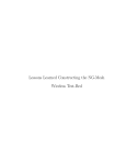
Fig. 1. The wireless network link between Oklahoma City main ITS network
and Midwest City metropolitan network.
of our experimental testing of this approach are provided in
Section IV followed by conclusions in Section V.
II. E XISTING W IRELESS D EVICES IN T HE O KLAHOMA ITS
Like that of many other states, the Oklahoma ITS network
is deployed with a fiber optic network backbone and utilizes
wireless networks where fiber optic and other wired networks
are unavailable. The specifications for the wireless equipment
in use in the Oklahoma ITS are shown in Table I. ENCOM and
Orion radio units are operated at lowest data throughput while
the Motorola Canopy equipment provides the highest data
throughput. Note that the 900 MHz and 5.7 GHz frequencies
are unlicensed and open to public use. Since they can be easily
used by the consumer devices, these frequencies are broadly
used by individuals and are subject to interference.
In addition to interference and other noise issues, security
is a significant concern when wireless networking is used
for sensitive ITS functions. Data encryption is one method
to address these security concerns. The encryption method
used by each wireless device is also shown in Table I. The
Federal Communications Commission (FCC) output power
limit for each device and their operating temperature are other
significant parameters to consider. Temperature constraints are
of particular concern when wireless devices are selected for
use in Oklahoma because its climate faces both harsh winter
and summer seasons. Equipment must be able to operate in a
wide range of temperature. Each of wireless units described in
Table I have both advantages and disadvantages for particular
ITS applications. The remainder of this section describes how
each wireless devices are deployed in three different categories
of ITS application within the Oklahoma ITS network.
A. Small Data Network Applications
The small data network category of applications is specified
to support devices at the end of the network branch. These are
typically low data transmission rate devices such as DMS or
traffic sensors. In the Oklahoma ITS, a typical deployment in
this category utilizes 900 MHz radio devices. Figure 1, shows
one such deployment. In this case, the DMSs in the Midwest
City, OK area communicate with the Oklahoma ITS network
using 900 MHz radio. This radio link is operated in a point
to multipoint configuration. This can be seen in this example
with the radio link between the I-40&29th Street location, the
DMS at I-40&Sooner Road (east bound), and I-40&Sooner
Road (west bound). For the DMSs at the I-40&Post Road
and I-40&Choctaw Road, the point to point topologies of 900
MHz radio are used to carry the control data traffic. Because
of the limitation of the line of sight between the radio links, a
repeater is installed where obstructions occur between them.
For example, the repeater at the I-40&Anderson Road is
used to retransmit the signal between the signs on Choctaw
Road and Post Road to overcome a large hill. In general, the
900 MHz radio provides a low data transfer speed that is not
suitable to carry traffic-camera video. However, for small spur
network tasks, such as DMS control, the 900 MHz radio is a
suitable as communication medium because the DMS control
commands are small data transfers. In fact, for permanent
DMSs in Oklahoma, dial-up modems are used the main
control; wireless networks are used for redundant back up.
Existing wireless network devices providing communication
backup for DMSs in the Oklahoma ITS consist of CDMA
modems, Motorola 10 Mbps Canopy and 900 MHz radio
devices. In some circumstances, wired and wireless devices
applied in a hybrid network branch. For example, a permanent
DMS on the I-44 Turnpike between Oklahoma City and Tulsa
required constructing an initial telephone cable at a cost of
USD 40,000 to connect the DMS to the telephone network
at the tollbooth approximately 2 miles away. Instead, a dialup modem was installed at the tollbooth with an auto-answer
mode configuration. This modem was in turn connected to
a 900 MHz radio. The radio pair linking the phone network
at the tollbooth and the DMS is configured for point-to-point
tunneling, bridging the data between the DMS and dial-up
modem. The small data network application configuration has
been extremely useful in the Oklahoma ITS network. It has
allowed expansion with devices at the edge of the fiber optic
network and telephone network service.
B. Medium Data Network Applications
For the medium data network category of applications, the
Canopy wireless devices with throughput of 10 or 20 Mbps
are used. Figure 1 shows an example in this category. TMC
consoles in Midwest City, OK are linked to the fiber-optic
network using a 20 Mbps Canopy. Users at both the 911 center
and the sheriff’s office can view and control the ITS cameras
without network lag. In another case, a 10 Mbps Canopy is
installed to link the main network and an individual user at the
Federal Highway Administration (FHWA) in Oklahoma City,
OK. Because the user is authorized to control both cameras
and DMSs, the data bandwidth is configured for asymmetric
40/60 uplink/downlink throughput.
In addition to these medium data rate applications, there are
other situations where 900 MHz radio devices fail to provide
adequate communication due to high noise environments with
surrounding interference. In these locations, 10 Mbps Canopy
devices are used to connect DMSs to the ITS network in
762
TABLE I
S UMMARY OF WIRELESS DEVICES USING IN THE STATE OF O KLAHOMA FOR ITS APPLICATIONS .
Orion [8]
ENCOM [9]
Motorola Canopy [10]
Motorola Canopy [11]
Model
Operating Frequency
900 MHz OFDM
902-928 MHz
COMMPAK IP
902-928 MHz
Bandwidth
Transmission Method
Modulation
Data Speed
Interface
5, 10, or 20 MHz
Fixed Frequency
OFDM, BPSK, or QPSK
5.5, 11, or 22 mbps
Ethernet(RJ-45)
30/60 Mbps Backhaul
5.47 GHz to 5.725 GHz
4.940 to 4.990 GHz
11 MHz
Fixed Frequency
BPSK,QPSK,16/64 QAM
30 Mbps or 60 Mbps
Ethernet(RJ-45)
Data Encryption
Dynamic key
AES
AES
Error Detection
Transmission power
Operating Temperature
N/A
up to +30 dBm
-20 to +55 degree C
N/A
Frequency Hopping spread spectrum
N/A
300 bps to 230.4 kbps
Ethernet(RJ-45), RS-232,
RS-422/485 (DB-9)
128 bit WEP, 128 bit WPA,
256 bit AES
32 bit CRC, ARQ
+20 dBm to +30 dBm
-40 to +75 degree C
AP, SM, or BH
5.725 GHz to 5.850 GHz
4.940 to 4.990 GHz
2.5 MHz
Fixed Frequency
FSK
10 mbps or 20 mpbs
Ethernet(RJ-45)
FEC and ARQ
+23 dBm to +30 dBm
-40 to +55 degree C
FEC and ARQ
+19 dBm to +25 dBm
-40 to +60 degree C
the same manner as in the small data network applications.
Because the Canopy provides only an Ethernet interface, an
Ethernet to serial converter is used to adapt the Canopy for
communication with the DMS. In one deployment, a DMS in
Tulsa, OK is located roughly 3 miles away from a division
office. The telephone network does not reach a point close to
the DMS. As in the application described in Section II-A, an
auto-answer dial-up modem is installed at the division office.
A pair of Ethernet-to-serial converters are used with point to
point tunneling. Using the first, a the regular dial-up modem’s
RS-232 serial signal is converted to an Internet Protocol (IP)
signal that is connected to the Canopy. At the DMS site, the
IP signal received from the Canopy is connected through the
second Ethernet-to-serial converter to change the IP signal
back into an RS-232 signal that is sent to the sign controller.
C. Large Data Network Applications
Canopy 60 Mbps equipment is used to bridge metropolitan
or other urban area to the main backbone network in the large
data network application. As an example, the ITS devices in
the Midwest City, OK area consisting of 4 analog cameras, 16
digital web cameras, 3 permanent DMSs, and TMC consoles
as shown in Figure 1. A Canopy 60 Mbps wireless link is
used to bridge the data communication between this spur
network and the ITS backbone network. In this case, the
Canopy’s data throughput is configured as symmetric (50/50
uplink/downlink) since video streams are transmitted back and
forth between the main ITS network and the spur based on user
request. This allows TMC console users in Oklahoma City and
other ares on the network to control and view camera video
in the Midwest City area and vice versa.
Wireless ITS deployments in Oklahoma have typically
depended on public mobile network services and licensefree frequency devices. While private wireless networking
using 900 MHz radio or Canopy links are the most reliable redundant network connection for DMS devices, these
approaches unfortunately can only extend to limited areas.
Since the fiber optic network does not reach the majority of
rural areas in the state, public network services are the only
available form of secondary communication between rural
DMSs and TMC consoles. This is a significant issue as these
DMSs are increasingly being used to improve public safety
through communication to travelers. In the next section, we
provide a novel wireless communication strategy that is used to
link otherwise wirelessly unreachable DMSs using an existing
private voice communication network.
III. DMS C ONTROL U SING A N E XISTING N ETWORK
T RUNKED R ADIO S YSTEM
ODOT’s 150 MHz frequency-band NTS network has been
deployed statewide, covering metropolitan, urban, and rural
areas with 96 base stations around the state. Each base station
utilizes a dipole omni-directional antenna. Coverage varies by
station with a maximum range of approximately 20 miles.
The state is divided into eight geographical regions [12] and
frequency channels are assigned to each region. The backbone
network for NTS for each region is connected together using a
wired network such as fiber optic or T-1 leased line services.
The NTS is based on the Passport protocol, a standard for
the Logic Trunked Radio (LTR) developed by Trident Micro
Systems [13]. Unlike other states that have invested in dedicated, private ITS radio networks such as 220 MHz systems,
we have utilized the NTS gateway software, TrAVL Bridge,
to connect a Skyline DMS server’s Rs-232 serial interface to
the NTS network. Trident RTU units with quarter-wave dipole
antennae are installed at each sign to translate the control Rs232 serial data back to the sign’s controller.
Both data and voice are sent using frequency modulation
(FM) on the NTS system. For communicating with DMS,
we use the data channel assigned for messaging control. This
messaging control channel uses FM 12.5 KHz narrowband
763
Link 4
Link 4
Trident RTU
Trident RTU
Link 4
Link 4
Trident RTU
Trident RTU
NTS network
Link 3
Link 2
Link 1
Skyline Server
(NTCIP Protocol)
Ethernet
to Serial
NTS gateway
(TrAVL Bridge software)
ITS Private network
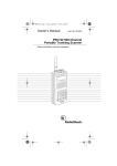
Fig. 2.
Network interface through NTS.
spacing1 . The channel is calibrated with a 1000 MHz tone for
less than a 800 Hz deviation. With this bandwidth allocation,
9600 bps data transfer should be supported. However, to ensure
reliable data communication between the DMS and the center
a 1200 bps data rate is used for DMS control.
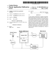
The network diagram of the DMS server software interface
to the NTS is shown in Figure 2. The NTS network is used
to provide communication between the Skyline software and
the DMS in the field using this existing wide-area radio
network. Link 1 is a network link between the Skyline server
and the NTS gateway. The link establishes IP communication
of eXtensible Markup Language (XML) data. Link 2 is a
connection between the NTS gateway and the ethernet-toserial converter. The signal output from the ethernet-to serial
converter is sent to the NTS network by Link 3. Using this
link, control data is sent to all main network areas using the
available NTS network control channel to transmit the sign
controller commands to DMSs. At the sign, an RTU unit
coverts the data back to RS-232 serial data which controls
signs via Link(s) 4.
The basic idea of this approach is to construct a system that
allows the DMS server and distant clients to operate as though
they were directly connected (using a virtual communication
port), utilizing a point-to-multipoint network. Regardless of
direction, data is presented to the NTS Network in its native
form (NTCIP protocol), conditioned for transport by the NTS
Network, and finally delivered by the NTS Network to the
target after being restored to its native NTCIP data package.
The NTS gateway identifies sign addresses in the message
from the Skyline software, and performs a database lookup to
1 FCC
Emission Designator 11K0F9W (narrowband data)
associate the target sign with a radio. The exchange is then
initiated with the correct sign.
IV. T ESTING R ESULTS OF U TILIZING THE NTS N ETWORK
A testing network was setup at the ODOT central office
by installing the NTS gateway and connecting it to the DMS
server controller. The controller did not require any special
setup since the NTS gateway software was configured to utilize
a virtual serial port. Three RTU units are installed at DMSs
in Oklahoma City: I-40 and Choctaw Road (location 1), I35 and 19th Street (location 2), and I-35 and Wilshire Blvd.
(location 3). Each location is equipped with a different DMS
model. Original communication with the DMS at location 1
was through dial-up modem and a 900 MHz radio with a 9600
bps data rate. Locations 2 and 3 have dial-up modems and
CDMA modems as their communication methods. Note that
while communication through a dial-up modem is expected
to be slower than each sign’s secondary, wireless method of
communication, the wired method is chosen as the primary
way of communicating with each DMS because it doesn’t
require transportation agents to be connected to the Oklahoma
ITS network to control a sign.
Testing was performed at each location to measure the
average latency for each communication method to accomplish
various tasks. Four different types of commands were sent to
each DMS. First, the sign status was polled checking that
the sign is operational. Polling the sign checks the status
of communication, main power, sign temperature, ambient
temperature, sign controller, LED power supplies, brightness,
control mode, and door alarm. If the sign has no malfunction,
the message “ODOT TEST MESSAGE” was sent to the sign,
764
'#!"
'!!"
&#!"
&!!"
($)"
Time (s)
($*"
($+"
%#!"
(%)"
(%*"
(%+"
%!!"
(&)"
(&*"
(&+"
$#!"
$!!"
#!"
!"
Sign Status
Post Message
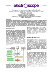
Fig. 3.
Current Message
Clear Message
Latency of sending various commands to message signs.
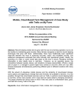
followed by a command to check the current message to
verify that the new message was correctly posted to the sign.
As last step, a final command was sent to clear the sign
before repeating the test. The communication time for the
transmission of each DMS command is shown in Figure 3.
Results are shown for each of the three locations (L1, L2
and L3) using the primary (P), secondary (S), and the NTS
network tested (T) methods of communication. As expected,
the secondary communication mechanism was always fastest
followed by the primary dial-up communication. While sending commands through the NTS network was the slowest
method of communication in each test, all tests completed in
less than 7 minutes. While this latency may be unacceptable
for many ITS functions, it is typically acceptable for the
infrequent control of a DMS.
Note that although the dial up modem operates at 9600 bps
(8 times faster than the 1200 bps rate of the tested approach),
it spends some time waiting in the initial process of original
connection. Telephone line noise reduces the achieved data
rate and can make the initial process unsuccessful. When an
initial call fails, the server will automatically call back. In our
tests, connections were always made after no more then two
tries. This make the average time for the dial up modem up to
about one minute for each category of command sent to the
sign. Unlike dial up modem, the ENCOM (900 MHz) radio
is operated at 9600 bps does not requires an initial process
to originate call. Hence, the communication time interval for
sending message to signs is shorter than utilizing the dialup modem. The NTS network can provide maximum speed at
1200 bps and needs at least 5 to 7 minutes for each transaction
to complete. It does not require a initial process to originate
call but it does require a process for NTS gateway to search
the database for the sign address (multi-drop address) and find
an available control channel to send to data to appropriate
locations. To achieve stronger signal levels, we also found
during our experiments that the RTU unit antenna needed to
be installed outside of the sign. When the signal strength
is weak, this directly effects data transition speed causing
communication delays and timeouts.
Little latency variation is seen between test performing
each of the various DMS commands. However, as the slowest
method of communication, sending the message though the
NTS network was slightly more dependent on the type (and
the length) of the command being sent. As shown in Figure 3,
each test was repeated 10 times for each sign. The results
of these experiments are shown in Figure 3 and the average
latency is reported in Table II along with the standard deviation
for each set of tests and the maximum latency for that set.
While the standard deviation in the latency of communication
through the NTS network is higher than the secondary mode,
less variation is actually seen in the NTS tests than in utilizing
the dial-up modem.
The results from our experiments demonstrate that DMS
control using the NTS network is possible. This approach
provides alternative method of wireless communication to
support ITS applications. Although the data throughput of this
approach is not high as another wireless networking methods,
it allows low-cost deployment of ITS devices at any region
statewide. Because the NTS network is privately operated for
the state’s transportation agency, there is greater confidence
of network availability during the severe weather or disaster
relative to wireless services used by the public. With the
cost shared for operation and maintenance with the existing
voice communication application, the NTS further makes ITS
network extension feasible within a limited budget.
V. C ONCLUSIONS
Wireless networks are an attractive alternative to wired
networks. They can bridge wired networks in several different
network topologies such as those we have described as small,
765
TABLE II
S UMMARY OF AVERAGE TIME , STANDARD DEVIATION , AND MAXIMUM TIME FOR COMMUNICATION TO DIFFERENT SIGN LOCATIONS THROUGH
DIFFERENT NETWORK TYPES ( TIMES IN SECONDS )
Communication
Data rate(bps)
Sign status(Avg.)
Sign status(SD)
Sign status(Max.)
Post message(Avg.)
Post message(SD)
Post message(Max.)
Current message(Avg.)
Current message(SD)
Current message(Max.)
Clear message(Avg.)
Clear message(SD)
Clear message(Max.)
Location 1
Primary
Dialup
9600
60
3.32
65
65
5.23
73
59
3.03
65
55
4.71
62
Location 1
Secondary
ENCOM
9600
40
2.57
43
41
2.14
44
35
1.95
38
38
2.57
42
Location 1
Testing
NTS
1200
350
3.55
357
340
3.97
347
310
3.22
314
300
3.29
305
Location 2
Primary
Dialup
9600
69
4.52
75
66
4.02
75
55
3.46
60
70
2.61
74
medium and larger data network applications. In order to
reduce the investment cost, and improve data reliability and
security, we have provided a new way use of an existing NTS
radio to provide communication to DMSs. The results from
our tests show that we can use the NTS as network medium
to control NTCIP-protocol-based signs. Due to the small size
of control messages, this data can be sent to through the NTS
network using available control channels without interrupting
the primary voice service. However, this DMS control is slow
due to the maximum data rate at 1200 bps. Communication
using our presented approach takes longer than that through
telephone and CDMA modems where the data speed is 9600
bps. While this may appear slow compared to other networks
but it is an extremely inexpensive way to implement ITS
devices statewide including in rural regions. Sharing the NTS
network for voice and data traffic also divides the cost of
operation and maintenance. Other suitable low data rate ITS
applications to utilize the NTS network include traffic sensors
and portable DMSs Both need only to transfer a few bytes
of data to TMC consoles. These traffic sensors and portable
DMSs also frequently deployed in work zone areas. Data from
devices monitoring traffic in these temporary locations can be
easily communicated to the TMC via the NTS network. In
the future, if the demand of the data is more than the control
channel can support, it would also be possible to dedicate a
voice channel for data use.
ACKNOWLEDGMENT
The authors would like to thank Alan Stevenson, ODOT
ITS and Fiber Optic Engineering Manager, for his continued
support of the OU ITS Lab. We would also like to thank
Ty Todd, communication system manager at ODOT, who
generously provided technical information regarding the NTS
network. The authors would like express their appreciation
to Dave Anderson, President/CEO at Trident Micro Systems,
who permitted us to disclose the experimental results of
communication with DMSs through the NTS network and
Location 2
Secondary
CDMA
UDP
10
2.05
14
9
1.73
12
5
1.48
8
8
1.34
101
Location 2
Testing
NTS
1200
360
3.03
366
400
3.87
406
390
3.55
397
410
2.76
414
Location 3
Primary
Dialup
9600
71
3.10
75
75
4.38
82
69
3.16
75
68
3.13
75
Location 3
Secondary
CDMA
UDP
15
2.37
19
10
1.79
14
9
1.41
12
7
1.55
10
Location 3
Testing
NTS
1200
350
3.55
357
320
2.37
325
390
2.57
394
310
3.19
315
provided testing equipment.
R EFERENCES
[1] Columbia Telecommunications Corporation, “Brief engineering assessment: Efficiencies available through simultaneous construction and colocation of communication conduit and fiber,” The National Association
of Telecommunications Officers and Advisors and The City and Country
of San Francisco, Tech. Rep., August 2009.
[2] Intelligent transportation systems (its) operations. Visited April, 2011.
[Online]. Available: http://www.wsdot.wa.gov/Operations/ITS/
[3] A. Amanna, “Assessment of current and emerging broadband wireless
technologies for VDOT’s operations program,” Virginia Tech Transportation Institute, Tech. Rep., Jun 2008.
[4] B. Kilani, E. Vorakitolan, J. Havlicek, M. Tull, and A. Stevenson,
“Distributed ITS control and the oklahoma virtual TMC,” in Proceedings
of the 12th International IEEE Conference on Intelligent Transportation
Systems, Missouri, USA, Oct. 2009, pp. 785–790.
[5] FCC rules for unlicensed wireless equipment operating in the ISM
bands. Visited April, 2011. [Online]. Available: http://www.afar.net/
tutorials/fcc-rules/
[6] M. Fitz, J. Krogmeier, J. Grimm, J. gansman, T. Chen, and T. Magnusen, “The 220 MHz ITS spectral allocation: Potential, pitfalls, and
applications,” IEEE Communicaitons Magazine, pp. 42–54, 1996.
[7] J. Grimm, M. Fitz, J. Krogmeier, T. Chen, T.Magnuse, J. Gansman,
and W. Kuo, “High efficiency narrowband wireless modems for ITS
applications,” ITS Journal, vol. 3, no. 4, pp. 333–352, 1997.
[8] Orion 900 MHz OFDM user manual. Visited April, 2011.
[Online]. Available: http://www.wirelessinteractive.com/pdf/radios/
Orion900 manual.pdf
[9] ENCOM
COMMPAK
IP
900
MHz
and
2.4
GHz
serial/ethernet
bridge.
Visited
April,
2011.
[Online].
Available: http://www.encomwireless.com/document-centre/doc view/
142-commpak-ip?tmpl=component&format=raw
[10] Canopy backhaul module user manual. Visited April, 2011. [Online].
Available: http://www.canopy-wireless-solutions.com/AppicationNotes/
BHManualIss5.pdf
[11] 4.9 GHz wireless ethernet bridges. Visited April, 2011. [Online].
Available: http://www.canopy-wireless-solutions.com/AppicationNotes/
MotorolaPTP49400BridgeTechnicalSpecifications.pdf
[12] Oklahoma departemnt of transporation radio reference. Visited April,
2011. [Online]. Available: http://www.radioreference.com/apps/db/?sid=
5253
[13] PassPort trunking. Visited April, 2011. [Online]. Available: http:
//www.tridentms.com/Home/PassPortTrunking/tabid/61/Default.aspx
766