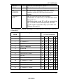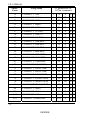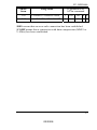
1
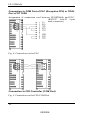
FP- ISDN64k
Limitation of liability
The present Instruction Manual was compiled with extreme care.
The specifications and descriptions given herein are applicable to
the FP-Modem 14.4 at the moment of printing. Subsequent designs
of the modem as well as the pertinent manuals are subject to
changes without prior notice. Matsushita Automation Controls will
not accept any liability for damages directly or indirectly arising out
of probably existing incorrect statements or omissions in the
documentation or discrepancies between modem and manual.
Copyright
The present publication is protected by copyright. All rights are
reserved. Parts of this manual should neither be reproduced in any
way by photocopy, microfilm or other techniques nor converted
into a form suitable for machines, in particular, for data processing
installations without written consent given by Matsushita
Automation. Liability assumption for the infringement of patents
cannot be derived from the use of information contained in this
manual.
Trademark
V.42bis has been licensed under U.S. Patent 4,558,302.
Hayes is a registered trademark of Hayes Microcomputer Products,
Inc.
1
02/2008
FP- ISDN64k
Table of contents
Limitation of liability ................................................................ 1
Copyright................................................................................... 1
Trademark ................................................................................. 1
TABLE OF CONTENTS .........................................................2
A SURVEY .............................................................................4
ISDN – What Is That ? ............................................................... 5
About Digital and Analog Data ............................................ 5
ISDN Modem ........................................................................ 5
S0- Bus: The ISDN Interface at the Subscriber .................... 6
D- and B-Channels: What is Going on at the S0-Port ?........ 6
ISDN Services and Protocols................................................ 6
MSN or EAZ ......................................................................... 7
CAUSE, Error Messages in ISDN ........................................ 8
Communication Methods and Protocols ................................. 8
ASCII Code ........................................................................... 9
Error Correction and Data Compression .............................. 9
Transmission Modes ........................................................... 10
Terminal Adapter Control................................................... 10
Messages ............................................................................. 11
Protocols.............................................................................. 11
LET’S START.......................................................................12
The FP- ISDN 64k..................................................................... 13
Scope of Supplies..................................................................... 13
Connections and Indicators...................................................... 13
Possible Connections to a Matsuhita PLC............................... 14
TOOL Port (programming port) ............................................. 14
COM Port (optional user-programmable communication port)14
The Data Interface of FP- ISDN 64k ...................................... 15
Connection to a Computer (PC).......................................... 15
Connection to COM Port of PLC (Exception FP0) or TOOL
Port of FP 10SH .................................................................. 16
Connection to FP0 Controller (COM Port) ........................ 16
Connection to TOOL Port of PLC (FP0, FP-M, FP-C)...... 17
Connection to FP1/FP3 Controller (TOOL Port) ............... 17
2
02/2008
FP- ISDN64k
Installation............................................................................... 18
OPERATION OF THE FP-ISDN64K...................................19
AT Commands According To Hayes...................................... 20
Syntax ...................................................................................... 20
The Memories of FP-ISDN64k................................................ 21
Basic Commands For Operation ............................................ 22
Dial Commands .................................................................. 22
Default settings ................................................................... 23
Store Commands................................................................. 24
Sequence Of Data Transmission ............................................. 25
Establishing Connection (Handshaking)............................ 25
Abort Connection ............................................................... 26
Password Protection and Ringback Function ...................... 26
Configure Password and Ringback Function ..................... 26
Report Passwords and Ringback ........................................ 27
Enable/Disable Password/Ringback Function ................... 27
Handshaking upon PW/RR................................................. 27
Leased Line Mode..................................................................... 28
Leased Line Mode Controlled by Terminal Station........... 28
Automatic Leased Line Mode After Power On ................. 28
Advice to the Leased Line Topic ....................................... 29
Other Configuration Commands ........................................ 29
Delete Leased Line Configuration ..................................... 29
Troubles In The Operating Voltage ....................................... 29
FP-ISDN64k Messages ............................................................. 30
AT- COMMAND SET SUMMERY ........................................34
THE FUNCTION OF S-REGISTERS ...................................40
TECHNICAL DATA AND CERTIFICATION .......................45
Factory Default Settings .......................................................... 46
Certification ............................................................................. 47
S0 Standard Connection RJ12-RJ45 ........................................ 47
Modem Specifications ............................................................. 48
ISDN Error Messages (CAUSE) ............................................. 49
Technical Terms ...................................................................... 51
3
02/2008
FP- ISDN64k
1
A Survey
This section of the Instruction Manual was particularly written for
beginners and deals with the fundamental mode of function of
ISDN, of an ISDN connection and of the terminal adapter FPISDN64k.
4
02/2008
FP- ISDN64k
ISDN – What Is That ?
About Digital and Analog Data
Within a computer or a PLC, the data are transmitted in digital form
between the individual components (processor, I/O units, storage
medium etc.) and processed. Digital means transmission by
electrical pulses which may take two states, either ON or OFF
(HIGH or LOW, ONE or ZERO). These signals show a constant
amplitude, mostly amounting to 0 volts in OFF state and 5 volts in
ON state. They are called BITS and represent the smallest units of a
digital signal.
These bits can be transmitted and processed either individually one
following the other or gathered in groups (for instance, 8 bits of one
group are called BYTE). In the first instance, serial processing and,
in the other instance, parallel processing are concerned.
The most widespreadly known transmission medium for signals,
namely the telecommunication network, has been established for
the transmission of language i.e. of analog data. If one intends now
to transmit the information required for modern data processing in
computers through this network, the data shall be converted for this
purpose. The modem is exactly this converter and represents the
link between the digital environment of computer and the analog
environment of the telecommunication network.
A modem is a device for performing the conversion of digital
signals into analog signals and vice versa. Modem is an
abbreviation and means MOdulator-DEModulator. The digital data
signal is modulated on an analog carrier and demodulated again in
the receiver. The method of modulation has to be selected so that as
much data as possible can be transmitted without exiting the
frequency range predefined by the transmission channel (telephone
line). Exchange of information has to be ensured without any
losses.
ISDN Modem
Since the telecommunication network has been increasingly
extended and converted in a digital way, the subscriber should also
have the possibility of a digital connection offered. To this end, a
special exchange standard was developed i.e. the ISDN. All
5
02/2008
FP- ISDN64k
information will be transmitted there digitally. If an analog
subscriber calls a digital one or vice versa, the analog signals are
converted into digital data at the exchange (digital/analog
conversion). If a subscriber has got a digital ISDN connection, it is
not possible without more ado to connect an “obsolete” analog
terminal unit, for instance, a modem (with an additional device
only). Since, however, computers and PLC
systems etc. need a modem for communication, special ISDN
modems have been developed, so-called terminal adapters. These
terminal adapters function with the terminal unit as compared to
their brothers, however, they must not convert the user data for
transmission into analog data but are processing them digitally in
the transmission protocol selected.
S0- Bus: The ISDN Interface at the Subscriber
The ISDN network is connected to the subscriber through an NTBA.
A basic connection with a so-called S0-interface is made available
on this device. The terminal units, such as ISDN phone or ISDN
terminal adapter are connected to this S0-port. When several
connection outlets are installed alongwith the NTBA, this port is
called S0-bus. This bus is comprised of 4 lines, two for transmitting
data and two for receiving data. As compared to an analog
connection, this bus cannot be extended as you like. The wires
should not be interchanged in the wiring and matching resistors
shall be provided at the bus terminations.
D- and B-Channels: What is Going on at the S0-Port ?
1 D-channel and 2 B-channels are made available to the subscriber
at a basic connection port. The D-channel has a data throughput rate
of 16,000 bps and the B-channel of 64,000 bps. ISDN protocols
were defined to make use of these channels. Whereas the protocol
in D-channel ensures exchange of information required for a
connection between terminal unit and exchange offices, the
protocols in B-channel are responsible for mutual communication
between the terminal units involved in the connection.
ISDN Services and Protocols
The D-channel protocol DSS1 (EURO-ISDN) or 1 TR6 (old ISDN
standard of Telekom) is split up into 3 layers. In the D-channel,
among others, the connection port is checked, the telephone
6
02/2008
FP- ISDN64k
number, the own connection number and the desired ISDN service
are exchanged in the B-channel between exchange office and
terminal unit, however, user data are not transmitted !
The following ISDN services are available:
ISDN service
Who needs this service?
3.1 kHz
Audio transmission
ISDN phones and all analog units
connected to an S0 via additional hardware
(A/D converter)
Data transmission
64,000 bps
ISDN-PC boards, all terminal units for data
transmission and FP-ISDN64k
Telefax group 4
ISDN facsimile machine with 64,000 bps
X.31
Data transmission in D-channel, to be
ordered separately
Notice !
A transition of services from data transmission at 64,000 bps to
audio transmission at 3.1 kHz is not possible. Therefore, a
phone cannot be called with a terminal adapter to test the
installation, that is, communication between ISDN data
terminal units is only possible !
The B-channels can be simultaneously operated separately from
each other with various services. Coordination of B-channels is
effected by the D-channel. In the data service at 64,000 bps, other
protocols are available for data transmission which are also
supported by FP-ISDN 64k: X.75, X75-T.70NL, V.110, BTX,
HDLC. For data transmission, the B-channels can be grouped to
achieve a higher data throughput rate (2x64,000 bps).
MSN or EAZ
Three different phone numbers can be allocated to one EUROISDN main connection. If several terminal units of the same service
identifier code (e.g. 64,000 bps/data) are connected to one
connection port, but each unit has to be accessible, each unit shall
get another phone number, also called MSN.
As to the elder 1 TR6 ISDN model, there is only the possibility to
indicate the last cipher of phone number as distinctive feature (0-9).
In the 1 TR6 protocol, this cipher is named EAZ.
7
02/2008
FP- ISDN64k
CAUSE, Error Messages in ISDN
The ISDN offers quite a number of error messages also evaluated
by the FP-ISDN 64k and output to the terminal unit. If a subscriber
to be called-up is busy, no busy tone is sent by the exchange, but
the error message 0x34B5 is transmitted in the D-channel. The
terminal adapter can then output the BUSY message to the terminal
unit. Since suitable message codes are not available for all ISDN
error messages, the CAUSE errors can be visualised by means of
the “AT%Y1” command (survey on page 49).
Communication Methods
and Protocols
The data flow processed by the ISDN modem is comprised of two
different components. On the terminal unit side to the controller
(computer, PLC ...) either data or control commands for the ISDN
modem are being transmitted. In the ISDN part to the
telecommunication network, a high data throughput has to be
achieved and occurring errors have to be corrected. Various
methods and protocols are applied to this end.
The transmission rate is mainly dependent on the rate between
terminal unit and ISDN modem. On the transmission side in the
ISDN network, always one B-channel is assigned to 64,000 bps.
The following ISDN standards are supported by FP-ISDN64k:
•
64,000 bps transparent – full duplex, without data backup or
data compression protocol
•
X.75 – full duplex, with data backup
•
X.75-T.70NL- same as X.75, with additional network protocol
•
V.110 – full duplex, 300 to 56,000 bps, without data backup,
only standardised from 1,200 to 9,600 bps, asynchronous
transmission
•
HDLC – data transmission protocol
•
PPP/SLP – transmission protocol for TCP/IP networks (e.g.
Internet), working on HDLC connections
8
02/2008
FP- ISDN64k
ASCII Code
During data transmission through a terminal adapter, a definite
combination of 8 bits is used to represent individual characters.
This standard developed over many years is called ASCII code. The
original ASCII table contains 128 characters only (letters, ciphers,
special characters) and could also be represented by a group of 7
bits instead of 8 bits: the most significant bit is always 0. In the
ASCII representation, this eighth bit is superfluous, however, it is
generally transmitted since the computer is processing the data
internally on an 8-bit basis (BYTE). When using your modem, you
might ascertain that there is a possibility of choice between 7 bits or
8 bits ASCII in some transmission modes.
Error Correction and Data Compression
During transmission, errors may occur due to interference noise or
to distortion of digital signals. To ensure high data safety, the data
are incorporated in an error protocol, that is, information will be
added to the actual data enabling the receiver modem to detect
errors and to correct them, if necessary.
On exchange side, such ISDN standards as X.75 or HDLC are
being applied. The standard V.42 LAPM and MNP2-4 correction
methods can also be used between two terminal adapters. If the
V.42 mode has been activated, the terminal adapter transmits a
definite character string to detect which configuration is enabled by
the remote station and then selects LAPM or MNP according to the
requirements.
By means of the FP-ISDN64k, you have also the possibility to
enforce a connection under MNP or LAPM, provided that one of
the two correction modes is supported.
In order to transmit still more data per time unit, the data flow can
be additionally compressed. V.42bis and MNP5 re used as relevant
methods. In dependence on the type of data to be transmitted, the
rate can be partially more than triplicated.
The FP-ISDN64k is configuring itself during the establishment of
connection in dependence on the preset transmission mode and
adjusts the methods possible with the remote station.
9
02/2008
FP- ISDN64k
Transmission Modes
Nine different modes can be adjusted for data transmission through
ISDN network:
•
DIRECT mode: Transmitted / received data buffer disabled,
transmission rate to the controller is matched with the
connection speed, no error correction, no data compression
•
NORMAL mode: Transmitted / received data buffer, no error
correction, no data compression
•
RELIABLE mode: Transmitted / received data buffer,
functions only with error correction either according to LAPM
or MNP2-4, the terminal adapter hangs up if the remote
modem does not admit of an error correction, data compression
according to V.42bis or MNP5 is possible
•
AUTO-RELIABLE mode: Transmitted / received data buffer,
automatic selection of the error correction method according to
V.42 or MNP, if the remote modem does not admit of an error
correction, NORMAL mode is applied, data compression
according to V.42bis or MNP 5 is possible
•
In addition, the ISDN protocols already described, such as
X.75, are available.
Terminal Adapter Control
Interfacing with the controller (computer or PLC) also often called
DTE (Data Transmission Equipment) is effected through a serial
asynchronous RS232 interface. Adjustment of the interface
parameters, such as rate and number of the data and control bits, is
made automatically in the terminal adapter in accordance with the
standard parameters preset by the controller.
The control of terminal adapter follows the AT-Hayes command
set. The commands are transmitted from the controller to the
terminal adapter in form of ASCII data. These commands can be
sent from a control program or entered manually via terminal
program.
Basic configurations have been stored in the terminal adapter which
make possible instant use without any configuration. The dial
commands only shall be sent to the modem from the controller.
10
02/2008
FP- ISDN64k
If an adaption to various operating conditions is required, the
operating parameters of the terminal adapter can be adjusted and
saved by means of the AT commands.
Messages
In responding to the control commands and upon errors occurred,
the terminal adapter generates messages enabling the controller to
check the execution of commands and to supervise the operating
state. These messages are sent in ASCII format as text or as ciphers.
Protocols
The term “Protocol” combines quite a number of rules defining the
characteristics of the data signals for transmission. During the
communication between two computers, both computers shall
function according to a uniform protocol to ensure correct
interpretation of the signals communicated.
The protocols are an integral part of the computers’ communication
software. A protocol featuring enhanced data safety is Z-MODEM.
11
02/2008
FP- ISDN64k
2
Let’s Start
In this section, you will find general information about the
installation of FP-ISDN64k. Please study these instructions
carefully prior to putting into operation.
12
02/2008
FP- ISDN64k
The FP- ISDN 64k
The FP-ISDN 64k supports communication and data exchange with
other computers/controllers through the ISDN network. The
terminal adapter is operated with the standard commands according
to Hayes and can be easily adapted to the respective system.
Scope of Supplies
The scope of supplies of the terminal adapter includes:
•
•
•
FP-ISDN 64k
Telephone connection cord RJ12 to RJ45
User manual
If one of these items is found defective or is completely missing,
please raise claims immediately.
Connections and Indicators
Fig. 1: Front view of FP-ISDN 64k
1
2
3
4
S0 connection jack (RJ12) for dial and
leased line, assignment of cable, see
page 47
LED DCD - Data Carrier Detect, is
lighting upon established data
communication, LED extinguishes
after Power On after approx. 1 second
LED Power / Test – is lighting upon
operating voltage applied, when this
LED remains OFF or is flashing after
Power On, the modem is defective
and has to be replaced
Jack BU1 for operating voltage
+24VDC, the GND pins are linked
internally
ATTENTION: Note polarity.
13
02/2008
FP- ISDN64k
Possible Connections to a Matsuhita PLC
You may connect the FP-ISDN64k either to the “TOOL Port”
(programming port) or to the “COM Port” (optional second userprogrammable communication port).
TOOL Port (programming port)
Upon connection to the TOOL port, the modem interfacing shall be
adjusted in the system register 411 of PLC (see Programming
Software Manual).
Then, the terminal adapter is automatically initialised by the PLC
by setting the FP-ISDN64k register S0 = 1. The terminal adapter
then receives arriving calls automatically so that you may have
access to the PLC after establishment of connection from the
remote PC (or any other controller).
How to protect your PLC from unauthorised access, please read
section Password Protection and Ringback Function on page 26.
For maximum safety (access protection “on-site”), you may also
store a password in the PLC.
COM Port (optional user-programmable
communication port)
The second additional RS232C port of the PLC also makes
available the function described above. In addition, this port is userprogrammable, that is, you may transmit and receive any data in
any format and even switch-over between both modes during
operation.
The following shall apply in general:
a)
If the PLC is to establish an active connection by itself, you
have to connect the FP-ISDN64k to the additional COM port
(communication port).
b) Suffice it to wait for a call, you may connect the terminal
adapter to both ports. After establishment of connection, you
will have full access to the PLC in both cases, that is, you may
either read or write data.
14
02/2008
FP- ISDN64k
The Data Interface of FP- ISDN 64k
The connections of serial interface comply with the V.24 standard
with V.28 level. The following signals are used:
1- RxD, is the received data line at FPISDN64k and shall be connected to
RxD of the PLC
2- GND (signal ground)
3- TxD, is the transmitted data line at FPISDN64k and shall be connected to
TxD of the PLC
5
Jack BU 2 – serial interface for
interfacing with the controller
(computer / PLC)
Fig. 2: Bottom of the device
Connection to a Computer (PC)
Assignment of a connection cord between FP-ISDN64k and PC
(V.24/V.28 or RS232C Sub-D 9-pin female connector)
Fig. 3: Connection cord for
PC
15
02/2008
FP- ISDN64k
Connection to COM Port of PLC (Exception FP0) or TOOL
Port of FP 10SH
Assignment of connection cord between FP-ISDN64k and PLC,
(RS232C Sub-D 9-pin
male connector)
Fig. 4: Connection cord to PLC
Connection to FP0 Controller (COM Port)
Fig. 5: Connection cord to FP0 COM Port
16
02/2008
FP- ISDN64k
Connection to TOOL Port of PLC (FP0, FP-M, FP-C)
Assignment of connection cord between FP-ISDN64k and TOOL
Port of above FP
controllers (RS232C
miniature DIN 5-pin male
connector)
Fig. 6: Connection cord
to TOOL Port
Connection to FP1/FP3 Controller (TOOL Port)
Assignment of connection cord between FP-ISDN64k and FP1/FP3
cable (TOOL Port ↔ PC) (RS232C Sub-D 25-pin male connector)
Fig.7: Connection cord to
TOOL Port
17
02/2008
FP- ISDN64k
Installation
The FP-ISDN64k has been conceived, among others, for use on
DIN rails of 35 mm (top-hat rail). For installation, please proceed
as follows:
•
•
•
•
Install terminal adapter and PLC on the top-hat rail
Connect the data lines (jack BU2) to the PLC and the telephone
cord to the S0 outlet
Connect the terminal adapter to the 24V DC operating voltage
(jack BU1).
Switch-on the power supply unit.
After switching-on the device, the LED „POWER/Test“ for selftest extinguishes after approx. 2 seconds. After successful Power
On self-test, the LED „POWER/Test“ is lighting permanently.
In case of a flashing or dark LED „Test“, the terminal adapter is
defective and has to be replaced.
18
02/2008
FP- ISDN64k
3
Operation of the
FP-ISDN64k
In this section, the use of AT commands and registers is described
and the basic commands are introduced. The sequence of a data
transmission is explained, too.
19
02/2008
FP- ISDN64k
AT Commands According To Hayes
The terminal adapter FP-ISDN64k is operated from the controller
(computer, PLC, ...) by means of the AT commands according to
Hayes standard regardless of the fact whether these commands are
transmitted from a control program or from a terminal program by
manual input. The terminal adapter is in the command mode
reached after switching-on and ending a connection. The terminal
unit rate is detected automatically up to a rate of 57,600 bps and a
data format of 8 data bits, with no parity and 1 stop bit (8N1).
After establishment of connection, automatic changeover to data
mode is effected. With the Escape command +++, you may go from
this mode to command mode. Return to data mode is possible with
ATO.
The commands are sent in ASCII code. A complete list of available
commands is given in section “AT Commands Summary”. For
reasons of compatibility, commands are included that can be
executed, however, do not have any effects, such as e.g. AT M...,
AT L...(no speaker) and AT DT...(no tone dialing possible in
ISDN).
Most settings are stored in the terminal adapter so that the
command sequences are restricted to a minimum extent in normal
mode (telephone number or memory location of telephone number).
If the changes which you make by the input of AT commands
adversely affect the functionality of your FP-ISDN64k, you can
reload the factory default settings with ATCLEAR.
Syntax
All Hayes commands begin with the ASCII character AT (English
abbreviation for: Attention). These characters are parsed by the
terminal adapter, decoding the command flow. The data format
should be 8 data bits, no parity, 1 stop bit (other formats are
adjusted through the S-registers S60/S61). The terminal adapter
interprets all successive characters as commands. After an AT,
several commands (max. 58 characters) can be grouped together in
a sequence. The input is terminated with Return/Enter and the
control sequence is then sent to the terminal adapter.
20
02/2008
FP- ISDN64k
The terminal adapter confirms with "OK" or with the respective
value in case of queries. If the instruction could not be executed, the
message "ERROR" is output.
The AT commands can be entered either in upper case or lower
case, however, not in a combination of both cases. Erroneous inputs
can be deleted with the backspace key. The AT characters at the
beginning of the line cannot be deleted.
The Memories of FP-ISDN64k
The FP-ISDN64k has got different memories to save programs and
data to maintain its functionality. On the one hand, the contents of
these memories are partially fixed-programmed, on the other hand,
they can be edited by AT commands for individual adaption of the
terminal adapter. The alterable data are contained in the S-registers.
One can distinguish between three memory levels:
Program
memory
ROM
AT&F0 →
AT&F1 →
Main
memory
RAM
AT&Wn →
← ATZn
Power on:
← AT&Yn
User
memory
EEPROM
The Program Memory in which the overall sequence of functions
and the preset data of the FP-ISDN64k have been stored is a ROM
(Read Only Memory) that can be read only. To load the default
settings, enter command AT&F3, to erase all memory areas, enter
ATCLEAR and then wait approx. 2 seconds. All settings in the unit
are deleted by means of this command !
The User Memory in which the data of the S-registers (profile 0
and profile 1) modified by the user have been stored is an
EEPROM (Electrically Erasable Programmable ROM). This
memory can be written and will save the data even after disabling
of the FP-ISDN64k. After you have edited the contents of Sregisters, they are written in the user memory by AT&Wn. By
means of the AT&Yn command, you may define which of both the
settings shall be selected for use when enabling the FP-ISDN64k.
By means of ATZn, you may release a software RESET and load
the profile(n).
21
02/2008
FP- ISDN64k
Furthermore, telephone numbers can be stored in the user memory
by means of the AT&Z(n)=x command, whereby x may have a
length of up to 15 characters.
The Main Memory of the FP-ISDN64k is a fast write/read memory
of the RAM type (Random Access Memory) that is used during
operation. After enable, a RESET or ATZn, data are loaded from
the user memory or the data of default settings are loaded by means
of AT&F3.
By means of the AT&V command, the active configuration (in
main memory) and, by means of the AT\S command, the most
essential settings with prompt texts can be reported.
Basic Commands For Operation
The following commands are the basis for operation and will
generally suffice. A part thereof can be saved in the user memory
so that the sequences of operation are restricted to a few commands
only. The AT preceding the commands was omitted in the tables.
When the FP-ISDN64k is in data mode, toggling to command mode
is possible with the Escape sequence +++ (without AT !!). For
return to data mode, ATO is sent.
Dial Commands
ATDn is the general dial command that can be modified with the n
options.
D
DP
DT
D,
Dial command
Pulse dialing; ignored in ISDN
Tone dialing; ignored in ISDN
Dial pause, the time is specified by S8 register, then, the
dialing cycle is resumed
DW
Wait for dial tome; ignored in ISDN
DSx Dials the number stored in the directory, x stands for shortcode dial number, for instance: ATDS1 dials the number
stored by AT&Z1
DL
Re-dial last number
D0-D9 Dials reported ciphers, *,#,A,D possible upon tone dialing
D...; Semicolon at the end of number, modem goes to command
state after establishment of connection (same as +++)
22
02/2008
FP- ISDN64k
H
Interrupts a current connection, the modem goes "on-hook"
Default settings
S99=0 Definition of ISDN-D-channel protocol to DSS1 (EUROISDN)
%Z=n Probable definition of an MSN number at DSS1 (see page
7)
S99=1 Definition of ISDN-D-channel protocol to 1 TR6 (old
national standard)
S96=n Probable definition of an EAZ number at 1 TR6 (see page
7)
F70\N6 Selects B-channel X.75 with data backup duplex
F64
Select B-channel V.110 with 9,600 bps duplex
Xn
See tables FP-ISDN64k Messages as from page 30
F255 Select auto-detect mode for B-channel
F60
Select B-channel V.110 with 300 bps duplex
F61
Select B-channel V.110 with 1,200 bps duplex
F62
Select B-channel V.110 with 2,400 bps duplex
F63
Select B-channel V.110 with 4,800 bps duplex
F64
Select B-channel V.110 with 9,600 bps duplex
F65
Select B-channel V.110 with 19,200 bps duplex
F66
Select B-channel V.110 with 38,400 bps duplex, not
standardised
F67
Select B-channel V.110 with 48,000 bps duplex, not
standardised
F68
Select B-channel V.110 with 56,000 bps duplex, not
standardised
F70
Select B-channel with 64,000 bps duplex, used for X.75
(AT\N6)
\N0
Select NORMAL mode:
no error correction, no data compression
\N1
Select DIRECT mode:
interface port rate is matched with transmission rate, no
error correction, no data compression, required for V.110
\N2
Select AUTO-RELIABLE mode:
terminal adapter hangs up if the remote modem does not
admit of an error correction, error correction first according
to LAPM and then to MNP, data compression according to
V.42bis or MNP5 possible (AT%Cn)
23
02/2008
FP- ISDN64k
\N3
\N4
\N5
\N6
Q0
Q1
V0
V1
Select AUTO-RELIABLE mode:
operation in NORMAL mode when the remote modem
does not admit of an error correction, error correction
method according to V.42 or MNP, data compression
according to V.42bis or MNP5 possible (AT%Cn)
Select RELIABLE mode:
error correction according to LAPM only, otherwise,
terminal adapter hangs-up, data compression according to
V.42 possible (AT%Cn)
Select RELIABLE mode:
error correction according to MNP only, otherwise,
terminal adapter hangs-up, data compression according to
MNP5 possible (AT%Cn)
Select X.75:
most commonly used ISDN protocol (transmission method
in B-channel to ATF70)
Modem messages are sent
Modem messages are suppressed
Modem messages are output numerically (terse)
Modem messages are output as text (verbose)
Store Commands
Sn
Sn?
Sn=x
&F3
&V
Selects register with the number n
Reports the value of register with the number n
Sets register with the number n to value x
Factory default configuration loaded from database3
Reports settings of current and two user-defined
configurations. The first four stored telephone numbers are
reported additionally
&W0 Stores the current configuration in user profile 0
&W1 Stores the current configuration in user profile 1
&Y0 After RESET or upon power-up of modem, the
configuration of user profile 0 will be used
&Y1 After RESET or upon power-up of modem, the
configuration of user profile 1 will be used
&Zn=x Stores 20 telephone numbers (n=0...3), x max. 34 characters
Z0
Releases software RESET (warm RESET) and restores the
configuration of user profile 0
Z1
Releases software RESET (warm RESET) and restores the
24
02/2008
FP- ISDN64k
configuration of user profile 1
Sequence Of Data Transmission
Controller and terminal adapter are ready to operate. The telephone
connection cord has been linked with the ISDN socket outlet. The
sequence will be explained for connection to a subscriber’s station.
Establishing Connection (Handshaking)
Typical dial command for an analog modem:
The controller sends ATDT0W 0999 12345 <CR> to the modem.
AT initiate command
DT – dial with tone dialing
0W – subscriber’s station gets an exchange
0999 12345 – target telephone number
<CR> - terminate command
This dial command can also be used for the FP-ISDN64k. The
commands “T” (tone dialing) and “W” (wait for exchange) do not
exist in ISDN. They are simply ignored by the terminal adapter.
The FP-ISDN64k starts dialing. After the subscriber’s station goes
off-hook, the handshaking protocol is run between the two terminal
adapters. The used protocols are declared therein. If the connection
was established successfully, the terminal adapter reports to the
controller the line speed and the type of error protocol used. Then,
the terminal adapter gioes to data mode. The DCD-LED starts
lighting.
In data mode, the FP-ISDN64k transmits information to be
exchanged directly from the controller to the remote terminal
adapter or vice versa.
The data connection cannot be established if the two devices cannot
detect a transmission method that can be used by both or if
extremely severe interferences occur. The FP-ISDN64k responds
with NO ANSWER. If the DTE sends characters during the
connection phase, the modem goes on-hook and responds with NO
CARRIER.
When the FP-ISDN64k is called, it will send the ASCII RING
string to the controller at every ring. If a number higher than zero
has been adjusted in the S0 register, the FP-ISDN64k goes off-hook
25
02/2008
FP- ISDN64k
after expiration of this number of rings. Now, the handshaking
protocol commences, as described above.
With S0=0, the FP-ISDN64k remains in inactive state.
Abort Connection
The data connection is maintained until the FP-ISDN64k
•
•
•
•
•
has got the command for on-hook (+++ ATH) from the
controller, response NO CARRIER
the exchange interrupts the connection (too severe
interferences, remote station not active any more, ...), response
NO CARRIER
a BUSY signal (busy tone) has been detected, response BUSY
has got an abort sequence from the remote terminal adapter,
response NO CARRIER
causes for abort or errors are reported in the ISDN by CAUSE
messages (survey in annex on page 49)
Password Protection and
Ringback Function
To protect the controller linked with the FP-ISDN64k and the data
saved therein from unauthorised access, you can install an access
and user check by means of the Password/Ringback Function
(PW/RR).
Two levels of safety are possible:
Level 1:
Level 2:
Access only with valid password
Access only with valid password and ringback to the
stored number
20 storage locations are available for PW/RR in which a
combination of both levels can be used, too.
Configure Password and Ringback Function
First define the master password by means of which the PW/RR
function can be enabled/disabled. The master password is defined
in the short-code dial register Z0 (do not forget the “/” character
before the PW). Example:
AT&Z0=/MASTER
26
02/2008
FP- ISDN64k
Hereunder you may define your access passwords and, if required,
the ringback numbers in the short-code dial registers Z1-Z19. If no
ringback function has to be allocated, the ringback number before
the password shall be omitted.
Example without ringback:
AT&Z1=/SECRET
Example with ringback:
AT&Z2=0123456/GEIGE
In both cases, do not forget the separator character “/” before the
PW.
Report Passwords and Ringback
AT&Z? all passwords and ringback numbers are reported (with
PW/RR function disabled only).
Enable/Disable Password/Ringback Function
The password/ringback function is disabled in state of delivery.
This function can be enabled by the following change to be made.
AT%M1/MASTERPASSWORD
The master password is the PW defined in the short-code dial
register Z0, in our example, “/MASTER“.
PW/RR can be disabled with the following command:
AT%M0/MASTERPASSWORD
Handshaking upon PW/RR
The FP-ISDN64k protected with password is called (S0 register
shall be set to 1 ... 5 !). After handshaking, the message CONNECT
and the prompt “ENTER PASSWORD:” will appear on the monitor
of computer. If the password has been correctly entered and
acknowledged with ENTER, the protected FP-ISDN64k goes to
data mode and communication is made possible.
When using the ringback function, too, the FP-ISDN64k goes onhook after successful input of password and will call the pertinent
telephone number in the next few seconds. After handshaking
completed, the FP-ISDN64k goes immediately to data mode and
communication is made possible.
When entering a false password, the input can be still repeated up
27
02/2008
FP- ISDN64k
to three times. If this is also not successful, the FP-ISDN64k goes
on-hook.
Leased Line Mode
The FP-ISDN64k has been permitted for leased line mode on lines
of the type Müw 6 Type B (or 1TR805 Part 6B). This is a costeffective leased line with a configured 64,000 bps B-channel
without D-channel (64S, Group 0 Type 4). There are two
possibilities to enable leased line mode:
1.
The terminal station (PC, PLC, controller etc.) connects the FPISDN64k to the leased line. This is done by means of AT
commands.
2.
The FP-ISDN64k is configured in the forefront, for instance,
with a terminal program so that it will go to leased line
automatically after the operating voltage has been applied.
Leased Line Mode Controlled by Terminal Station
In this mode, the FP-ISDN64k goes to leased line mode by means
of the following commands:
Modem 1 (Master):
AT&L1D <ENTER>
Modem 2 (Slave):
AT&L1A <ENTER>
This mode has the disadvantage that both terminal adapters have to
be enabled in this way at the same time. The duration of the
maximum handshaking time is controlled by register “S7” (defined
to 100 sec.) When the terminal adapters are enabled with a longer
time delay, no connection will be established. After unsuccessful
attempt to establish the connection, fallback to leased line mode has
to be initiated again by the terminal station.
Automatic Leased Line Mode After Power On
In automatic leased line mode, the FP-ISDN64k goes on-line after
the Power On self-test and attempts to establish the connection with
the remote modem. It remains active even if the remote terminal
adapter has not yet been ready.
For automatic leased line mode, the FP-ISDN64k shall be
configured as follows:
28
02/2008
FP- ISDN64k
Modem 1 (Master):
AT&L2&D0<ENTER>
Modem 2 (Slave):
AT&L3&D0<ENTER>
These configurations shall be saved with „AT&W<ENTER>“ and
are enabled after „ATZ“ or after Power ON.
Advice to the Leased Line Topic
Other Configuration Commands
When the leased line application shall function, for instance, at
9,600 bps, the terminal program/PC used for configuration of the
modem has also to be adjusted to 9,600 bps at the COM Port. Due
to the AT commands entered, the FP-ISDN64k detects
automatically the transmission rate and will save it.
- Fixed adjustment of ISDN protocol
e.g.: ATF70<ENTER> (fix 64,000 bps)
- Fixed adjustment of DTE rate
e.g. ATS51=7 (9,600 bps)
- If required, insist on an error-safe connection,
AT\N4<ENTER>
- Check data format
(def. 1 start bit, 8 data bits, no parity, 1 stop bit)
- Save commands with AT&W<ENTER>
Delete Leased Line Configuration
Interrupt the leased line, then, enter the following commands:
AT<ENTER>
AT&F&W<ENTER>
ATZ<ENTER> or Power OFF/ON
Troubles In The Operating Voltage
The range of operating voltages in which the modem functions
safely is +/-10%. When falling below this limit, a RESET is
released in the modem maintained until recovery of voltage. So,
malfunctions due to too small operating voltages are excluded. In
this case and upon total breakdown of operating voltage, the
29
02/2008
FP- ISDN64k
modem goes on-hook. Data transmission shall be repeated after
recovery of the operating state.
Exceeding beyond the limit of the range of operating voltages may
cause destruction of the modem and shall be avoided at any rate.
FP-ISDN64k Messages
The scope and the type of messages of the FP-ISDN64k can be
adjusted by means of the ATVn and ATXn commands. The
messages described below are output by the modem if the ATX
command is in the ATX4 presetting. The numerical format is set
with ATV0 and the text format with ATV1. Upon error messages
during handshaking, additional indication of the ISDN Cause value
is probably helpful for troubleshooting AT%Y1.
Message
Long-form
(text)
Meaning
Shortform
OK
0
Faultfree execution of the last command
entered
CONNECT
1
Handshaking successful, data connection has
been established
RING
2
The FP-ISDN64k detects an incoming call,
each ringing is reported on the monitor with
"RING" until the connection has been
established or aborted
NO
CARRIER
3
The exchange has released the connection (if
required, set AT%Y1)
ERROR
2 possible
causes
4
1. The last command entered could not be
executed faultfree
2. The command line contained too much
characters
NO
DIALTONE
6
The FP-ISDN64k could not establish a
connection to the exchange
⇒ error at S0 connection, check !
30
02/2008
FP- ISDN64k
ABORT
15
Error at S0 connection, check !
BUSY
7
The dialed subscriber is busy.
NO
ANSWER
8
No subscriber answers under the dialed
number with a 64,000 bps data service
permit
CONNECT
XXX
The FP-ISDN64k has successfully
established a connection, if ATW0 has been
adjusted, the
interface speed to the PC will be reported in
bps, if ATW2 has been adjusted, the line
speed will be reported in bps (see table All
Modem Messages)
Any possible modem messages in association with the „ATXn“
command:
Shortform
n- parameters of
ATXn command
Long-form
0
1
2
3 4
X
X
X
X X
0
OK
1
CONNECT
X
X
X
X X
2
RING
X
X
X
X X
3
NO CARRIER
X
X
X
X X
4
ERROR
X
X
X
X X
5
CONNECT 1200
1
X
X
X X
6
NO DIALTONE
3
3
X
X X
7
BUSY
3
3
3
X X
8
NO ANSWER
X
X
X
X X
10
CONNECT 2400
1
X
X
X X
15
ABORT
4
X
X
X X
30
CONNECT 9600
1
X
X
X X
31
CONNECT 4800
1
X
X
X X
31
02/2008
FP- ISDN64k
Shortform
n- parameters of
ATXn command
Long-form
32
CONNECT 7200
1
X
X
X X
33
CONNECT 12000
1
X
X
X X
34
CONNECT 14400
1
X
X
X X
35
CONNECT 16800
1
X
X
X X
36
CONNECT 19200
1
X
X
X X
37
CONNECT 75/1200
1
X
X
X X
38
CONNECT 1200/75
1
X
X
X X
50
CONNECT 300/REL
1
X
X
X X
51
CONNECT 1200/REL
1
X
X
X X
52
CONNECT 2400/REL
1
10
X
X X
53
CONNECT 9600/REL
1
32
X
X X
54
CONNECT 4800/REL
1
31
X
X X
59
CONNECT 19200/REL
1
36
X
X X
60
CONNECT 38400/REL
1
94
X
X X
61
CONNECT 57600/REL
1
95
X
X X
70
CONNECT 300/COMP
1
1
50
X X
71
CONNECT 1200/COMP
1
5
51
X X
72
CONNECT 2400/COMP
1
10
52
X X
73
CONNECT 9600/COMP
1
30
53
X X
79
CONNECT 19200/COMP
1
36
59
X X
70
CONNECT 38400/COPM
1
94
60
X X
81
CONNECT 57600/COMP
1
95
61
X X
94
CONNECT 38400
1
X
X
X X
95
CONNECT 57600
1
X
X
X X
102
CONNECT 64000
1
X
X
X X
122
CONNECT 64000/REL
1
102
X
X X
32
02/2008
FP- ISDN64k
Shortform
n- parameters of
ATXn command
Long-form
142
CONNECT 64000/COMP
1
102
142
X X
144
CONNECT 115200/COMP
1
104
124
X X
/REL means that an error-safe connection has been established
/COMP means that a connection with data compression (MNP5 or
V.42bis) has been established
33
02/2008
FP- ISDN64k
4
AT- command set
summery
List of the available AT- commands and their functions.
34
02/2008
FP- ISDN64k
All commands begin with characters AT, for example ATA for
command A !
Command Function
A
Go off-hook and attempt to answer a call
CLEAR Main RERSET, clear all settings
Dn
Dial modifier, n-values:
P
Force pulse dialing (see p. 11)
T
Force DTMF dialing (see p.11)
,
Dial pause, the time is specified by S8-register
W
Wait for dial tone, the time specified by S6-register
@
Wait for silence
;
Return to command state
S=n
Dial the number stored in the directory (n = 0 to 3)
A-D*# DTMF digits
L
Re-dial last number
E0
Turn off command echo
E1
Turn on command echo
F255
Select auto-detect mode for B-channel
F60
Select B-channel V.110 with 300 bit/s duplex
F61
Select B-channel V.110 with 1.200 bit/s duplex
F62
Select B-channel V.110 with 2.400 bit/s duplex
F63
Select B-channel V.110 with 4.800 bit/s duplex
F64
Select B-channel V.110 with 9.600 bit/s duplex
F65
Select B-channel V.110 with19.200 bit/s duplex
F66
Select B-channel V.110 with 38.400 bit/s duplex
F67
Select B-channel V.110 with 48.000 bit/s duplex
F68
Select B-channel V.110 with 56.000 bit/s duplex
F70
Select B-channel X.75 with 64.000 bit/s duplex (AT\N6)
H
Initiate a hang-up sequence, modem go on-hook
I0
Report software version
I1
Report V.42/MNP software version
I10
Report specific data of device
I11
Report status of last connection
I12
Report status of charge, 0= free, 1= chargeable
L0
Set low speaker volume
L1
Set low speaker volume
L2
Set medium speaker volume
L3
Set high speaker volume
35
02/2008
FP- ISDN64k
M0
M1
M2
M3
O0
O1
Q0
Q1
Sn?
Sn=v
V0
V1
X0
X1
X2
X3
X4
Zn
&B1
&C0
&C1
&C2
&D0
&F3
&H0
&H1
&I0
&I1
&I2
&L0
&L1
&L1
&L3
&M0
&R0
&R1
&R2
&S0
Turn speaker off
Turn speaker on during handshaking
Turn speaker on if modem is OFF HOOK
Turn speaker on till handshaking
Go data-mode
Go data-mode and initiate a retrain sequence
Allow result codes to DTE
Inhibit result codes to DTE
Reports the value of S-Register n
Set S-Register n to value v
Report short form (terse) result codes
Report long form (verbose) result codes
Report result codes 0 to 4 only busy and dial ton
Report result codes 0 to 38 and 90 to104
Report result codes 0 to 65 and 90 to124
Report result codes 0 to 144
Report all result codes with protocol/COMP/V.42bis
Restore stored profile n after warm reset.
Turn command phase off
DCD remains ON at all times
DCD follows the state of the carrier
DCD remains ON in the transparent mode
The modem ignores DTR (Do not change!)
Restore factory configuration 3 from EPROM
disable simulation of halfduplex by V.13
enable simulation of halfduplex by V.13
Report CONNECT message with ATF speed code
Report CONNECT message with DTE speed
Report CONNECT message with line speed
Select Dial-up line operation
Select Leased line operation with ATA and ATD
Select Leased line operation, ORIGINATOR (master)
Select Leased line operation; ANSWERER (slave)
command phase and data transmission phase
asynchronous (Do not change!)
CTS is in accordance with V.24 specification
CTS is always active
CTS is active in data transmission phase
DSR is always active
36
02/2008
FP- ISDN64k
&S1
&S2
&T0
&T4
&T5
&V
&Wn
&Yn
&Zn=x
&Zn=
\A0
\A1
\A2
\A3
\Bn
\C0
\C1
\C3
\G0
\G1
\Kn
\K0,1
\K2,3
\M0
\M1
\N0
\N1
\N2
\N3
\N4
\N5
\N6
\N7
\N8
\N9
DSR active before data transmission phase
DSR active before CONNECT is reported
Terminate any test in progress
Allow remote digital loopback
Disallow remote digital loopback request
Display current configurations, profiles and stored
numbers
Store the active profile in NVRAM profile n
Recall stored profile n upon power up
Store dial string x to location n
Clear location n
Set maximum block size in MNP to 64
Set maximum block size in MNP to 256
Set maximum block size in MNP to 256
Set maximum block size in MNP to 256
Send break of n x 100 ms
Disable MNP
Enable MNP without data buffering
Enable MNP with buffer for 200 characters
Normal mode: all flow control is disabled
XON/XOFF flow control is enabled
Controls break handling during three states:
„Destructive break“; Clear buffers and send break to
remote modem
„Expedited non-destructive break“; send break to remote
modem before data transmission
Select X75 frame counter (modulo 8)
Select X75 frame counter (modulo 128)
Select NORMAL mode without MNP and LPAM
Select DIRECT mode without MNP and LPAM
Select RELIABLE link mode with V.42
Select AUTO RELIABLE mode, fallback to NORMAL
mode is possible
Select RELIABLE link mode force LAPM mode
Select RELIABLE link mode force MNP mode
Select X75 transparent
Select X75 T.70NL
Select X75 BTX (DATEX J)
Select HDLC + V.110
37
02/2008
FP- ISDN64k
\Q0
\S
\X0
\X1
%C0
%C1
%C2
%C3
%E0
%E1
%I0
%I1
%I2
%I0
%I1
%I2
%L0
%L1
%L1?
%N0
%N1
%U
%V0
%V1
%X0
%X1
%X2
%X3
%X4
%X5
%X6
%X7
%X8
Flow control modem-DTE is disabled (Do not change!)
Report configuration
Disable transmission of XON/XOFF character
Enable transmission of XON/XOFF character
Disable data compression
Enable MNP 5 data compression
Enable V.42bis data compression
Enable both V.42bis and MNP 5 compression
Disable line quality monitor and auto retrain
Enable line quality monitor and auto retrain
Disable info-octett for transmission
Enable info-octett in accordance with TELECOM
specification
Enable info-octett in accordance with TELECOM
specification and extended definitions
Disable info-octett for receive
Enable info-octett in accordance with TELECOM
specification
Enable info-octett in accordance with TELECOM
specification and extended definitions
Layer 1 is active after dailing
Layer 1 is always activ
Report status of Layer 1, report OK or ERROR
Disable transmission of calling number (DSS1 only)
Enable transmission of phone number(DSS1 only)
Number of charge units of the last connection
Disable transmission of data and time
Enable transmission of data and time
disable report of phone number of calling modem
enable report of phone number with RING message, e.g.
RING#05113728124
enable report of phone number with CONNECT message, e.g. CONNECT 64000 #05113728124
as %X1 and %X2
as %X2 with phone number of the call goes off
as %X3 with phone number of the call goes off
as %X1 with ISDN service message
as %X2 with ISDN service message
as %X3 with ISDN service message
38
02/2008
FP- ISDN64k
%Y0
%Y1
%Y2,3
%Z=
%Z?
!OK=0
!OK=1
messages: 1. language, 2. analog, 3. data (64kbit)
Disable report of CAUSE value
Enable report of CAUSE value
Enable report of CAUSE value with „RINGRING“
Store MSN number
Report MSN number
Answer of command is OK or ERROR
Answer of command is always OK
39
02/2008
FP- ISDN64k
5
The function of
S-Registers
List of the changing S-Registers and their functions.
40
02/2008
FP- ISDN64k
S0 - Number of Rings to Auto-Answer
Sets the number of the rings required before the modem
automatically answers a call. Setting this register to zero disables
auto-answer mode.
Range: 0-255 rings
S1 - Ring Counter
S1 is incremented each time the modem detects a ring signal on the
telephone line. S1 is cleared if no rings occur over an eight second
interval.
Range: 0-255 rings
S2 - Escape Character
S2 holds the decimal value of the ASCII character used as the
escape character. The default value corresponds to an ASCII '+'
Default: 43
Range: 0-127
S3 - Carriage Return Character
Sets the command line and result code terminator ASCII character.
Default: 13
Range: 0-127
S4 - Line Feed Character
Sets the ASCII character recognized as a line feed. Default: 10
Range: 0-127
S5 - Backspace Character
Sets the ASCII character recognized as a backspace. Default: 8
Range: 0-32
S6 - Wait Time for Dial Tone Before Blind Dialing, or After
“W” Dial Modifier
Sets the length of time, in seconds, that the modem will wait before
starting to dial after going off-hook when blind dialing. Sets the
length of time, in seconds, that the modem will wait for dial tone
when encountering a “W” dial modifier before returning NO DIAL
TONE result code.
Range: 3-60 seconds
S7 - Wait Time For Carrier After Dial
Sets the length of time, in seconds, that the modem will wait for
carrier before hanging up. The timer is started when the modem
finishes dialing (originate), or 2 seconds after going off-hook
(answer). In originate mode, the timer is reset upon detection of
answer tone if allowed by country restrictions. Default: 100
41
02/2008
FP- ISDN64k
Range: 1-100 seconds
S8 - Pause Time For Dial Delay
Sets the time, in seconds, that the modem must pause when the “,”
dial modifier is encountered in the dial string. Default: 2
Range: 0-255 seconds
S10 - Lost Carrier To Hang Up Delay
Sets the length of time, in tenths of a second, that the modem waits
before hanging up after a loss of carrier.
Range: 1-255 tenths of a second
S12 - Escape Prompt Delay (EPD)
Defines the maximum period, in fiftieths of a second, allowed
between receipt of the last character of the three escape character
sequence from the DTE and sending of the OK result code to the
DTE. Default: 45
Range: 0-255 1/50 of a second
S20 - DTE character for connection break
0
no break, all characters from DTE are ignored
1...254 defined DTE character breaks the connection
255
all characters from DTE break the connection
Range: 0-255
S26 - RTS/CTS delay time
Default: 4
Range: 0-255 (unit 10ms)
S28 - Autoreliable fallback character
Range: 0-255
S37 - Disconnect Inactivity Timer
>0
time in minutes
Default: 0
Range: 0-255
S39 - XON character (CTRL Q)
Default: 17
Range: 0-255
S40 - XOFF character (CTRL S)
Default: 19
Range: 0-255
S44 - RING - OFF HOOK delay time
Default: 10
Range: 0-255 (unit 100ms)
S50 - B channel transmission protocol
42
02/2008
FP- ISDN64k
values as ATF command
Default: 255
Range: 0-255
S51 - V.24 speed
1
reserved
2
300 bit/s
3
1.200 bit/s
4
2.400 bit/s
5
4.800 bit/s
7
9.600 bit/s
11
19.200 bit/s
12
38.400 bit/s
13
57.600 bit/s
15
115.200 bit/s
255
automatic identification till 57.600 bit/s
Range: 0-255
S60 - data format during ON LINE (always one start bit)
0
8 data bit, non parity, 1 stop bit
1
8 data bit, odd parity, 1 stop bit
2
8 data bit, even parity, 1 stop bit
3
8 data bit, non parity, 2 stop bit
4
8 data bit, odd parity, 2 stop bit
5
8 data bit, even parity, 2 stop bit
6
7 data bit, non parity, 1 stop bit
7
7 data bit, odd parity, 1 stop bit
8
7 data bit, even parity, 1 stop bit
9
7 data bit, non parity, 2 stop bit
10
7 data bit, odd parity, 2 stop bit
11
7 data bit, even parity, 2 stop bit
Range: 0-11
S61 - data format during command phase (always one start bit)
values as S60
S80 - Command interpreter
0
AT commands
1
AT and V.25 commands
S93 - Selection of B channel
1
Preferably B channel 1
2
Preferably B channel 2
3
Both B channels
43
02/2008
FP- ISDN64k
4
Only B channel 1
5
Only B channel 2
S94 - Selection of incoming B channel
1
B channel 1
2
B channel 2
3
Both B channels
S96 - EAZ number for incoming/outgoing calls
0
Incoming calls with EAZ number 0 are connected,
global call
1...8
Incoming calls with defined EAZ number and EAZ 0 are
connected
9
night connection, all incoming calls are connected
S99 - D channel protocol
0
DSS1 (euro-ISDN)
1
1TR6 (Germany ISDN)
2
automatic identification
S100 - Echo character for password
Default: 42 (*)
Range: 0-255
S151 - X.75/HDLC transparent block size
0
128 byte
1
256 byte
2
512 byte
S152 - X.75 window size
Default: 7
Range: 0-255
S153 - X.75 link address A
Default: 3
Range: 0-255
S154 - X.75 link address B
Default: 1
Range: 0-255
S156 - X.75 options
0
X.75 transparent
1
X.75 T.70NL
2
as first received X.75 frame
44
02/2008
FP- ISDN64k
6
Technical Data and
Certification
This section deals with the technical specifications as well as with
the postal certification.
45
02/2008
FP- ISDN64k
Factory Default Settings
By entering the command „AT&V“, the modem will output the
active configuration profile (see also „“ on page 21 ). The factory
default setting was defined as follows:
•
Dial line, asynchronous, AT commands
•
Automatic detection of error correction/data compression –
transceiver buffer active
•
Automatic detection of the B-channel protocol X.75, V.110,
V.42/V.42bis, MNP
•
Command echo active, result codes report modulation rate
•
Automatic call connection OFF
•
Flow control (RTS/CTS Handshake) OFF
AT&V
Version 4.03 D
Option: none
F255 E1 L1 M1 Q0 X4 V1 P \Q0 \G0 \A1 \C0 \L0 \M1 \N3 \X0 \K3 \B3 %C1 %E1 %G2 %I2
&Y0 %K2 %M0 %R0 %S0 %X0 %Y0 &L0 &I0 &X0 &G0 &M0 &C2 &D0 &H0 &R1 &S1 &T5
S00=000 S01=000 S02=043 S03=013 S04=010 S05=008 S07=100 S08=002 S10=050 S12=045
S20=255 S26=004 S28=000 S37=000 S39=017 S40=019 S45=000 S47=003 S50=255 S51=255
S54=001 S60=000 S61=000 S69=040 S75=033 S80=000 S81=002 S90=005 S91=001 S93=000
S94=003 S95=042 S96=000 S97=007 S99=002 S100=042 S101=000 S102=000
MSN:
AT\S
Configuration :
F Mode.............................. Auto
L Speaker volume ...................1
M Speaker...............................1
Q Messages.............................0
V Verbose/terse ......................1
X Message type ......................4
\A MNP block size ..................1
\C MNP handshake ..................0
\G Modem flow control ...........0
\K Break handling....................3
\L Block/Stream mode.............0
\N ECC mode...........................3
\Q DEE flow control................0
\X XON/XOFF transmission ...0
%C Compression mode ...........1
%E Retrain........................................1 &S M1 option.............................1
%G Control contact...........................2 &T Test settings .........................5
%I Info-octett outgoing .....................2 &X Clock variant .......................0
%K Info-octett incoming...................2 &Y Start profile..........................0
%M Password mode..........................0 &Z Store..phone number............
%R Rate change ................................0 Autobaud ....................................1
%W Analog/digital dial.....................42 DEE baud rate ..................38400
%X Phone number report..................0 Remote config. ...........................0
&C M5 option ...................................2 AT/V.25bis commands ..............0
&D S1 option ....................................0 Test button................. Data button
&H Simulation Hx ............................0 Call connection ..........................1
&I CONNECT message ....................0 CAPI ..........................................0
&L Leased line mode ........................0 Protocol ................................ DSS1
&M Synch. mode ..............................0 MSN...........................................
&R M2 option ...................................1
46
02/2008
FP- ISDN64k
Certification
The FP-ISDN64k has been licensed by the BZT under the LicenseNo.:
A 117 010 F
The EC-certification was granted under the following License-No.:
S0 Standard Connection RJ12-RJ45
The telecommunication cord included in the scope of supplies has
got an “RJ12” plug on modem side (also called Western plug). On
the other side, an “RJ45” plug has been provided. The modem shall
be connected to the S0 connection only through this cord.
Fig. 8: S0 connection cord RJ12 - RJ45
Beschaltungstabelle
RJ12
RJ45
47
02/2008
FP- ISDN64k
PIN
PIN
Belegung
1
n.c.
1
2
n.c.
2
3
Tx +
3
4
Tx -
4
5
Rx +
5
6
Rx -
6
7
n.c.
8
n.c.
Modem Specifications
Transmission rate: up to 115,200 bps at 64,000 bps and V.42bis
(data compression is dependent on the type of files)
Modes of operation B-channel:
64,000 bps transparent – full duplex, without data backup or data
compression protocol
X.75 – full duplex, 64,000 bps with data backup
X.75-T.70NL- same as X.75, with additional network protocol
V.110 – full duplex, 300 to 56,000 bps, without data backup, only
standardised from 1,200 to 9,600 bps
HDLC – data transmission protocol
PPP/SLP – transmission protocol for TCP/IP networks (e.g.
Internet), working on HDLC connections
S0 connection:
Operating voltage:
Power absorbed
Error correction:
Data compression:
Automatic dialing
Call status monitoring:
Call control:
Automatic answer:
RJ45 plug
+24 VDC ±10%
approx. 40mA / max. 50mA
V.42, LAPM, MNP Class 4
V.42bis and MNP5
extended result codes
extended set of AT commands
according to CCITT V.25 recommendation
48
02/2008
FP- ISDN64k
Mode select:
automatic configuration 64,000 bps
transparent, X.75 or V110 at reception
data connection
300, 600, 1200, 2400, 4800, 9600, 12000,
14400, 19200, 38400, 57600, 115200 bps
V.54 local and remote test loops
DTE speed:
Test modes:
Physical description
Dimensions:
Environment:
height 90 mm / width 25 mm / depth 64
mm
0-55 °C, 0-95% not condensing
ISDN Error Messages (CAUSE)
Place of origin ISDN network (0x34xx)
The following messages are output by the local exchange and are
related to processes in the ISDN network:
Cause
Meaning
0x3480
Size '0', Normal release
0x3481
Invalid Call Reference
0x3483
Service not available at connection
0x3487
Call Identity does not exist
0x3488
Call Identity already allocated
0x348A
No free B-channel available
0x348F
Connection interrupted
0x3490
Required service/service feature not
implemented
0x3491
Required service notr callable
0x34A0
No outgoing connections permitted
0x34A1
Access temporarily busy
0x34A2
Negative CUG comparison
0x34A3
CUG does not exist
0x34A5
Semi-permanent connection impossible
49
02/2008
FP- ISDN64k
0x34A9
Temporary malfunction
0x34B0
Rev. Charging not permitted (ORG)
0x34B2
Reverse Charging denied
0x34B8
Target number has been changed
0x34B9
Remote station not ready
0x34BA
Subscriber does not answer
0x34BB
Subscriber is busy
0x34BD
Incoming call inhibited
0x34BE
Call denied: False service
0x34D8
False target number (incompatible)
0x34D9
Network busy, congestion
0x34DA
Released by target subscriber
0x34E0
Dial elements missing
0x34E4
False info elements
0x34F0
Local error
0x34F1
Fehler at target subscriber
0x34F2
Target subscriber has released
0x34FF
D-channel User Info not supported
0x34xx
Unknown error message from network e.g. to
ATEL- Nebenstellenanlage
0x34E4
False EAZ number
Place of origin: local terminal adapter or So connection [0x33XX]
Cause
Meaning
0x3301
Error upon establishment in D-channel layer 1
0x3302
Error upon establishment in D-channel layer 2
0x3303
Error upon establishment in B-channel layer 1
0x3304
Error upon establishment in B-channel layer 2
50
02/2008
FP- ISDN64k
0x3305
Connection to ISDN interrupted (D-channel, layer
1 cleared)
0x3306
Connection to ISDN interrupted (D-channel, layer
2 cleared)
0x3307
Connection to ISDN interrupted (D-channel, layer
3 cleared)
0x3308
Abort of ISDN connection (B-channel, layer 2
cleared)
0x3309
Abort of ISDN connection (B-channel, layer 3
cleared)
0x330B
Re-establish connection B-channel layer 2
0x330C
Re-establish connection B-channel layer 3
Technical Terms
Here you will find explanations to the technical terms used in this
Instruction Manual.
1 TR6
2B+D
D-channel protocol for national ISDN
Abbreviation for the channels provided at ISDN
basic access (2 B-channels and 1 D-channel)
ARQ
Message that a connection with error correction
has been established, will be added to the
CONNECT message
AT commands
A standard for modem commands defining the
control of modem from the PC
Autoretrain
Upon troubles, the transmission parameters are
retrained and adjusted by the modems during
connection
Basic connection Basic access to the ISDN telecommunication
network (BaAs) with two user channels under
one phone number
Mode
Two modes are selectable during a connection:
data mode for sending and receiving data,
command mode for entering AT commands
BUSY
Busy signal
CARRIER
Carrier on which the signals have been
51
02/2008
FP- ISDN64k
DIALTON
Data rate
D-channel
EAZ
Fallback
Half duplex
ISDN
ITU-T
LAPM
LINE
Modem
MNP2-4
MNP5
modulated
See dial tone
Data volume transmitted through the telephone
line per second in bps (up to 14,400 bps)
The control information will be transmitted
through this channel for ISDN (e.g. phone
number)
Terminal-station select number: the EAZ is
1TR6 only in the local ISDN. Useful for
extension of subscriber’s address (phone
number)
Automatic switchover of the LINE speed for
adaption to the LINE quality
Transmission only possible in either direction
switched by the terminal station
Integrated Services Digital Network
Comité Consultatif International Télégraphique
International Telegraphy and
Telecommunications Union of the European
Telecommunications Administrations
Link Access Procedure for Modems, procedure
for establishment of connections
Telephone line
Means an abbreviation for MOdulatorDEModulator. The modem is a device for data
transmission, interfacing a controller
(computer, PLC,...) with the telecommunication
network through a serial interface. The digital
data of the controller are modulated on defined
carrier frequencies and transmitted to the
receiver through the telecommunication
network. The received signals are reconverted
there into digital data and made available to the
computer.
Designation for automatic error correction
protocols
Designation for an automatic data compression
protocol, the automatic error protocol MNP4 is
included therein
52
02/2008
FP- ISDN64k
MNP10
Modulation
NTBA
OFF HOOK
ON HOOK
Protocol
RING
S0
S0FV
T.4
T.30
Mode
V.17
Designation for data flow optimising. This new
version of error correction ensures higher data
flow rates to be obtained during data
transmissions. A precondition for this, however,
is that the remote modem has got the same
protocol and said protocol has also been
enabled.
The manner how the data are processed for
transmission
Network Terminal Basic Access: This device
terminates the ISDN network at the subscriber
and offers the S0 interface as access to the
network
The modem has “hooked-off”, it goes to “offhook” state i.e. the telephone line is occupied
by the modem, a connection to the
telecommunication network has been
established
The modem has “hooked-on”, the connection to
the telephone line is interrupted
Means a declaration how to code or decode the
signals or which data saving methods are used.
A difference is made between error correction
and data saving protocols.
Ringing signal
Standard subscriber’s interface at the ISDN
basic access
Interface at a fixed basic-access connection
(leased line)
Compression standard for facsimile machines
Facsimile transmission protocol with error
correction
Mode of connection
without error correction method ⇒ DIRECT
mode, NORMAL mode,
with error correction method ⇒ RELIABLE
mode
Modulation standard, bit rates in facsimile
mode of 7,200 bps, 9,600 bps, 12,000 bps and
53
02/2008
FP- ISDN64k
V.21
V.22
V.22bis
V.23
V.24
V.25bis
V.27ter
V.28
V.29
V.32
V.32bis
V.42
V.42bis
Full duplex
Dial tone
Certification
14,400 bps
Modulation standard, bit rate 300 bps
Modulation standard, bit rate 1,200 bps
Modulation standard, bit rate max. 2,400 bpss
Modulation standard, bit rate 75/1,200 bps half
duplex, exclusively used by the Datex-J/Btx
exchange
Standard for the serial interface according to
ITU-T Committee
Standard for modem commands defining the
control of modem from PC
Modulation standard, bit rate in facsimile mode
of 2,400 bps and 4,800 bps
Standardising of levels at V.24 according to
ITU-T. The level range shall be in between 12V and -3V or +3V and +12V
Modulation standard, bit rate in facsimile mode
of 7,200 bps and 9,600 bps
Modulation standard, bit rate max. 9,600 bps
Modulation standard, bit rate max. 14,400 bps
Error correction protocol according to ITU-T
standard
Data compression according to ITU-T standard,
also containing the V.42 LAP-M declaration for
error correction. In fallback mode, MNP 2-4 is
enabled, if necessary
Data transmission is performed in both
directions at the same time
Means the tone that is audible after hook-off,
indicating the readiness for dialing, DIAL
TONE>
Often called postal certification by mistake. The
certification is based on an inspection of
technical data by the Federal Office for
Certifications in Telecommunication (BZT).
Modems not certified by the BZT should not
operated in the public telecommunication
network in Germany under penalty. Operation
in private telecommunication networks,
54
02/2008
FP- ISDN64k
however, is permitted (state as per October
1996).
55
02/2008