1
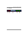
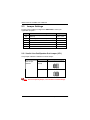
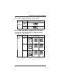
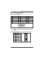
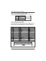
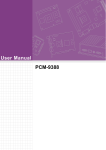
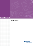
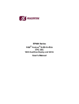
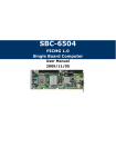
SBC81700 Series VIA V4 C7/Eden PICMG 1.0 Full-Size Single Board Computer User’s Manual Disclaimers This manual has been carefully checked and believed to contain accurate information. AXIOMTEK Co., Ltd. assumes no responsibility for any infringements of patents or any third party’s rights, and any liability arising from such use. AXIOMTEK does not warrant or assume any legal liability or responsibility for the accuracy, completeness or usefulness of any information in this document. AXIOMTEK does not make any commitment to update the information in this manual. AXIOMTEK reserves the right to change or revise this document and/or product at any time without notice. No part of this document may be reproduced, stored in a retrieval system, or transmitted, in any form or by any means, electronic, mechanical, photocopying, recording, or otherwise, without the prior written permission of AXIOMTEK Co., Ltd. CAUTION If you replace wrong batteries, it causes the danger of explosion. It is recommended by the manufacturer that you follow the manufacturer’s instructions to only replace the same or equivalent type of battery, and dispose of used ones. ©Copyright 2008 AXIOMTEK Co., Ltd. All Rights Reserved September 2008, Version A1 Printed in Taiwan ii ESD Precautions Computer boards have integrated circuits sensitive to static electricity. To prevent chipsets from electrostatic discharge damage, please take care of the following jobs with precautions: Do not remove boards or integrated circuits from their anti-static packaging until you are ready to install them. Before holding the board or integrated circuit, touch an unpainted portion of the system unit chassis for a few seconds. It discharges static electricity from your body. Wear a wrist-grounding strap, available from most electronic component stores, when handling boards and components. Trademarks Acknowledgments AXIOMTEK is a trademark of AXIOMTEK Co., Ltd. ® Windows is a trademark of Microsoft Corporation. Phoenix & AWARD are trademarks of Phoenix Technology Ltd. IBM, PC/AT, PS/2, VGA are trademarks of International Business Machines Corporation. VIA is a trademark of VIA Technologies, Inc. Winbond is a trademark of Winbond Electronics Corp. Realtek is a trademark of Realtek Semi-Conductor Co., Ltd. Other brand names and trademarks are the properties and registered brands of their respective owners. iii Table of Contents Disclaimers ........................................................................................................... ii ESD Precautions ................................................................................................. iii CHAPTER 1 INTRODUCTION ..................................................................................... 1 1.1 Specifications .......................................................................................... 2 1.2 Utilities Supported ................................................................................... 4 1.3 I/O Bracket .............................................................................................. 5 CHAPTER 2 JUMPERS AND CONNECTORS ............................................................ 6 2.1 Board Dimensions ................................................................................... 6 2.2 Board Layouts ......................................................................................... 7 2.3 Jumper Settings ...................................................................................... 8 2.3.1 Audio Line-Out/Speaker Out Jumper (JP1)...................................... 8 2.3.2 Power Suppy Selection Jumper (JP2).............................................. 9 2.3.3 COM2 Mode Select Jumpers (JP3, JP4, JP5) ................................. 9 2.3.4 CMOS Clear Jumper (JP6) ............................................................ 10 2.4 Connectors ............................................................................................ 11 2.4.1 Audio Connector (AUDIO1)............................................................ 12 2.4.2 Front Panel Connector (CN1)......................................................... 12 2.4.3 ACPI Connector (CN3)................................................................... 13 2.4.4 Serial Port Interface (CN5, CN7).................................................... 14 2.4.5 USB 1 ~4 Connectors (CN6, CN2)................................................. 14 2.4.6 LAN External LED Connectors (CN9, CN12) ................................. 15 2.4.7 Ethernet RJ-45 Connectors with LED (CN10, CN13)..................... 16 2.4.8 SATA Connector (CN11) ................................................................ 16 2.4.9 VGA Connector (CN15).................................................................. 17 2.4.10 Keyboard & Mouse External Connectors (CN16, CN17)................ 17 2.4.11 Fan Connectors (FAN1, FAN2) ...................................................... 18 2.4.12 FDD Connector (FDD1).................................................................. 18 2.4.13 IDE Connectors (IDE1, IDE2)......................................................... 19 2.4.14 Parallel Port (LPT1)........................................................................ 19 CHAPTER 3 HARDWARE DESCRIPTION................................................................ 21 3.1 Microprocessors .................................................................................... 21 3.2 BIOS...................................................................................................... 21 3.3 System Memory..................................................................................... 21 3.4 I/O Port Address Map ............................................................................ 22 CHAPTER 4 PHOENIX-AWARD BIOS UTILITY ....................................................... 23 4.1 Entering Setup....................................................................................... 23 4.2 Control Keys .......................................................................................... 24 4.3 Getting Help .......................................................................................... 24 4.4 The Main Menu...................................................................................... 25 4.5 Standard CMOS Setup Menu................................................................ 26 4.6 Advanced BIOS Features...................................................................... 29 4.7 Advanced Chipset Features .................................................................. 34 4.8 Integrated Peripherals ........................................................................... 39 4.9 Power Management Setup .................................................................... 44 iv 4.10 4.11 4.12 4.13 4.14 4.15 4.16 PnP/PCI Configuration Setup ................................................................ 48 PC Health Status ................................................................................... 50 Frequency/Voltage Control.................................................................... 51 Load Optimized Defaults ....................................................................... 52 Set Supervisor/User Password.............................................................. 53 Save & Exit Setup ................................................................................. 54 Exit Without Saving ............................................................................... 55 APPENDIX A WATCHDOG TIMER ........................................................................... 57 APPENDIX B PCI IRQ ROUTING .............................................................................. 59 v MEMO vi SBC81700 VIA V4 SBC User’s Manual CHAPTER 1 INTRODUCTION The SBC81700 PICMG 1.0 full-size Single Board Computer supports VIA V4 C7/Eden processors, at differential host clock of 400 MHz. The board integrates chipsets VIA CN700 + VT8237R-Plus and ITE8888G that deliver low power consumption and cost effective and stable legacy bus interfaces, multiple I/O functions for interactive applications and various embedded computing solutions. There are two 240-pin DDR2 DIMM sockets for dual channel DDR2 400/533, maximum memory capacity up to 2GB. The board also features Ethernet 10/100Mb, Dual PCI LAN, two-channel PATA-133 support up to four devices, two serial ATA-150 ports and built-in six USB 2.0 high speed compliant that can achieve the best stability and reliability for industrial applications. Introduction 1 SBC81700 VIA V4 SBC User’s Manual 1.1 Specifications CPU z VIA V4 C7/Eden processors System Chipset z VIA CN700 + VT8237R-Plus Front-Side Bus z Differential Host Clock of 400 MHz BIOS z Phoenix-Award PnP Flash BIOS System Memory z Two 240-pin DDR2 DIMM sockets Maximum up to 2GB DDR2 memory L2 Cache z Integrated in CPU Onboard Multi-I/O z Parallel Port -- 26-pin 2.54 pitch box-header with SPP/EPP/ECP supported Serial Port 10-pin 2.54 pitch box-header for RS-232 10-pin 2.54 pitch box-header for RS-232/422/485 with jumper selectable, RS-485 with auto-flow control Floppy controller –34-pin 2.54 pitch box-header to support two drives (1.44MB for each) USB Interface z Six USB ports compliant with USB Spec. Rev. 2.0 VGA Controller z Chipset Optimized Unified Memory Architecture (UMA) Supports 16 / 32 / 64 MB Frame Buffers size Graphics engine clocks up to 200 MHz decoupled 2 Introduction SBC81700 VIA V4 SBC User’s Manual from memory clock Internal AGP 8x performance Two 128-bit internal data paths between North Bridge and graphics core for frame buffer and texture/ command access PCI v2.2 Host Bus compliant AGP v3.5 compliant Memory Size -- Supports 16 / 32 / 64 MB Frame Buffers size Resolution -- Supports CRT resolutions up to 1600 x 1200 Analog Output Interface CRT display interface with 24-bit true-color RAMDAC up to 300 MHz pixel rate with gamma correction capability With 15-pin D-Sub connector on the rear I/O Ethernet z z The LAN1/LAN2: dual Realtek RTL8100C 10/100 Base-T Fast Ethernet controller Via PCI bus Wake-on-LAN support Serial ATA z Hardware Monitoring z z Built-in two SATA-150 ports Monitoring temperatures, voltages, and cooling fan status Watchdog Timer Reset supported 1~255 seconds; up to 255 levels Dimensions: 338 x 122 mm NOTE All specifications and images are subject to change without notice. Introduction 3 SBC81700 VIA V4 SBC User’s Manual 1.2 Utilities Supported Chipset Utility and Drivers VGA Drivers Ethernet Utility and Drivers z z z 4 Introduction SBC81700 VIA V4 SBC User’s Manual 1.3 USB1 I/O Bracket USB2 Introduction VGA Port LAN1 LAN2 5 SBC81700 VIA V4 SBC User’s Manual CHAPTER 2 JUMPERS AND CONNECTORS 2.1 6 Board Dimensions Jumpers and Connectors SBC81700 VIA V4 SBC User’s Manual 2.2 Board Layouts Component Side Jumpers and Connectors 7 SBC81700 VIA V4 SBC User’s Manual 2.3 Jumper Settings Proper jumper settings configure the SBC81700 to meet your application purpose. Jumper Default Setting Jumper Setting JP1 Audio Line Out/Speaker Out: Line out (Optional) Short 1-3, 2-4 JP2 Power Supply Selection: ATX power supply Short 2-3 JP3 COM2 Mode Select: RS-232 Short 1-2 JP4 JP5 COM2 Mode Select: RS-232 COM2 Mode Select: RS-232 Short 3-5, 4-6 Short 3-5, 4-6 JP6 Clear CMOS Setting: Normal Short 1-2 2.3.1 Audio Line-Out/Speaker Out Jumper (JP1) This jumper makes the selection of Audio output. Description Audio Output Selection Function Jumper Setting Line Out (Default) Speak Out Note This is an optional jumper, not mounted as a default design. 8 Jumpers and Connectors SBC81700 VIA V4 SBC User’s Manual 2.3.2 Power Suppy Selection Jumper (JP2) Description Function Power Supply Selection Jumper Setting ATX POWER (Default) AT POWER 2.3.3 COM2 Mode Select Jumpers (JP3, JP4, JP5) These jumpers select the COM2 port’s communication mode to operate RS-232 or RS-422/485. Description Function Jumper Setting JP3 JP4 JP5 RS-422 JP3 JP4 JP5 RS-485 JP3 JP4 JP5 COM2 Mode RS-232 Select (Default) Jumpers and Connectors 9 SBC81700 VIA V4 SBC User’s Manual 2.3.4 CMOS Clear Jumper (JP6) You may need to use this jumper is to clear the CMOS memory if incorrect BIOS settings. Description Function Jumper Setting CMOS Clear Normal (Default) Clear CMOS 10 Jumpers and Connectors SBC81700 VIA V4 SBC User’s Manual 2.4 Connectors Connectors connect the CPU card with other parts of the system. Loose or improper connection might cause problems. Make sure all connectors are properly and firmly connected. Here is a summary table shows you all connectors on the board. Connectors Audio Connector (optional) Label AUDIO1 Flat Panel Bezel Connector CN1 ACPI Connector CN3 Com1 Connector Com2 Connector CN5 CN7 USB1/2 Connector CN6 USB3/4 Connector CN2 LAN External LED Connectors CN9, CN12 LAN Connectors CN10, CN13 SATA Connector VGA Connector CN11 CN15 Keyboard External Connector CN16 Mouse External Connector CN17 USB5/6 Connectors FAN Power connectors DDRII DIMMs Floppy Connector IDE Connectors LPT Port Connector Jumpers and Connectors CN20, CN18 FAN1, FAN2 DIMM1, DIMM2 FDD1 IDE1, IDE2 LPT1 11 SBC81700 VIA V4 SBC User’s Manual 2.4.1 Audio Connector (AUDIO1) AUDIO1 is a 10-pin connector to support the audio interface. Note It is optional function by request. Pin 1 Signal MIC-IN Pin Signal 2 GND 3 Line In L 4 GND 5 Line In R 6 GND 7 Audio Out L 8 GND 9 Audio Out R 10 GND 2.4.2 Front Panel Connector (CN1) Power LED Pins 1, 3, 5 connect the system power LED indicator to the system power switch on the case. Pin 1 is assigned to +, and pin 5 to -. The Power LED lights up when the system is powered ON. External Speaker and Internal Buzzer Connector This 4-pin connector (Pin 2, 4, 6, 8) can be connected to the casemounted speaker unit or internal buzzer. While connecting the CPU card to an internal buzzer, please short pins 2-4; while connecting to an external speaker, you need to set pins 2-4 to Open and connect the speaker cable to pin 8 (+) and pin 2 (-). ATX Power On/Off Button This 2-pin connector (Pin 9, 10) connects the front panel’s ATX power button to the CPU card, which allows users to control ATX 12 Jumpers and Connectors SBC81700 VIA V4 SBC User’s Manual power supply to be power on/off. System Reset Switch This 2-pin connector (Pin 11, 12) can be connected to the casemounted reset switch that reboots your computer, not turns OFF the power switch. It is a better way to reboot your system for a longer life of the system’s power supply. HDD Activity LED This connection is linked to hard drive activity LED on the control panel. LED flashes when HDD is being accessed. The 2-pin connector (Pin 13, 14) connects the hard disk drive to the front panel HDD LED, Pin 13 assigned as -, and Pin 14 as +. 2.4.3 ACPI Connector (CN3) Advanced Configuration and Power Interface (ACPI) defines a flexible and extensible interface that allows system designers to select appropriate cost/feature trade-offs for power management. The interface enables and supports reliable power management through improved hardware and operating system coordination. The specification enables new power management technology to evolve independently in operating systems and hardware while ensuring that they continue to work together. CN3 is a 6-pin header connector that provides ACPI interface. Pin Signal 1 EXTSMI 2 GND 3 POWER BUTTON 4 GND 5 SUSB 6 +5VSB Jumpers and Connectors 1 2 3 4 5 6 13 SBC81700 VIA V4 SBC User’s Manual 2.4.4 Serial Port Interface (CN5, CN7) The serial interface for the board consists of COM1 port (CN5) and COM2 (CN7) to support RS-232/RS-422/RS-485. CN5 & CN7: The RS-232 pin assignment is listed on the following table. Pin 1 Signal Pin Data Carrier Detect (DCD) 2 Signal Data Set Ready (DSR) 3 Receive Data (RXD) 4 Request to Send (RTS) 5 Transmit Data (TXD) Data Terminal Ready (DTR) 6 Clear to Send (CTS) 8 Ring Indicator (RI) Ground (GND) 10 NC 7 9 CN7: The RS-422/485 pin assignment is listed on the following table. Pin # 1 2 3 4 5 6 7 8 9 10 2.4.5 Signal Name RS-422 TXNo connector TX+ No connector RX+ No connector RXNo connector GND No connector RS-485 DATANo connector DATA+ No connector No connector No connector No connector No connector GND No connector USB 1 ~4 Connectors (CN6, CN2) These Universal Serial Bus (USB) connectors on this board are for installing versatile USB interface peripherals. These are 10-pin standard USB connectors. 14 Jumpers and Connectors SBC81700 VIA V4 SBC User’s Manual Pin Signal Pin Signal 1 +5V 2 +5V 3 D0- 4 D1- 5 D0+ 6 D1+ 7 Ground (GND) 8 Ground (GND) 9 NC 10 Ground (GND) 1 10 2 2.4.6 LAN External LED Connectors (CN9, CN12) Pin Signal Pin Signal 1 LAN_ACT- 2 +3.3VSB 3 LAN_LINK- 4 LAN_LINK+ Jumpers and Connectors 15 SBC81700 VIA V4 SBC User’s Manual 2.4.7 Ethernet RJ-45 Connectors with LED (CN10, CN13) The RJ-45 connector CN10 and CN13 are for Ethernet. Pin Signal 1 Tx+ (Data transmission positive) 2 Tx- (Data transmission negative) 3 Rx+(Data reception positive) 4 RJ45 termination 5 RJ45 termination 6 Rx- (Data reception negative) 7 RJ45 termination 8 RJ45 termination A Active LED B 100 LAN LED 2.4.8 SATA Connector (CN11) This SATA connector is for high-speed SATA interface ports and it can be connected to hard disk devices. Pin 16 Signal 1 GND 2 SATA_TX+ 3 SATA_TX- 4 GND 5 RX- 6 RX+ 7 GND Jumpers and Connectors SBC81700 VIA V4 SBC User’s Manual 2.4.9 VGA Connector (CN15) The VGA connector CN15 is a standard 15-pin connector commonly used for the CRT VGA display. Pin Signal Pin Signal Pin Signal 1 Red 2 Green 3 Blue 4 N.C 5 AGND 6 AGND 7 AGND 8 AGND 9 +5V 10 AGND 11 N.C 12 DDC DATA 13 Horizontal Sync 14 Vertical Sync 15 DDC CLK 2.4.10 Keyboard & Mouse External Connectors (CN16, CN17) The board provides the Keyboard and Mouse interface with two 5-pin connectors CN16 and CN17. Pin Signal 1 Clock 2 Data 3 N.C 4 GND 5 Power 1 2 3 Jumpers and Connectors 4 5 17 SBC81700 VIA V4 SBC User’s Manual 2.4.11 Fan Connectors (FAN1, FAN2) A CPU fan is always needed for cooling CPU heat. FAN1 is a fan connector for the system, and FAN2 for CPU. Pin Signal 1 Ground 2 +12V 3 Sensor 2.4.12 FDD Connector (FDD1) The board provides a 34-pin header type connector, FDD1, supporting up to two floppy drives. The floppy drives may be any one of the following types: 5.25" 360KB/1.2MB and 3.5" 720KB/1.44MB/2.88MB. Pin Signal Pin Signal Pin 1 GND 2 Reduce write current 3 GND 4 N/C 5 GND 6 N/C 7 GND 8 Index # 9 GND Signal 10 Motor enable A # 11 GND 12 Drive select B # 13 GND 14 Drive select A # 15 GND 16 Motor enable B # 17 GND 18 Direction # 19 GND 20 STEP # 21 GND 22 Write data # 23 GND 24 Write gate # 25 GND 26 Track 0 # 27 GND 28 Write protect # 29 GND 30 Read data # 31 GND 32 Side 1 select # 33 GND 34 Disk change # 18 Jumpers and Connectors SBC81700 VIA V4 SBC User’s Manual 2.4.13 IDE Connectors (IDE1, IDE2) Pin Signal Pin Signal Pin Signal 1 Reset # 2 GND 3 Data 7 4 Data 8 5 Data 6 6 Data 9 7 10 Data 5 Data 11 8 11 Data 10 Data 3 9 12 Data 4 Data 12 13 Data 2 14 Data 13 15 Data 1 16 Data 14 17 Data 0 18 Data 15 19 GND 20 N.C 21 N.C 22 25 GND IOR # 23 26 IOW # GND 24 27 GND IOCHRDY 28 N.C 29 N.C 30 GND-Default 31 Interrupt 32 N.C 33 SA1 34 N.C 35 SA0 36 SA2 37 40 HDC CS0 # GND 38 HDC CSI # 39 HDD Active # 2.4.14 Parallel Port (LPT1) There is a multi-mode parallel port LPT1 that supports the following modes: 1. Standard mode: IBM PC/XT, PC/AT and PS/2™ compatible with bi-directional parallel port 2. Enhanced mode: Enhance parallel port (EPP) compatible with EPP 1.7 and EPP 1.9 (IEEE 1284 compliant) 3. High speed mode: Microsoft and Hewlett Packard extended capabilities port (ECP) IEEE 1284 compliant Jumpers and Connectors 19 SBC81700 VIA V4 SBC User’s Manual Pin Signal Pin Signal 1 Strobe# 2 Auto Form Feed# 3 Data 0 4 Error# 5 Data 1 6 Initialize# 7 Data 2 8 Printer Select In# 9 Data 3 10 GND 11 Data 4 12 GND 13 Data 5 14 GND 15 Data 6 16 GND 17 Data 7 18 GND 19 Acknowledge# 20 GND 21 Busy 22 GND 23 Paper Empty# 24 GND 25 Printer Select 26 NC 20 Jumpers and Connectors SBC81700 VIA V4 SBC User’s Manual CHAPTER 3 HARDWARE DESCRIPTION 3.1 Microprocessors The SBC81700 Series supports VIA V4 C7/Eden processors, which ® make your system operated under Windows XP and Linux environments. The system performance depends on the microprocessor. Make sure your installed microprocessor with all correct settings that prevent the CPU from damages. 3.2 BIOS The SBC81700 Series uses Phoenix-Award Plug and Play BIOS with a single 4Mbit Flash. 3.3 System Memory The SBC81700 Series industrial CPU card supports two 240-pin DDR2 DIMM sockets for a maximum memory of 2GB DDR2 SDRAMs. The memory module can come in sizes of 64 MB, 128 MB, 256 MB, 512 MB, 1 GB and 2 GB. Hardware Description 21 SBC81700 VIA V4 SBC User’s Manual 3.4 I/O Port Address Map The VIA V4 C7/Eden CPUs can communicate via I/O ports. There are total 1KB port addresses available for assignment to other devices via I/O expansion cards. Address 22 Devices 000-01F DMA controller #1 020-03F Interrupt controller #1 040-05F Timer 060-06F Keyboard controller 070-07F Real time clock, NMI 080-09F DMA page register 0A0-0BF Interrupt controller #2 0C0-0DF DMA controller #2 0F0 Clear math coprocessor busy signal 0F1 Reset math coprocessor 0F8-0FF Math processor 1F0-1F8 Fixed disk controller 250-25F HR I/O 300-31F Prototype card 380-38F SDLC #2 3A0-3AF SDLC #1 3B0-3BF MDA video card (including LPT1) 3C0-3CF EGA card 3D0-3DF CGA card 3F8-3FF Serial port #1 (COM1) 3E8-3EF Serial port #3 (COM3) 2F8-2FF Serial port #2 (COM2) 2E8-2EF Serial port #4 (COM4) 3F0-3FF Super I/O Hardware Description SBC81700 VIA V4 SBC User’s Manual CHAPTER 4 PHOENIX-AWARD BIOS UTILITY The Phoenix-Award BIOS provides users with a built-in Setup program to modify basic system configuration. All configured parameters are stored in a battery-backed-up RAM (CMOS RAM) to save the Setup information whenever the power is turned off. 4.1 Entering Setup There are two ways to enter the Setup program. You may either turn ON the computer and press <Del> immediately, or press the <Del> and/or <Ctrl>, <Alt>, and <Esc> keys simultaneously when the following message appears at the bottom of the screen during POST (Power on Self Test). TO ENTER SETUP PRESS DEL KEY If the message disappears before you respond and you still want to enter Setup, please restart the system to try it again. Turning the system power OFF and ON, pressing the “RESET” button on the system case or simultaneously pressing <Ctrl>, <Alt>, and <Del> keys can restart the system. If you do not press keys at the right time and the system doesn’t boot, an error message will pop out to prompt you the following information: PRESS <F1> TO CONTINUE, <CTRL-ALT-ESC> OR <DEL> TO ENTER SETUP Phoenix-Award BIOS Utility 23 SBC81700 VIA V4 SBC User’s Manual 4.2 Control Keys Up arrow Move cursor to the previous item Down arrow Move cursor to the next item Left arrow Move cursor to the item on the left hand Right arrow Move to the item in the right hand Esc key PgUp/“+” key Main Menu -- Quit and delete changes into CMOS Status Page Setup Menu and Option Page Setup Menu -- Exit current page and return to Main Menu Increase the numeric value or make changes PgDn/“−“ key Decrease the numeric value or make changes F3 key General help, only for Status Page Setup Menu and Option Page Setup Menu Change color from total 16 colors. F2 to select color forward, (Shift) F2 to select color backward Reserved F4 key Reserved F1 key (Shift) F2 key F8 key Restore the previous CMOS value from CMOS, only for Option Page Setup Menu Load the default CMOS value from BIOS default table, only for Option Page Setup Menu Load the Setup default, only for Option Page Setup Menu Reserved F9 key Reserved F10 key Save all the CMOS changes, only for Main Menu F5 key F6 key F7 key 4.3 Getting Help z Main Menu The online description of the highlighted setup function is displayed at the bottom of the screen. z Status Page Setup Menu/Option Page Setup Menu Press <F1> to pop out a small Help window that provides the description of using appropriate keys and possible selections for highlighted items. Press <F1> or <Esc> to exit the Help Window. 24 Phoenix-Award BIOS Utility SBC81700 VIA V4 SBC User’s Manual 4.4 The Main Menu Once you enter the Award BIOS CMOS Setup Utility, the Main Menu appears on the screen. In the Main Menu, there are several Setup functions and a couple of Exit options for your selection. Use arrow keys to select the Setup Page you intend to configure then press <Enter> to accept or enter its sub-menu. NOTE If your computer can not boot after making and saving system changes with Setup, the Award BIOS will reset your system to the CMOS default settings via its built-in override feature. It is strongly recommended that you should avoid changing the chipset’s defaults. Both Award and your system manufacturer have carefully set up these defaults that provide the best performance and reliability. Phoenix-Award BIOS Utility 25 SBC81700 VIA V4 SBC User’s Manual 4.5 Standard CMOS Setup Menu The Standard CMOS Setup Menu displays basic information about your system. Use arrow keys to highlight each item, and use <PgUp> or <PgDn> key to select the value you want in each item. z z Date The date format is <day>, <date> <month> <year>. Press <F3> to show the calendar. day It is determined by the BIOS and read only, from Sunday to Saturday. date It can be keyed with the numerical/ function key, from 1 to 31. month It is from January to December. year It shows the current year of BIOS. Time This item shows current time of your system with the format <hour> <minute> <second>. The time is calculated based on the 24-hour military-time clock. For example, 1 p.m. is 13:00:00. 26 Phoenix-Award BIOS Utility SBC81700 VIA V4 SBC User’s Manual z IDE Primary Master/Primary Slave The categories identify the types of one channel that have been installed in the computer. There are 45 predefined types and 2 users definable types are for Enhanced IDE BIOS. Type 1 to Type 45 is predefined. Type User is user-definable. Press <PgUp>/<+> or <PgDn>/<−> to select a numbered hard disk type or type the number and press <Enter>. Note that the specifications of your drive must match with the drive table. The hard disk will not work properly if you enter improper information within this category. If your hard disk drive type does not match or is not listed, you can use Type User to define your own drive type manually. If you select Type User, related information is asked to be entered to the following items. Enter the information directly from the keyboard and press <Enter>. This information should be provided in the documentation from your hard disk vendor or the system manufacturer. If the controller of HDD interface is ESDI, select “Type 1”. If the controller of HDD interface is SCSI, select “None”. If the controller of HDD interface is CD-ROM, select “None”. CYLS. number of cylinders LANDZONE landing zone HEADS number of heads SECTORS number of sectors PRECOMP write precom MODE HDD access mode If there is no hard disk drive installed, select NONE and press <Enter>. z z Dive A type The item identifies the types of floppy disk installed in the computer. None No floppy drive installed 360K, 3.5 in 1.2M, 3.5 in 3.5 inch PC-type standard drive; 360Kb Mini ITXcity 3.5 inch AT-type high-density drive; 1.2MB Mini ITXcity 720K, 3.5 in 3.5 inch double-sided drive; 720Kb Mini ITXcity 1.44M, 3.5 in 2.88M, 3.5 in 3.5 inch double-sided drive; 1.44MB Mini ITXcity 3.5 inch double-sided drive; 2.88MB Mini ITXcity Video Select the display adapter type for your system. Phoenix-Award BIOS Utility 27 SBC81700 VIA V4 SBC User’s Manual z Halt On This field determines whether the system will halt if an error is detected during power up. No errors The system boot will halt on any error detected. (default) All errors Whenever the BIOS detect a non-fatal error, the system will stop and you will be prompted. All, But Keyboard The system boot will not stop for a keyboard error; it will stop for all other errors. All, But Diskette The system boot will not stop for a disk error; it will stop for all other errors. All, But Disk/Key The system boot will not stop for a keyboard or disk error; it will stop for all other errors. Press <Esc> to return to the Main Menu page. 28 Phoenix-Award BIOS Utility SBC81700 VIA V4 SBC User’s Manual 4.6 Advanced BIOS Features This section allows you to configure and improve your system, to set up some system features according to your preference. Phoenix-Award BIOS Utility 29 SBC81700 VIA V4 SBC User’s Manual z Hard Disk Boot Priority Scroll to this item and press <Enter> to view the sub menu to decide the disk boot priority. Press <Esc> to return to the Advanced BIOS Features page. z Virus Warning This option flashes on the screen. During and after the system boot up, any attempt to write to the boot sector or partition table of the hard disk drive will halt the system with the following message. You can run an anti-virus program to locate the problem. The default setting is “Disabled”. ! WARNING ! Disk boot sector is to be modified Type “Y” to accept write or “N” to abort write Award Software, Inc. Enabled 30 Activates automatically when the system boots up causing a warning message to appear when there is an attempt to access the boot sector or hard disk partition table. Phoenix-Award BIOS Utility SBC81700 VIA V4 SBC User’s Manual Disabled No warning message will appear when attempts to access the boot sector or hard disk partition table are made. NOTE This function is only available with DOS and other operating systems that do not trap INT13. z CPU Internal Cache This option speeds up memory access. However, it depends on the CPU/chipset design. The default setting is “Enabled”. The “CPU Internal Cache” item won’t appear on the menu, when CPU doesn’t have a built-in internal cache. Enabled Enable cache Disabled Disable cache z CPU L2 Cache ECC Checking When enabled, this allows ECC checking of the CPU’s L2 cache. By default, this field is “Enabled”. z Quick Power On Self Test This option speeds up Power on Self Test (POST) after you turn on the system power. If set as Enabled, BIOS will shorten or skip some check items during POST. The default setting is “Enabled”. Enabled Enable Quick POST Disabled Normal POST z First/Second/Third Boot Device These items allow the selection of the 1st, 2nd, and 3rd devices that the system will search for during its boot-up sequence. The wide range of selection includes Floppy, LS120, ZIP100, HDD0~3, SCSI, and CDROM. z Boot Other Device This item allows the user to enable/disable the boot device not listed on the First/Second/Third boot devices option above. The default setting is “Enabled”. Phoenix-Award BIOS Utility 31 SBC81700 VIA V4 SBC User’s Manual z Onboard Lan Boot ROM This item allows you to decide to boot from whether LAN1 or LAN2. The options available are “LAN1“, “LAN2“, and “Disabled“. z Boot Up Floppy Seek During POST, BIOS will determine the floppy disk drive type, 40 or 80 tracks. 360Kb type is 40 tracks while 720Kb, 1.2MB and 1.44MB are all 80 tracks. The default value is “Enabled”. Enabled BIOS searches for floppy disk drive to determine if it is 40 or 80 tracks. Note that BIOS can not tell from 720K, 1.2M or 1.44M drives type as they are all 80 tracks. Disabled BIOS will not search for the type of floppy disk drive by track number. There will be no warning message displayed if the drive installed is 360K. z Boot Up NumLock Status Selects power on state for NumLock. The default value is “On”. z Typematic Rate Setting This determines the typematic rate of the keyboard. The default value is “Disabled”. z Enabled Enable typematic rate and typematic delay programming Disabled Disable typematic rate and typematic delay programming. The system BIOS will use default value of these 2 items and the default is controlled by keyboard. Typematic Rate (Chars/Sec) This option refers to the number of characters the keyboard can type per second. The default value is “6”. 32 6 6 characters per second 8 8 characters per second 10 10 characters per second 12 12 characters per second 15 20 15 characters per second 20 characters per second 24 24 characters per second 30 30 characters per second Phoenix-Award BIOS Utility SBC81700 VIA V4 SBC User’s Manual z z Typematic Delay (Msec) This option sets the display time interval from the first to the second character when holding a key. The default value is “250”. 250 250 msec 500 500 msec 750 1000 750 msec 1000 msec Security Option This item allows you to limit access to the system and Setup, or just to Setup. The default value is “Setup”. System The system will not boot and access to Setup will be denied if the incorrect password is entered at the prompt. Setup The system will boot, but access to Setup will be denied if the correct password is not entered at the prompt. NOTE To disable security, select PASSWORD SETTING at Main Menu and then you will be asked to enter password. Do not type anything, just press <Enter> and it will disable security. Once the security is disabled, the system will boot and you can enter Setup freely. z MPS Version Control For OS This item specifies the version of the Multiprocessor Specification (MPS). Version 1.4 has extended configuration tables to improve support for multiple PCI bus configurations and provide future expandability. z Video BIOS Shadow Enable this parameter to turn on BIOS ROM shadowing for the block of memory normally used for standard VGA video ROM code. z Small Logo (EPA) Show If enabled, the EPA logo will appear during system booting up; if disabled, the EPA logo will not appear. Press <Esc> to return to the Main Menu page. Phoenix-Award BIOS Utility 33 SBC81700 VIA V4 SBC User’s Manual 4.7 Advanced Chipset Features Since the features in this section are related to the chipset on the CPU board and are completely optimized, you are not recommended to change the default settings in this setup table unless you are well oriented with the chipset features. 34 Phoenix-Award BIOS Utility SBC81700 VIA V4 SBC User’s Manual z DRAM Clock/Drive Control Scroll to this item and press <Enter> to view the sub menu DRAM Clock/Drive Control. ¾ ¾ ¾ ¾ ¾ Current FSB/DRAM Frequency Those two items are read-only to show the current FSB and DRAM. DRAM Clock Use this item to adjust memory speed. Option By SPD (Serial Detect Presence) makes it possible to do an automatic selection. DRAM Timing Use this item to increase the timing of the memory. This is related to the cooling of memory. SDRAM CAS Latency When synchronous DRAM is installed, the DRAM timing determines the CAS latency’s clock cycles. It is strongly recommended to keep this item at default value specified by the system designer. Bank Interleave Select 2-Bank or 4-Bank interleave for 64-Mb SDRAM. Phoenix-Award BIOS Utility 35 SBC81700 VIA V4 SBC User’s Manual ¾ ¾ ¾ ¾ ¾ Read to Precharge (Trtp) Use this item to adjust time interval between a read and a precharge command. Write to CMD (Twtr) The default time setting is 1T/2T. Write Recovery Time (Twr) Use this item to specify the time (in cycles of clock) necessarily inserted between the operation of valid writing memory and a cooling report. DRAM Command Rate Use this item to manually define the chipset-to-memory latency values. RDSAIT Mode This item is to select the RDSAIT mode auto or manual. Press <Esc> to return to the Advanced Chipset Features page. 36 Phoenix-Award BIOS Utility SBC81700 VIA V4 SBC User’s Manual z AGP & P2P Bridge Control Use this item to set AGP and P2P Bridge controls for allocating system RAM amount to AGP for video purposes. Scroll to this item and press <Enter> to view the sub menu AGP & P2P Bridge Control. ¾ ¾ ¾ ¾ ¾ AGP Aperture Size This item controls the memory space allocation to AGP for display. The aperture is a portion of the PCI memory address range dedicated to graphics memory address space. AGP 2.0 Mode This item decides the AGP Mode of the integrated graphics. AGP Master 1 WS Write When this item is enabled, the write to the AGP (Accelerated Graphics Port) will be executed with one wait state. AGP Master 1 WS Read When this item is enabled, the read to the AGP (Accelerated Graphics Port) will be executed with one wait state. VGA Share Memory Size This item controls the amount of the system memory allocated to the integrated graphics processor when the system boots up. Press <Esc> to return to the Advanced Chipset Features page. Phoenix-Award BIOS Utility 37 SBC81700 VIA V4 SBC User’s Manual z CPU & PCI Bus Control Use this item to enable the immediate Write to PCI Bus, or disable it for a later execution. Scroll to this item and press <Enter> to view the sub menu CPU & PCI Bus Control. ¾ ¾ PCI Master 0 WS Write When this item is enabled, the writes to the PCI bus will be executed with zero wait state. PCI Delay Transaction The chipset has an embedded 32-bit posted write buffer to support delay transactions cycles. Select “Enabled” to support compliance with PCI specification version 2.1. Press <Esc> to return to the Advanced Chipset Features page. z System BIOS Cacheable Use this item to enable or disable the system BIOS cache. z Video RAM Cacheable Use this item to enable or disable the video RAM cache. 38 Phoenix-Award BIOS Utility SBC81700 VIA V4 SBC User’s Manual z Init Display First This item allows you to decide whether PCI Slot or AGP to be the first primary display card. Press <Esc> to return to the Main Menu page. 4.8 Integrated Peripherals This section allows you to configure your SuperIO Device, IDE Function and Onboard Device. Phoenix-Award BIOS Utility 39 SBC81700 VIA V4 SBC User’s Manual z VIA OnChip IDE Device Scroll to this item and press <Enter> to view the sub menu VIA OnChip IDE Device. ¾ ¾ ¾ ¾ ¾ 40 OnChip SATA Enable this item to set the SATA channel to IDE Mode. IDE DMA transfer access Automatic data transfer between system memory and IDE device with minimum CPU intervention. This improves data throughput and frees CPU to perform other tasks. OnChip IDE Channel 0/1 The board supports two channel of ordinary IDE interface. Select “Enabled” to activate each channel separately. IDE Prefetch Mode Selecting “Enabled” reduces latency between each drive read/write cycle, but may cause instability in IDE subsystems that cannot support such fast performance. If you are getting disk drive errors, try setting this value to Disabled. This field does not appear when the Internal PCI/IDE field, above, is Disabled. IDE Master/Slave PIO The four IDE PIO (Programmed Input/Output) fields let you set a PIO mode (0-4) for each of the four IDE devices that Phoenix-Award BIOS Utility SBC81700 VIA V4 SBC User’s Manual ¾ ¾ the onboard IDE interface supports. Modes 0 to 4 provide successively increased performance. In Auto mode, the system automatically determines the best mode for each device. IDE Master/Slave UDMA Select the mode of operation for the IDE drive. Ultra DMA33/66/100/133 implementation is possible only if your IDE hard drive supports it and the operating environment includes a DMA driver. If your hard drive and your system software both support Ultra DMA-33/66/100/133, select Auto to enable UDMA mode by BIOS. IDE HDD Block Mode Block mode is also called block transfer, multiple commands, or multiple sectors read/write. If your IDE hard drive supports block mode (most new drives do), select Enabled for automatic detection of the optimal number of block read/writes per sector the drive can support. Press <Esc> to return to the Integrated Peripherals page. Phoenix-Award BIOS Utility 41 SBC81700 VIA V4 SBC User’s Manual z VIA OnChip PCI Device Scroll to this item and press <Enter> to view the sub menu VIA OnChip PCI Device. ¾ ¾ ¾ ¾ ¾ ¾ VIA-3058 AC97 Audio Set this item Auto to enable VIA-3058 AC97 Audio chipset. OnChip USB Controller Enable this item if you are using the USB in the system. You should disable this item if a higher-level controller is added. OnChip EHCI Controller Enable this item if you are using the EHCI (USB2.0) controller in the system. USB Emulation Enable this item to boot the hard drive by a USB device. USB Keyboard Support Enable this item if the system has a Universal Serial Bus (USB) controller, and you have a USB keyboard. USB Mouse Support Enable this item to boot the hard drive by a USB mouse. Press <Esc> to return to the Integrated Peripherals page. 42 Phoenix-Award BIOS Utility SBC81700 VIA V4 SBC User’s Manual z Super IO Device Scroll to this item and press <Enter> to view the sub menu Super IO Device. ¾ ¾ ¾ ¾ Onboard FDC Controller Select Enabled if your system has a floppy disk controller (FDC) installed on the system board and you wish to use it. If you install and-in FDC or the system has no floppy drive, select Disabled in this field. The options available are Enabled, Disabled. Onboard Serial Port 1 / 2 Select an address and corresponding interrupt for the serial port. Options: 3F8/IRQ4, 2E8/IRQ3, 3E8/IRQ4, 2F8/IRQ3, Disabled, Auto. Onboard Parallel Port This item allows you to determine access onboard parallel port controller with which I/O address. The options available are 378H/IRQ7, 278H/IRQ5, 3BC/IRQ7, Disabled. Parallel Port Mode Select an operating mode for the onboard parallel (printer) port. Select Normal unless your hardware and software require one of the other modes offered in this field. The options available are EPP1.9, ECP, SPP, ECPEPP1.7, and EPP1.7. Phoenix-Award BIOS Utility 43 SBC81700 VIA V4 SBC User’s Manual ¾ ¾ EPP Mode Select Select EPP port type 1.7 or 1.9. ECP Mode Use DMA Select a DMA channel for the parallel port for use during ECP mode. Press <Esc> twice to return to the Main Menu. 4.9 Power Management Setup The Power Management Setup allows you to save energy of your system effectively. It will shut down the hard disk and turn OFF video display after a period of inactivity. z ACPI Function This item allows you to enable/disable the Advanced Configuration and Power Management (ACPI). The function is always Enabled. 44 Phoenix-Award BIOS Utility SBC81700 VIA V4 SBC User’s Manual z ACPI Suspend Type This item specifies the power saving modes for ACPI function. If your operating system supports ACPI, such as Windows 98SE, Windows ME and Windows 2000, you can choose to enter the Standby mode in S1 (POS) or S3 (STR) fashion through the setting of this field. Options are: [S1(POS)] The S1 sleep mode is a low power state. In this state, no system context is lost (CPU or chipset) and hardware maintains all system contexts. [S3(STR)] The S3 sleep mode is a lower power state where the information of system configuration and open applications/files is saved to main memory that remains powered while most other hardware components turn off to save energy. The information stored in memory will be used to restore the system when a “wake up” event occurs. z Power Management This option allows you to select the type of power Management. The options available are APM, ACPI. z HDD Power Down If HDD activity is not detected for the length of time specified in this field, the hard disk drive will be powered down while all other devices remain active. z Suspend Mode After the selected period of system inactivity (1 minute to 1 hour), all devices except the CPU shut off. The default value is “Disabled”. z Disabled System will never enter SUSPEND mode 1/2/4/6/8/10/2 0/30/40 Min/1 Hr Defines the continuous idle time before the system entering SUSPEND mode. If any item defined in (J) is enabled & active, SUSPEND timer will be reloaded Video Off Option This setting is used to control the mode in which the monitor will shut down. Setting options are: Always On Monitor remains on during power-saving modes. Suspend Æ Off Monitor blanked when system enters Suspend mode. Susp, StbyÆ Off Monitor blanked when system enters either Suspend or Standby mode. Phoenix-Award BIOS Utility 45 SBC81700 VIA V4 SBC User’s Manual All Modes Æ Off Monitor blanked when system enters any power saving. z Video Off Method This setting determines the manner in which the monitor is blanked. z Soft-Off by PWRBTN This option only works with systems using an ATX power supply. It also allows the user to define which type of soft power OFF sequence the system will follow. The default value is “Instant-Off”. Instant-Off Delay 4 Sec. z This option follows the conventional manner systems perform when power is turned OFF. Instant-Off is a soft power OFF sequence requiring only the switching of the power supply button to OFF Upon turning OFF system from the power switch, this option will delay the complete system power OFF sequence by approximately 4 seconds. Within this delay period, system will temporarily enter into Suspend Mode enabling you to restart the system at once. Ac Loss Auto Restart This setting specifies whether your system will reboot after a power failure or interrupt occurs. Available settings are: Off Leaves the computer in the power off state. On Leaves the computer in the power on state. Former-sts Restores the system to the status before power failure or interrupt occurred. 46 Phoenix-Award BIOS Utility SBC81700 VIA V4 SBC User’s Manual z IRQ/Event Activity Detect Scroll to this item and press <Enter> to view the sub menu IRQ/Event Activity Detect. Press <Esc> twice to return to the Main Menu page. Phoenix-Award BIOS Utility 47 SBC81700 VIA V4 SBC User’s Manual 4.10 PnP/PCI Configuration Setup This section describes configuring the PCI bus system. PCI, or Personal Computer Interconnect, is a system which allows I/O devices to operate at speeds nearing the speed the CPU itself uses when communicating with its own special components. This section covers some very technical items and it is strongly recommended that only experienced users should make any changes to the default settings. z PNP OS Installed Select Yes if the system operating environment is Plug-and-Play aware (e.g., Windows 95). The default value is “No”. z Reset Configuration Data Normally, you leave this field Disabled. Select Enabled to reset Extended System Configuration Data (ESCD) when you exit Setup or if you have installed a new add-on and the system reconfiguration has caused such a serious conflict that the operating system can not boot. The options available are Enabled and Disabled. z Resources Controlled By The Award Plug and Play BIOS can automatically configure all the 48 Phoenix-Award BIOS Utility SBC81700 VIA V4 SBC User’s Manual boot and Plug and Play-compatible devices. If you select Auto, all the interrupt request (IRQ), DMA assignment, and Used DMA fields disappear, as the BIOS automatically assigns them. The default value is “Manual”. z IRQ Resources When resources are controlled manually, assign each system interrupt as one of the following types, depending on the type of device using the interrupt: 1. Legacy ISA Devices compliant with the original PC AT bus specification, requiring a specific interrupt (such as IRQ4 for serial port 1). 2. PCI/ISA PnP Devices compliant with the Plug and Play standard, whether designed for PCI or ISA bus architecture. The default value is “PCI/ISA PnP”. z DMA Resources When resources are controlled manually, assign each system DMA channel as one of the following types, depending on the type of device using the interrupt: 1. 2. Legacy ISA Devices compliant with the original PC AT bus specification, requiring a specific DMA channel. PCI/ISA PnP Devices compliant with the Plug and Play standard, whether designed for PCI or ISA bus architecture. The default value is “PCI/ISA PnP”. z PCI/VGA Palette Snoop Some non-standard VGA display cards may not show colors properly. This field allows you to set whether MPEG ISA/VESA VGA Cards can work with PCI/VGA or not. When enabled, a PCI/VGA can work with a MPEG ISA/VESA VGA card. When disabled, a PCI/VGA cannot work with a MPEG ISA/VESA Card. z Assign IRQ For VGA The Enabled item allows the BIOS to auto-route an IRQ for use by a VGA card. z Assign IRQ For USB It enables or disables IRQ allocation for the USB (Universal Serial Bus). Enable this if you are using a USB device. Press <ESC> to return to the Main Menu page. Phoenix-Award BIOS Utility 49 SBC81700 VIA V4 SBC User’s Manual 4.11 PC Health Status This section supports hardware monitoring that lets you monitor those parameters for critical voltages, temperatures and fan speed of the board. z Current CPU Temperature These read-only fields reflect the functions of the hardware thermal sensor that monitors the chip blocks and system temperatures to ensure the system is stable. z Current SYSTEM Temperature Show you the current system1 temperature. z Current CPU FAN Speed These optional and read-only items show current speeds in RPM (Revolution Per Minute) for the CPU fan and chassis fan as monitored by the hardware monitoring IC. Press <ESC> to return to the Main Menu page. 50 Phoenix-Award BIOS Utility SBC81700 VIA V4 SBC User’s Manual 4.12 Frequency/Voltage Control This section is to control the CPU frequency and Supply Voltage, DIMM OverVoltage and AGP voltage. z CPU Clock Ratio Use this item to select a multiplier to set the CPU frequency. z Auto Detect PCI Clk The enabled item can automatically disable the clock source for a PCI slot which does not have a module in it, reducing EMI (ElectroMagnetic Interference). z Spread Spectrum If spread spectrum is enabled, EMI (ElectroMagnetic Interference) generated by the system can be significantly reduced. Press <ESC> to return to the Main Menu page. Phoenix-Award BIOS Utility 51 SBC81700 VIA V4 SBC User’s Manual 4.13 Load Optimized Defaults This option allows you to load the default values to your system configuration. These default settings are optimal and enable all high performance features. To load SETUP defaults value to CMOS SRAM, enter “Y”. If not, enter “N”. 52 Phoenix-Award BIOS Utility SBC81700 VIA V4 SBC User’s Manual 4.14 Set Supervisor/User Password You can set a supervisor or user password, or both of them. The differences between them are: 1. 2. Supervisor password: You can enter and change the options on the setup menu. User password: You can just enter, but have no right to change the options on the setup menu. When you select this function, the following message will appear at the center of the screen to assist you in creating a password. ENTER PASSWORD Type a maximum eight-character password, and press <Enter>. This typed password will clear previously entered password from the CMOS memory. You will be asked to confirm this password. Type this password again and press <Enter>. You may also press <Esc> to abort this selection and not enter a password. To disable the password, just press <Enter> when you are prompted to enter a password. A message will confirm the password is getting disabled. Once the password is disabled, the system will boot and you can enter Setup freely. PASSWORD DISABLED When a password is enabled, you have to type it every time you enter the Setup. It prevents any unauthorized persons from changing your system configuration. Additionally, when a password is enabled, you can also require the BIOS to request a password every time the system reboots. This would prevent unauthorized use of your computer. You decide when the password is required for the BIOS Features Setup Menu and its Security option. If the Security option is set to “System”, the password is required during booting up and entry into the Setup; if it is set as “Setup”, a prompt will only appear before entering the Setup. Phoenix-Award BIOS Utility 53 SBC81700 VIA V4 SBC User’s Manual 4.15 Save & Exit Setup This allows you to determine whether or not to accept the modifications. Typing “Y” quits the setup utility and saves all changes into the CMOS memory. Typing “N” brigs you back to Setup utility. 54 Phoenix-Award BIOS Utility SBC81700 VIA V4 SBC User’s Manual 4.16 Exit Without Saving Select this option to exit the Setup utility without saving the changes you have made in this session. Typing “Y” will quit the Setup utility without saving the modifications. Typing “N” will return you to Setup utility. Phoenix-Award BIOS Utility 55 SBC81700 VIA V4 SBC User’s Manual MEMO 56 Phoenix-Award BIOS Utility SBC81700 VIA V4 SBC User’s Manual APPENDIX A WATCHDOG TIMER Watchdog Timer Setting After the system stops working for a while, it can be auto-reset by the Watchdog Timer. The integrated Watchdog Timer can be set up in the system reset mode by program. z Timeout Value Range 1 to 255 Second z Program Sample Watchdog Timer can be set to system reset after 5-second timeout. 2E, 87 2E, 87 2E, 07 2F, 08 Logical Device 8 2E, 29 Set WDT Function Enable 2F, 20 2E, 30 Activate WDT 2F, 01 2E, F4 Set Value 2F, 05 Set 5 second of timeout Watchdog Timer 57 SBC81700 VIA V4 SBC User’s Manual Watchdog Timer Start ↓ Un-Lock WDT: O 2E 87; Un-lock super I/O O 2E 87; Un-lock super I/O ↓ Select Logic device: O 2E 07 O 2F 08 ↓ Set WDT Function: O 2E 29 O 2F 20 ↓ Activate WDT: ↓ Set base timer: ↓ WDT counting ↓ Re-set timer: ↓ IF No re-set timer IF to disable WDT 58 O 2E 30 O 2F 01 O 2E F4 O 2F M; M=00, 01, 02…FF (Hex), Value=0 to 255 O 2E F4 O 2F M; M=00, 01, 02…FF : WDT time-out, generate RESET O 2E 30 O 2F 00; Can be disable at any time Watchdog Timer SBC81700 VIA V4 SBC User’s Manual APPENDIX B PCI IRQ ROUTING PICMG PCI IRQ Routing Device ID Slot Int PCI Slot 0 31 0 BCDA PCI Slot 1 30 1 CDAB PCI Slot 2 PCI Slot 3 29 NC 2 NC DABC NC PCI IRQ Routing 59 SBC81700 VIA V4 SBC User’s Manual MEMO 60 PCI IRQ Routing