1
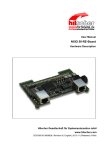
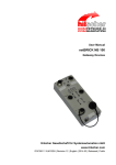
Device Pictures, Connectors and LEDs
9.3.1.9
80/154
Front view of netJACK with VARAN Client
System LED (SYS)
Run LED (RUN)
Error LED (ERR)
LINK LED for channel 0
Interface channel 0
Activity LED (ACT) for channel 0
LINK LED for channel 1
Figure 48: Front view netJACK VARAN Client
Interface channel 1
Activity LED (ACT) for channel 1
Sliding latch
For a description of the LED signals used by VARAN (Client), see section
LEDs VARAN Client on page 97.
For a description of the pinning of the network interface, see section
Pinning Real-Time Ethernet Interface on page 104.
netJACK Communication Module | Installation, Operation and Hardware Description
DOC110504UM04EN | Revision 4 | English | 2013-12 | Released | Public
© Hilscher, 2011 – 2013