1
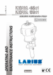
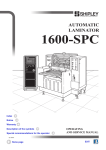
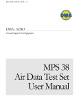
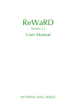
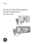
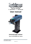
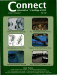
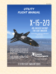
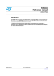
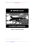
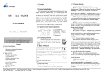
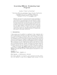
D. MARCHIORI SRL AIR DATA TEST SET MPS-24 DIGITAL PORTABLE USER MANUAL ADDRESS: VIA PONTINA KM. 43.856 – 04011 APRILIA (LT) ITALY TEL: ++39-06-928 2733 – FAX: ++39-06-927 5401 E-mail: [email protected] Internet: http://www.ilink.it/DMA MPS-24 User’s Manual DMM/0722/CP Rev A INDEX 1.0 INTRODUCTION 3 2.0 GENERAL INFORMATION 3 3.0 MAIN PARTS 3 4.0 TECHNICAL DATA 3 4.1 AIR DATA FUNCTIONS FIG. 4-1 MPS-24 AIR DATA TEST SET WITH EXTERNAL MULTIPLE ISOLATOR 4.2 ADDITIONAL FEATURES 4.3 ACCURACY 4.4 POWER SUPPLY REQUIREMENT: 160 W MAXIMUM 4.5 INTERFACES 4.6 DIMENSIONS 4.7 ENVIRONMENTAL 4.8 CALIBRATION 4.9 SELF-TEST TIME AT STARTUP 4.10 OPTIONS 4.11 COMMAND AND CONTROL 4.12 CONTROL CAPABILITY WITH INTERNAL PUMPS 4.13 PROTECTION TO AVOID DAMAGE TO THE INSTRUMENT FIG. 4-2 LAY OUT OF HHRCU 4.14 PROTECTION AGAINST ELECTRICAL POWER LOSS 3 4 4 5 6 6 6 6 7 7 7 7 7 8 9 10 5.0 EQUIPMENT DESCRIPTION 10 5.1 FRONT PANEL FIG. 5-1 MPS-24 FRONT PANEL 10 11 6.0 DESCRIPTION OF THE HHRCU 11 6.1 DISPLAY 6.2 KEYBOARD FIG. 6-1 HHRCU DISPLAY IN OPERATIONAL MODE 11 12 13 7.0 STARTUP 15 8.0 OPERATION 16 8.1 ENTERING ALTITUDE AND AIRSPEED VALUES 8.2 ENTERING PRESSURE VALUES 8.3 CHANGING PRESET LIMITS WITH THE LIMITS MENU FIG. 8-1 HHRCU IN LIMIT MENU 8.4 AMBIENT MEASUREMENT/PAUSE MODE/PANIC BUTTON FIG. 8-2 HHRCU IN MEASURE MODE 8.5 LEAK TEST FIG. 8-3 HHRCU IN LEAK MODE 8.6 VENT FUNCTION 8.7 ENGINE PRESSURE RATIO (EPR) FIG. 8-4 HRCU IN EPR INPUT MODE FIG. 8-5 HHRCU IN EPR CONTROL MODE 8.8 MACH NUMBER 8.9 CENTER LINE CORRECTION 8.10 TRUE AIRSPEED 8.11 VERY LOW AIRSPEED CONTROL 8.12 “CONTROL LOSS” FUNCTION 16 17 17 18 20 21 21 22 22 22 23 23 24 24 24 24 25 Issue Nov. 1998 D. Marchiori PROPRIETARY INFORMATION This material not to be disclosed or reproduced. -1 MPS-24 User’s Manual DMM/0722/CP Rev A 9 PROGRAMMING MPS-24 25 FIG. 9-1 HHRCU IN PROGRAM INPUT MODE FIG. 9-2 HHRCU RUNNING IN PROGRAM MODE 9.1 EXAMPLE: PROGRAMMING THE MPS-24 ACCORDING THE FAR 43, APPENDIX E. 29 29 30 10.0 VALVE CONTROL ADJUSTMENT 33 11.0 HELPFUL SUGGESTION FOR THE GROUND PROXIMITY WARNING SYSTEM TEST 33 12.0 MULTIPLE ISOLATOR CONTROL (OPTION) 34 12.1 EXTERNAL MULTIPLE ISOLATOR 12.2 INTERNAL MULTIPLE ISOLATOR FIG. 12-1 MPS-24 FRONT PANEL WITH INTERNAL MULTIPLE ISOLATOR 34 35 35 13.0 CONTROLLING MPS-24 WITH A PC (OPTION) 36 13.1 SOFTWARE INSTALLATION 13.2 RUNNING THE PROGRAM 13.2.1 GENERAL MENU 13.2.2 OPERATION MENU 13.3 AUTOMATIC TEST 13.4 TEST REPORTING 36 37 37 39 40 40 14.0 CALIBRATION 41 14.1 ZERO CORRECTION 14.2 GAIN CORRECTION 41 42 15.0 USE OF AN EXTERNAL VACUUM PUMP. 43 16.0 ARINC (OPTION) 44 17.0 TROUBLE SHOOTING AND MAINTENANCE SUGGESTIONS. 43 17.1 TEST FOR PNEUMATIC LEAKAGE AND REPAIR. 17.2 CLEANING OF THE PUMP’S VALVES. Issue Nov. 1998 D. Marchiori PROPRIETARY INFORMATION This material not to be disclosed or reproduced. 44 45 -2 MPS-24 User’s Manual DMM/0722/CP Rev A MPS-24 PORTABLE DIGITAL AIR DATA TEST SET USER’S MANUAL 1.0 INTRODUCTION The procedures for using and calibrating the MPS-24 Portable Digital Air Data Test Set (ADTS) manufactured by D. Marchiori s.r.l, Italy are contained in this manual. 2.0 GENERAL INFORMATION The MPS-24 is a portable test set ideal for measuring and controlling the pressures related to altitude and airspeed and their rates of change. These values may be displayed in air data units or engineering units. The MPS-24 is remotely controlled, with a lightweight, sealed, shockproof control unit with a 20-m extension cable. The control unit, to be carried aboard the aircraft, is resistant to shocks received during a free fall of 2 m and is shielded against electromagnetic interference (EMI), according to FCC, Class A, Part 15. 3.0 MAIN PARTS The MPS-24 (shown in Figure 3-1) can be logically divided into six operating subsystems: • Static pneumatic circuitry • Pitot pneumatic circuitry • Internal compressor/vacuum generators • Microprocessor and electronics to read and control the pressures • Vibrating cylinders and very accurate pressure transducers to measure pressures • Hand-held remote control unit (HHRCU) to control functions and display the parameters 4.0 TECHNICAL DATA 4.1 Air Data Functions The MPS-24 generates the following air data test outputs: • Altitude in various units. • Static pressure in various units. Issue Nov. 1998 D. Marchiori PROPRIETARY INFORMATION This material not to be disclosed or reproduced. -3 MPS-24 User’s Manual DMM/0722/CP Rev A • Air speed in various units. • Total pressure in various units. • Simultaneous altitude and airspeed. • Vertical speed (ft/s). • Mach number. • True airspeed calculation. • Engine pressure ratio (EPR or Ptot/Pstat). Figure 4-1 - MPS-24 Air Data Test Set with external multiple isolator 4.2 Additional Features The following functions and features are provided: • Leakage test. Using the LEAK key of the HHRCU, leakage is automatically measured in the desired engineering units per minute. The condition before the leakage test is restored, by pushing the Resume key. This function, also running with the multiple Isolator part number MPS-24EMI (Optional) can separately control up to four Static and four Pitot lines in various combinations. • Vent function. At the end of the instruments test, this function automatically brings the static and pitot lines back quickly but safely to the atmospheric Issue Nov. 1998 D. Marchiori PROPRIETARY INFORMATION This material not to be disclosed or reproduced. -4 MPS-24 User’s Manual DMM/0722/CP Rev A pressure. When the safe condition is reached, the control unit LCD reads Test Set and can be disconnected. • Selectable units: with the SET key of the Control Unit - For altitude: feet and meters. - For pressure: in Hg, hPa, mmHg, and psi. - For speed: kt, m.p.h. and km/h. • Center line correction. To input the altitude difference between the test set and unit under test (UUT). • Programmability of the test. The tests can be made manually by typing the desired altitude, airspeed, and vertical speed values with the keyboard or in two other ways: with pre-defined steps, or with 25 complete preset test profiles. • Vacuum generation. May be used to fasten special adapters with suckers to the aircraft. • Limit values at startup: The ADTS is easily programmable for limit (not to exceed) values of the altitude, speed, vertical speed, Mach number, and speed ratio. The MPS-24 is delivered with the following preset values from the factory: - Minimum altitude: –1,500 ft. - Maximum altitude: 50,000 ft. - Maximum airspeed: 450 kt. - Maximum vertical speed: 6,000 ft/min. - V/t (IAS ratio): 300 kt/min. - Max Mach no.: 1 The user can change these values. The test set can be furnished, upon request, with different default values. - Units of measurement at startup: feet, knots, inHg. • Automatic Protection—Against excessive leakage in Pitot line, running also with large Pitot volumes. 4.3 Accuracy • Altitude: - Range: –2,000 to +85,000 ft with the internal compressor/vacuum pump. - Measuring accuracy: ±3 ft @ sea level with reference to the primary standard - Resolution: 1 ft - Generated signal stability: 3 ft @ 20,000 ft without leakage • Vertical speed: - Range: 0 to 30,000 ft/min, the maximum value can be lowered with keyboard - Accuracy of the vertical speed generation: 50 ft/min or 2% of the set value, whichever is greater Issue Nov. 1998 D. Marchiori PROPRIETARY INFORMATION This material not to be disclosed or reproduced. -5 MPS-24 User’s Manual DMM/0722/CP Rev A • Airspeed: - Range: 10 to 800 kt, with internal pumps - Reading accuracy: 0.4 kt @ 150 kt - Resolution: 0.1 kt over 50 kt, 1 kt from 20 to 50 kt - Stability: 0.2 kt @ 500 kt (0.01 in Hg) - Generated airspeed rate. Default is 150 kt/min, can be set with keyboard up to 500 kt/min • EPR (generation). The engine pressure ratio values are generated referenced to static pressure in inHg. In this function, the default limit Mach Number and Airspeed are not considered: - Range: 0 to 4.0 @ s.l. - Accuracy: 0.002 @ s.l. - Resolution: 0.001 @ s.l. • Mach number: • Range: 0.200 to 4.000 • Accuracy: 0.002 Mach @ s.l. • Resolution: 0.001 Mach • Repeatability: 0.001 Mach 4.4 Power Supply Requirement It is possible to connect the ADTS to power supply sources ranging from 115 to 220 V ac, from 50 to 400 Hz, 160 W 4.5 Interfaces Standard RS-232C. IEEE-488 interface can be supplied as option. ARINC 429 can be supplied as option MIL-1553 can be supplied as option 4.6 Dimensions • Size: 20 in. × 16 in. × 12 in. • Weight: 60 LB 4.7 Environmental • Storage temperature: –20 to +70 °C • Operating temperature: –10 to +50 °C • Sealing. Case and HHRCU splash and rain sealed Issue Nov. 1998 D. Marchiori PROPRIETARY INFORMATION This material not to be disclosed or reproduced. -6 MPS-24 User’s Manual DMM/0722/CP Rev A 4.8 Calibration • Completely performed via internal software through the HHRCU keyboard (firstlevel calibration). • Recoverable error for static and pitot pressure. Without any limitation, it is advisable to send the test set to the manufacturer for an error bigger than 2 mbar. • Self-reconditioning of the control valves is accomplished via internal software, when required to regulate the control parameters of the flow regulators. This operation may be required after long running periods of the test set to re-adapt the software control parameters to the aging of the pressure control valves. 4.9 Self-Test Time at Startup Automatic self-test is initiated at power-on. The MPS-24 is ready for operation in about 60 seconds after power-on. 4.10 Options • Low-voltage power supply section, 22–30 V dc. • Multiple isolator—(External separation box, pneumatically sealed, to directly perform from the control unit, leakage tests on four separate static and four separate pitot lines without repositioning the pipes or hoses; or Internal box, with similar functions). • Readout of the binary code generated by the encoding altimeters. • Software package to connect the ADTS to a PC/AT-compatible computer to perform special test profiles and to record and print the test results (suitable for laboratory operation and to record the test), connecting cable P/N 24-S-PC3 (supplied). Two versions for DOS and Windows95 are available. • IEEE-488 interface. 4.11 Command and Control The lightweight (12-oz) HHRCU has 32 low-profile keys, and a backlit LCD display with three menus as shown in Figure 4-1: • The first menu is the operational one, which shows the target values and the actual ones, plus the units of measurement. • The second menu is used to set the maximum and minimum parameters according to the system under test, to set the speed (indicated air speed (IAS)) variation, and to define the steps AL, AS, and AR to be used during the test. • Another menu is used to insert the values of the preset test profiles. • The beep notifies the operator of the achievement of the target values. 4.12 Control Capability with Internal Pumps The control capability is optimized for the following loads; for special requirements, the MPS-24 can be easily modified for larger volumes: Issue Nov. 1998 D. Marchiori PROPRIETARY INFORMATION This material not to be disclosed or reproduced. -7 MPS-24 User’s Manual DMM/0722/CP Rev A • Static line—With 500 cu in. (8.2 liters), the vertical speed can be controlled at 6,000 ft/min up to 50,000 ft. • Pitot line—The maximum limit speed can be stabilized with a volume of 200 cu in. (3.28 liters). 4.13 Protection to Avoid Damage to the Instrument • Hardware—Intrinsically safe, the electrovalves, normally closed without electrical power, prevent airflow, and do not generate Ps > Pt. Also, the manual regulators do not generate Ps > Pt. • Software—In any case, the above condition is not allowed. • Software limitations— - Max altitude. - Max airspeed. - Max vertical speed. - Airspeed rate. - Max Mach number (Note: Airspeed and Mach number always interact. It is, therefore, impossible to overcome the maximum value of one or the other.) - Software protections—If data entered are larger than software-imposed limitations, the ADTS continues and controls the pressures according to the imposed limitations. Issue Nov. 1998 D. Marchiori PROPRIETARY INFORMATION This material not to be disclosed or reproduced. -8 MPS-24 User’s Manual AIRSPEED ALTITUDE READ RATE 9235 160.9 6025 11000 160.0 6000 717.8 42.6 760.3 1.059 0.286 Ft Kt hP SET PRESS Pt/Ps MACH AL AS DMM/0722/CP Rev A READ SET PRESS UNITS AR SET RESUME MEM VENT MENU CTRL MEAS F1 Fa 1 F4 Fb F3 2 Fd 4 F7 - F2 LEAK F5 3 Fe 5 Fg 7 PROG EXEC DEFAULT AL GO F8 F6 Ff 6 Fh 8 F0 Fc F9 Fi 9 Fz 0 AS AR Norm EPR Figure 4-2 Layout of the HHRCU Issue Nov. 1998 D. Marchiori PROPRIETARY INFORMATION This material not to be disclosed or reproduced. -9 MPS-24 User’s Manual DMM/0722/CP Rev A 4.14 Protection Against Electrical Power Loss In case of electrical power surge, nothing happens to the lines under test. When the electric power comes back, the ADTS senses the pressure in the lines and forces the control system to equalize the measured ones (if altitude are > 8000 feet). Pitot and static lines can be manually discharged using two flow control regulators placed in the front of the test set. The manual discharge operation does not generate pitot negative pressure, or airspeed exceeding 450 kt. 5.0 EQUIPMENT DESCRIPTION 5.1 Front Panel Two regulated pressure ports on the front panel as shown in Figure 5-1 provide connections to the aircraft pressure ports. No. 9 is for the static and no. 10 is for the pitot port. The diameters of the two quick-disconnect couplers are different sizes to preclude incorrect connection. Manual regulators (3 and 4) are used to vent the system in case of electrical power interruption. In case of not recovered electrical power, after the removal of the protection caps, manually open (slowly, counter-clockwise) regulators 3 and 4 together, making sure that the “V” No. 3 does not cause an excessive airspeed, and the “E” No. 4, does not cause an excessive altitude rate. If the ADTS was manually vented before the startup, close the needle valves prior to power-on. Connections to external pressure/vacuum generators must be tightly closed (fittings 5 and 6 of Figure 5-1). Fitting 5 is the positive pressure port, and may be used to apply a positive pressure of not more than 2,000 hPa (relative). This may be used if the internal pressure generator of the MPS-24 is not adequate for the pitot load. Fitting 6 is the vacuum port. It may also be used as a vacuum source or to fasten special adapters with suckers to the aircraft (sometimes used for the static port). This port may be used to connect an external vacuum pump to the MPS-24 to substitute for the internal one. Electrical connectors, switches, and warning lights: - Connection to the electrical power: No. 2. - Connection to the HHRCU: No. 7. Issue Nov. 1998 D. Marchiori PROPRIETARY INFORMATION This material not to be disclosed or reproduced. - 10 MPS-24 User’s Manual DMM/0722/CP Rev A - Connection for the multiple isolator (optional) No. 8. This connector may be used to activate, directly from the HHRCU, the electrovalves of four static and four pitot lines. 5 4 - Manual Vent 6 3 Ext. Press + D. MARCHIORI E Air Data Test Set MPS24 Static V Pitot Remote 14 7 Multiple Isolator Power S/N XXXX 8 9 1. "On/Off" Switch 2. Power Connector 3. Pitot Vent needle Valve 4. Cross bleed needle Valve 5. External Pressure Port 6. External Vacuum Port 7. HHRCU Connector 12 10 11 13 1 2 8. Multiple isolation Connector 9. Static Port 10. Pitot Port 11. Labyrinth pressure equalizer 12. Water extraction button 13. 4A Fuse 14. Power On LED Figure 5-1 MPS-24 Front Panel 6.0 DESCRIPTION OF THE HHRCU The HHRCU is composed of two parts: the keyboard and the LCD. 6.1 Display The scripts written on the frame surrounding the LCD are valid only for the Operation mode. The first line, starting from the upper position, is the line of the measured values. The second line is the line of the target (set) values. The third line is for the pressures (static, pitot, and total). The bottom line shows the Pt/Ps ratio, for the Mach number and for the unit of measure in use. The columns of the first three lines are for the altitude, airspeed, and altitude rate, respectively. Issue Nov. 1998 D. Marchiori PROPRIETARY INFORMATION This material not to be disclosed or reproduced. - 11 MPS-24 User’s Manual DMM/0722/CP Rev A The four-row, 20-column alphanumeric LCD is back-lighted and supports “no light”, plus four levels of back light intensity. Figure 6-1 shows the HHRCU display in the operational mode. 6.2 Keyboard Starting from the upper line, the keys are laid out in the following arrangement (see diagram or the HHRCU): • The LCD UP ARROW key (Ï) (upper left, first row) is used to increase the LCD backlighting intensity level. • The LCD DOWN ARROW key (Ð) (upper right, first row) is used to decrease the LCD backlighting intensity level. • AL, AS, and AR, respectively, are for altitude, airspeed, and altitude rate. These keys are used before the numeric keys to set the desired values. • The SET key is used to change the unit of measurement of pressure. • The VENT key is used to reset the ambient pressure in the static and pitot circuits for the safe disconnection of test lines from the aircraft at the end of the test. • The LEFT ARROW key (Í) is used to delete the last digit entered, if it is incorrect. • The MEM key is used to store data inside the MPS-24 memory. • The LEAK key is used to automatically perform the leak test without a stopwatch. RESUME, written in red at the upper right of the key, is used to restore the previous condition and must be used after the RED SHIFT. • The MENU key is used to switch from the Operative display to the Limits display. • The MEAS key is used to stop the control of the pressure for measuring the parameters without the interference of the pressure control system. This key may be considered the “panic button” to quickly stop the operation of the unit. • The minus key (–) is used to set negative altitudes (static pressure larger than the ambient). • The point key (.) is used to input decimal points for speed and EPR. Issue Nov. 1998 D. Marchiori PROPRIETARY INFORMATION This material not to be disclosed or reproduced. - 12 MPS-24 User’s Manual AIRSPEED ALTITUDE READ RATE 9235 160.9 6025 11000 160.0 6000 717.8 42.6 760.3 1.059 0.286 Ft Kt hP SET PRESS Pt/Ps MACH AL AS DMM/0722/CP Rev A READ SET PRESS UNITS AR SET RESUME MEM VENT MENU CTRL MEAS F1 Fa 1 F4 Fb F3 2 Fd 4 F7 - F2 LEAK F5 3 Fe 5 Fg 7 PROG EXEC DEFAULT AL GO F8 F6 Ff 6 Fh 8 F0 Fc F9 Fi 9 Fz 0 AS AR Norm EPR Figure 6-1 HHRCU Display in Operational Mode • The numeric keys (0–9/F0–9) are used to set the desired values of the controlled parameters when used with RED or BLUE SHIFT functions, F0–F9. (Note: Issue Nov. 1998 D. Marchiori PROPRIETARY INFORMATION This material not to be disclosed or reproduced. - 13 MPS-24 User’s Manual DMM/0722/CP Rev A Some of the “F” legends on the upper position of the numeric keys are not used and can be programmed for custom requirements.) • The UP triangle key (▲) is used to increase, by a pre-programmed step, the different parameters (AL, AS, and AR). • The DOWN triangle key (▼) is used to decrease, by a pre-programmed step, the different parameters (AL, AS, and AR). • The PROG/EXEC/DEFAULT key is used for programming functions. PROGram is used for entering the programming mode, EXECute to initiate the program, and DEFAULT for returning to the operational mode. • The vAL, vAS, vAR (UP/DOWN ARROW) key is used before the previous key to establish the parameter that must be changed. • The BLUE SHIFT key ( ) is used to activate the upper-left functions on the keys, marked in blue. • The RED SHIFT key ( ) is used to activate the upper-right functions on the keys, marked in red. • The GO/ENTER key ( ↵) is used to input the desired data to the MPS-24. • The EPR/NOR key is used to generate a total pressure/static pressure ratio starting from the desired altitude. The blue upper-left NOR on this key is used to reestablish the NORmal air data operation, when used with BLUE SHIFT. 7.0 STARTUP NOTE For correct operation, the MPS-24 must be placed with the front panel face up. The internal vibrating cylinders are slightly sensitive to gravity. Operation with the front panel face up is required for precision readings. Before switching ON the MPS-24 and connecting it to altitude and airspeed ports it must be at ambient pressure. If the altitude in static line is >8000 feet, press VENT. Connect instruments only after TEST BENCH CAN BE DISCONNECTED appears. Remember also to close completely the needle valves before starting the test. For normal operation, perform the following steps: Issue Nov. 1998 D. Marchiori PROPRIETARY INFORMATION This material not to be disclosed or reproduced. - 14 MPS-24 User’s Manual DMM/0722/CP Rev A 1. Connect the static 9 and pitot 10 pneumatic lines to the relevant aircraft or instruments ports. 2. Connect the HHRCU cable to connector 7 on the front panel. If necessary, use the provided 50-ft extension cable. 3. Switch the power switch 1 to ON. 4. After the start-up button is pressed, the MPS-24 Air Data Test Set begins its startup and self-check routine. This routine will take approximately 1 minute. During this period, the following information is displayed: • Serial number of the ADTS • Embedded software issue • Running time in hours • Last calibration date After the self-check routine is complete, the MPS-24 will measure the ambient conditions in the pitot and static ports (or test lines, if connected). If the altitude sensed in the static line is less than 8,000 ft, the MPS-24 will automatically impose the VENT function. When the normal start-up process is complete, the legend “TEST SET CAN BE DISCONNECTED” will appear. When this occurs, press RETURN/GO (↵) to enter the Operational mode. If the ambient altitude measured in the static line is greater than 8,000 ft, the following conditions will be automatically imposed: the set Airspeed will be adjusted to the value measured in the pitot line, the Set Altitude will be adjusted to the value measured in the static line, and the Set AL Rate will be changed to 3,000 ft/min, and VENT function will be not imposed. A repetitive “beep-beep” is used to signal that the target condition has been achieved. Use the BLUE SHIFT/F2 function keys to turn the “beep” feature on or off. If a power loss condition is experienced and manual venting is required due to pressure in the test lines, this can be accomplished by opening the two needle valves (X and Y, Figure 5-1). Be sure the valves are closed after venting is completed. Issue Nov. 1998 D. Marchiori PROPRIETARY INFORMATION This material not to be disclosed or reproduced. - 15 MPS-24 User’s Manual DMM/0722/CP Rev A 8.0 OPERATION 8.1 Entering Altitude and Airspeed Values 8.1.1 Direct Entry To enter an altitude, press the AL key (on the upper row) and enter the desired altitude value using the keypad. After entering the desired value, press the RETURN/GO key. The desired altitude is now entered in the MPS-24, but it will not be reached until an altitude rate greater than 0 is entered. To add an altitude rate value, press the AR key, then enter the numbers of the desired altitude rate with the keypad followed by pressing the RETURN/GO key. To enter an exact airspeed, press the AS key followed by the desired airspeed in knots, then press the RETURN/GO key. When the airspeed value is entered, the MPS-24 will set off toward the target values. 8.1.2 Stepping by Using Arrow Keys This method is a quick method for setting altitude and rate parameters using predetermined altitude steps and the UP ARROW or the DOWN ARROW keys. The step can be programmed with custom step values, or factory preset default values can be used. To step the target altitude, press the UP/DOWN ARROW AL key, followed by the UP ARROW key if the altitude must be increased, or by the DOWN ARROW key if the altitude value must be decreased. To change the altitude rate by stepping, press the UP/DOWN ARROW AR key followed by the UP ARROW or the DOWN ARROW to increase or decrease the desired setting. To change the airspeed by stepping, press the UP/DOWN ARROW AS key followed by the UP ARROW or the DOWN ARROW to increase or decrease the desired setting. For all functions, holding the UP ARROW or the DOWN ARROW key will result in a continuous increase or decrease by the defined step until the key is released. Note that the last UP/DOWN ARROW key function selected is always valid for the UP ARROW or DOWN ARROW function. For example, if a step of 500 has been entered and an altitude of 4,500 ft has been reached using this method, to pass to the altitude of 5,000 ft, the UP ARROW key has only to be pressed once to generate another 500-ft step. Issue Nov. 1998 D. Marchiori PROPRIETARY INFORMATION This material not to be disclosed or reproduced. - 16 MPS-24 User’s Manual DMM/0722/CP Rev A 8.2 Entering pressure Values Pressure values can be entered for static and pitot lines in the required engineering units: The total pressure must always be higher than the static one. To enter a static pressure ( in the displayed unit of measure), press the "Blue Shift” key (left shift) followed by “AL” key, then insert the numeric values of the requested pressure. To enter a differential pressure ( in the displayed unit of measure), press the "Blue Shift” key (left shift) followed by “AS” key, then insert the numeric values of the requested pressure. To enter a total pressure ( in the displayed unit of measure), press the "Red Shift” key (right shift) followed by “AS” key, then insert the numeric values of the requested pressure. 8.3 Changing Preset Limits with the Limits Menu CAUTION Limits are preset at the factory to handle most test standard conditions and to protect most aircraft instrumentation. The operator should use extreme care and caution in setting limits outside of normal operation ranges and when operating the MPS-24 under these limits. Damage to the units under test could occur if caution is not observed. The preset limits will be set as follows: • ALMx is the maximum allowed altitude. • ALMi is the minimum allowed altitude. • ASMx is the maximum allowed airspeed. • MaMx is the maximum allowed Mach number. • ARMx is the maximum allowed altitude/rate. • AS/m is the imposed variation of the airspeed. • DA is the default step interval in feet used for the stepping function. • DS is the default step interval in knots used for the stepping function. • DR is the default step interval in ft/min used for the altitude rate function. To exit from the Limits Menu and to return to the Operation Menu, press the MENU key again. Issue Nov. 1998 D. Marchiori PROPRIETARY INFORMATION This material not to be disclosed or reproduced. - 17 MPS-24 User’s Manual DMM/0722/CP Rev A 8.3.1 Access to the Limits Menu To gain access to the Limits menu, press the MENU key once. The LCD will display the preset limits in the display as shown in Figure 8-1. 8.3.2 Changing Values in the Limits Menu Once in the Limits Menu, to change the limits and the step values, press the SET key. A “>“ symbol will appear in front of the value to indicate the limit to be changed (ALMx). To change its value, insert with the numeric keys the new value followed by the RETURN/GO key. The new altitude limit will be displayed and the ”>“ symbol will shift to the next limit (ALMi). If this parameter has to be changed, proceed as described above. If the value is to be retained, press the RETURN/GO key again to cycle to the next parameter. ALTITUDE READ SET PRESS AIRSPEED RATE ALMx 51000 ALMi -1500 ASMx 450 MaMAx 1.00 ARMx 6000 AS/m 300 DA 500 DS 10 DR 500 Pt/Ps MACH READ SET PRESS UNITS HHRCU in limits mode Figure 8-1 HHRCU in Limit Menu Proceed this way to change or retain the limits and the step values until all the parameters have been cycled through and the “>“ is no longer displayed. At this point, press the MENU key again and the MPS-24 will return to the Operations Menu. The new limits will automatically be utilized by MPS-24 for all future operations at startup. It is possible to have new limits stored as default in the MPS-24 memory. If the new limits are not to be set-up as default, just change the limits using the MENU key, when in the limits menu, press SET and start changing the limits as required. If, the new limits have been selected and it is required to maintain them as default, without switching the MPS-24 Off, when in normal control mode, press Fz, enter the CODE that is 0099. Issue Nov. 1998 D. Marchiori PROPRIETARY INFORMATION This material not to be disclosed or reproduced. - 18 MPS-24 User’s Manual DMM/0722/CP Rev A Be careful, if wrong numbers are stored in this phase, the MPS-24 will not run: in this memory the control parameters and the calibration numbers are stored! After the first parameter comes out, press GO (ENTER) many times (about 35 times) until LSAVE is displayed. The indicated number will be 0 (zero), enter 1 (one) and continue pressing GO (ENTER). When out of the Fine Tuning file, press twice MEM. The new limits are now stored in the non volatile memory of the MPS-24. You can see this by switching Off and On the MPS-24 and check the limits after the new switching On. CAUTION If a unique value has been entered for a particular test, remember to reset the limits after testing to factory or maintenance shop default values to avoid damage to the MPS-24 or aircraft instrumentation. 8.3.3 Changing Units of Measurement While in the Operations Menu, press the SET key. A “>“ symbol will appear before “Ft” (feet). To change to “mt” (meters), press the UP ARROW key followed by the RETURN/GO key and the “>“ will now move before the “kt” (knots) legend. To change to kilometers per hour, press the UP ARROW key; the “>“ will now move before the “Kh” legend. To change to miles per hour, press the UP ARROW key again; the “>“ will now move before the “Mh” legend. When the desired engineering unit for the speed is achieved, press the RETURN/GO key. At this point, the “>“ symbol will move in front of the “In” (inches of mercury or inHg); this is the engineering unit for the altitude, airspeed, and for total pressure (Ptot). To change this parameter, press the UP ARROW key. The possible engineering units options are: “hp” for hectoPascal, “in” for inches of mercury, “mm” for millimeters of mercury, and “pi” for pounds per square inch. After selecting the required engineering units, press RETURN/GO key and the “>“ symbol will disappear. This indicates that all parameters have been selected. 8.4 Ambient Measurement/Pause Mode/Panic Button The MEAS/CTRL function is also used as a pause or “the panic button”. Issue Nov. 1998 D. Marchiori PROPRIETARY INFORMATION This material not to be disclosed or reproduced. - 19 MPS-24 User’s Manual DMM/0722/CP Rev A The MEAS/CTRL key toggles between measurement and control modes. When the MEAS/CTRL key is pressed, the MPS-24 stops controlling pressure and only the pressure measuring system is activated. The circuit under test is now completely isolated from the pressure generator and a precision measurement can be obtained when the line pressures in the system under test and the MPS-24 are stabilized. Whenever a precision measurement is required, especially if large volumes are involved, the MEAS/CTRL function should be used. The MEAS/CTRL can also be used as a “panic button” or pause control to halt operation of the MPS-24 and to give the operator time to investigate a situation. To select the Measurement mode from the Control mode, press the MEAS/CTRL key. When the MEAS/CTRL key is pressed, the HHRCU will show the display shown in Figure 8-2. To resume the previous control condition when the measuring action is over, press the BLUE SHIFT key in the lower left, followed by the MEAS/CTRL KEY (CTRL = Control). This will restore the MPS-24 to Control mode. After using the MEAS/CTRL function it is not necessary to restore the MPS-24 to the previous control state. Press MEAS/CTRL followed by the BLUE SHIFT followed by the MEAS/CTRL key again. The test set will stop the MEAS/CTRL control function and it will be possible to input new target values. ALTITUDE READ SET PRESS 8001 8000 752.7 1.022 Pt/Ps AIRSPEED RATE 100.0 0 MEAS MEAS 16.3 768.9 0.179 Ft Kt HP MACH READ SET PRESS UNITS HHRCU in MEAS mode Figure 8-2 HHRCU in Measure Mode Issue Nov. 1998 D. Marchiori PROPRIETARY INFORMATION This material not to be disclosed or reproduced. - 20 MPS-24 User’s Manual DMM/0722/CP Rev A 8.5 Leak Test This function performs the leak test of the static and pitot lines using a built-in timing function generated by the internal computer quartz clock. Leak rates are calculated every second and are automatically reported in ft/min and kt/min on the Leak menu. Select the leak test function by pressing the LEAK/RESUME key. The HHRCU display in the Leak Test mode is shown in Figure 8-2. For the best measurement, wait until the HHRCU display has become stable. Then press the LEAK/RESUME key again to reset the clock after transition numbers have stabilized for a clean start of the leak test. NOTE It may take up to 30 seconds for the measured value to stabilize. To return to the prior menu, press the RED SHIFT key on the lower right of the keyboard, followed by the LEAK/RESUME key (this resumes the prior condition with action of the red RESUME function of the LEAK/RESUME key). ALTITUDE READ SET PRESS AIRSPEED RATE sec ALTRate ASPRate 10 -15 -0.6 754.0 15.3 769.3 1.021 0.174 Ft Kt hP Pt/Ps MACH READ SET PRESS UNITS HHRCU in LEAK mode Figure 8-3 HHRCU in Leak Mode 8.6 VENT Function The VENT function is used to restore the test circuit to ambient pressure for safe disconnection of the adapters from the aircraft or from the unit under test. Issue Nov. 1998 D. Marchiori PROPRIETARY INFORMATION This material not to be disclosed or reproduced. - 21 MPS-24 User’s Manual DMM/0722/CP Rev A After the VENT key is pressed from an altitude higher than 10,000 ft, the MPS-24 automatically initiates a dive rate of 3,000 ft/min, imposes an altitude of 10,000 ft, and sets the airspeed to zero. When an altitude of 10,000 ft is reached (or if VENT is pressed from an altitude lower than 10,000 ft), the MPS-24 measures the ambient pressure and puts the target value of the static line at the ambient pressure. When the proper conditions to disconnect the hoses are reached, the legend: “TEST SET CAN BE DISCONNECTED” is displayed. To start a new test sequence, press the RETURN/GO key to return to the Operations menu. 8.7 Engine Pressure Ratio (EPR) The engine pressure ratio (i.e., Pt/Ps) measurement is made starting from the desired static pressure value in inHg. Start from a condition where AR is any value that is not equal to zero. Connect test connections per the aircraft maintenance manual and press the EPR key. The HHRCU display (shown in Figures 8-4 and 8-5) will prompt the operator to input the desired values of starting pressure and the desired ratio. Enter the relevant values to input the static pressure in Inches Hg, then the EPR. The MPS-24 will reach and maintain the desired Pt/Ps value. To return to the normal mode, press the BLUE SHIFT followed by EPR. (This returns the test set to the normal mode using the BLUE SHIFT/NORmal function.) ALTITUDE READ ENG. AIRSPEED RATE PRESS. RATIO SET PRESS READ SET Pst: EPR: Pt/Ps PRESS MACH UNITS HHRCU in EPR input mode Figure 8-4 HHRCU in EPR Input Mode Issue Nov. 1998 D. Marchiori PROPRIETARY INFORMATION This material not to be disclosed or reproduced. - 22 MPS-24 User’s Manual ALTITUDE READ SET PRESS AIRSPEED DMM/0722/CP Rev A RATE 26275 321.8 0 26274 EPR 6000 10.500 5.250 15.750 1.500 0.784 Ft Kt in Pt/Ps MACH READ SET PRESS UNITS Figure 8-5 HHRCU in EPR Control Mode 8.8 Mach Number Instead of an airspeed value, the Mach Number can be entered as a control parameter. The procedure is as follows: press BLUE SHIFT then the F0 (also the 0, or zero key). After input of the desired Mach number, press RETURN/GO. The airspeed corresponding to this Mach number at the previously set altitude is now shown in the SET line of the airspeed. If another Mach Number at a different altitude has to be entered, the same procedure must be followed, since the Mach number is only calculated and placed as target AS. Again, this must start from a condition where AR is not equal to 0. 8.9 Center Line Correction If an altitude difference between the ADTS and the UUT is required, the BLUE SHIFT/F3 function key can be used for this purpose. If the altitude value of the UUT is above the ADTS, the correction value must be a positive integer. An “*” before the READ Altitude indicates to the operator that the corrected altitude is being displayed. 8.10 True Airspeed Use the BLUE SHIFT/F4 function key to input the temperature for the true airspeed (TAS). A “T” before the Read Airspeed signals the operator that the TAS is indicated and not the IAS. To restore the IAS reading, press the RED SHIFT/Fd key. Issue Nov. 1998 D. Marchiori PROPRIETARY INFORMATION This material not to be disclosed or reproduced. - 23 MPS-24 User’s Manual 8.11 DMM/0722/CP Rev A Very Low Airspeed control This function is useful when working with helicopters, where very low airspeed (below 30 kts) must be generated and measured. The special function: F5 must be used: this function calibrates accurately the total pressure, equalizing it to the static one. To perform this function, follow this procedure: - vent the MPS-24 at ambient pressure, - when vented, leave the airspeed at zero kts. and put the altitude rate (AR) to zero ft/min, - use a quick disconnect fitting open to ambient to put an maintain the static pressure port at ambient pressure, - operate the F5 function key: this will fully equalize the total pressure as the static one, thus permitting the generation and measurement of very low airspeed, - after some seconds, the total pressure will be exactly equal to the static one, the pressures readings will have a resolution of four decimal points (when in in Hg) and it will be possible to read airspeed from 2 (two) kt. - The readings have no decimal points from 2 to 20 kt (i.e. 4 kt), from 20 kt to the Max allowed AS, the readings have one decimal point (i.e. 22.4 kt). - When very low airspeed must be generated, it is suggested to leave the static port open to ambient with altitude rate (AR) regulated at zero and connect only pitot port at pitot UUT (unit under test) port. - To exit this function, operate the Fg key 8.12 “Control Loss” Function The “Control Loss” function has been added from the software version 5.13. This function shuts off the pressure control when the volume is too high to be emptied or filled up at the desired rate (this fact usually happens when the ADTS is not connected to any closed volume and its hosed are left opened in ambient). Issue Nov. 1998 D. Marchiori PROPRIETARY INFORMATION This material not to be disclosed or reproduced. - 24 MPS-24 User’s Manual DMM/0722/CP Rev A The function avoids the running of the flow valves if the operator does not connect the pneumatic hoses to the instrumentation and, at the same time, commands the ADTS to reach an altitude different from barometric one and/or an airspeed different from “zero”. The function starts to operate if the volume becomes too big for the commanded rate (leaving the pneumatic hose open in ambient is like connecting the ADTS to a very big volume). The intervention of the protection is commanded by “DcSMx” and “DcDMx” parameter in the “fine-tuning” list, accessible with the function “Fz”. “DcSMx” sets-up the intervention point to protect the static line. “DcDMx” sets-up the intervention point to protec the Pitot line, the intervention depends by the set-up values. If the parameter’s value is greater then 300 the function will not work. 9 PROGRAMMING MPS-24. If particular test profiles must be often executed, the MPS 24 can be easily programmed with the desired values of Altitude, Airspeed, Altitude Rate and Airspeed Rate. To do it, press the "Blue Shift" key followed by the DEFAULT key, that means "PROGram" . A new menu appears, prompting the operator to insert or choose the profile No. It is convenient to prepare the requested test profile seating at the desk, with a notebook and the proper aircraft maintenance manual. It is possible to enter 30 test profiles, each one containing 25 control points, each one composed of the following parameters: Altitude, Airspeed, Altitude Rate, Airspeed Rate, wait time (before passing to the following point, L0=stabilization time (for the leak test), L1= measuring time (for the leak test). When the Prog. key is pressed, the following menu appears: The programming phase starts from the symbol "" Issue Nov. 1998 D. Marchiori PROPRIETARY INFORMATION This material not to be disclosed or reproduced. - 25 MPS-24 User’s Manual DMM/0722/CP Rev A To set a new name of the program enter in the program mode pressing the Blue shift followed by the DEFAULT key, a little will blink at the right side of a series of letters. Press the Backspace key 8 times to reach the initial letter. At this point it is possible to write the required letter pressing many times the ▲ or the ▼ key until the wanted letter has been reached, at this point press GO (ENTER): the position of the next letter is now occupied by the little . Repeat the previous steps until the last possible letter has been reached. Remember that it is possible to use every ASCII character passing from the capital letters to the small ones pressing the Blue shift key and to the numbers/symbols pressing again the Blue shift key. Also, if a mistake has been made in this phase, it is possible to correct it pressing the Backspace key and retyping the letter/number/symbol. To store the new name and profile use the F6 function. When the name has been entered, a ">" will flash in front of the Alt value: insert the first step of altitude or confirm the existing one using the GO/ENTER key ( ). ↵ The ">" symbol will now flash in front of Asp. value, insert the Airspeed that must be simulated at that point or confirm it by pressing " GO". Continue inserting the Altitude rate and Airspeed Rate values. At this point the ">" symbol flashes in front of: "Wait". The value to be entered corresponds to the period of time (in seconds) that the MPS-24 will wait before passing automatically to the next step. If 0 (zero) value is entered, the MPS24 will not pass to the next step unless the ▲ (up arrow) is pressed. (note that, also if a value is inserted, it is always possible to pass to the next step by pressing ▲ or to the previous by pressing the ▼ key. After the wait time has been set up, the ">" flashes in front of L0: this corresponds to the stabilization time for the leak check (i.e. the time in seconds to stabilize the pressure before the leak is measured.). If zero value is inserted, the MPS-24 will not perform the stabilization time for the leak check. When the stabilization time has been set up, the ">" flashes in front of L1: this is the measuring time for the leak check (i.e. the time in seconds to measure the leakage). If Zero value is entered, the MPS-24 will not perform the leakage measurement. When the MPS-24 is performing the leak check, the following menu appears: Issue Nov. 1998 D. Marchiori PROPRIETARY INFORMATION This material not to be disclosed or reproduced. - 26 MPS-24 User’s Manual ALTITUDE READ SET PRESS AIRSPEED DMM/0722/CP Rev A RATE 172 100.0 0 A. 500 100.0 0 LEAK WAIT 72 sec Pr: 1 0.160 FAR43&LK Pt/Ps MACH READ SET PRESS UNITS Where LEAK WAIT means that there is still to wait 72 sec to end the leak check ( this depends from the Leak set up time. Usually 60 sec are imposed to stabilize the reading, plus 60 sec to perform the leak check: in total 120 sec.) When the MPS-24 has finished to perform the leak check, the following menu appears, showing the leakage of the static (RA) and of the pitot lines (RS). ALTITUDE READ SET PRESS AIRSPEED RATE 172 100.0 0 A. 500 100.0 0 RA 2 WAIT 999 RS0.4 Pr: 1 0.160 FAR43&LK Pt/Ps MACH READ SET PRESS UNITS In this menu RA 2 means that the leakage of static is 2 ft/min, RS 0:4 shows a pitot leakage of 0.4ft/min and WAIT 999 means that to pass to the next step there is to push the ▲ (up arrow) key. Note that, if at a certain step, a leak check has been programmed, it is suggested to set-up a wait time that leaves the operator enough time to control the leak, or, better, if a wait time = zero is entered, the next step will be reached only if ▲ (up arrow) is pushed. Issue Nov. 1998 D. Marchiori PROPRIETARY INFORMATION This material not to be disclosed or reproduced. - 27 MPS-24 User’s Manual DMM/0722/CP Rev A To execute the programmed profiles, push the "Red Shift" key followed by DEFAULT (that means EXECution): a "*" will precede the first target value shown in the SET AL Line of the display. If the ▲ key is pressed, a capital letter will precede the SET AL advising the operator that the MPS-24 is in Program Mode, in the step defined by the alphabet letter preceding the Set AL. The No. of the program in execution appears for some seconds in place of the units of measure. To choose another test profile, just push the DEFAULT key, operate the PROG key and insert the program No. that is needed, press again the DEFAULT, then EXEC: the defined program will be executed. Each test point corresponds to a letter, the letter corresponding to a particular test point is displayed in the SET line of the display before the Set Altitude: this advises the operator that the MPS-24 is in Program Mode. To pass to the second step, push the ▲ key (or wait the programmed time). Every programmed step can be reached in this way, to go back to the previous step, press the ▼ key, the MPS 24 will immediately control the pressures to reach the requested parameters. To memorize the programmed test profiles, press the "F6" key, the ADTS retains in its memory the profiles also when switched off. To use the MPS 24 in the normal way, press “DEFAULT”. Also when in the PROG. mode, it is possible to insert whichever parameter using the first line AX keys followed by the numeric keys plus the GO/ENTER key ( ). ↵ Issue Nov. 1998 D. Marchiori PROPRIETARY INFORMATION This material not to be disclosed or reproduced. - 28 MPS-24 User’s Manual ALTITUDE READ SET PRESS AIRSPEED DMM/0722/CP Rev A RATE Alt: -1500 Asp: 450 Rate: 6000 Rate: 300 Wait: 15 L0: 0 L: 0 Pr: 0 AAAAAAAA Stp: a Pt/Ps MACH READ SET PRESS UNITS Figure 9-1 HHRCU in PROGram Input Mode ALTITUDE READ SET PRESS 8000 E 8000 22.225 1.031 Pt/Ps AIRSPEED RATE 120.0 0 120.0 6000 0.695 22.920 0.210 Ft Kt in MACH READ SET PRESS UNITS Figure 9-2 HHRCU Running in PROGRAM Mode 9.1 Example: programming the MPS-24 according the FAR 43, appendix E. The parameters of document FAR 43, Appendix E, July 29,1965 for the altimeters test may be stored in the following way. The data of the table 1 must be stored into the MPS-24 memory following the method of previous pages, at the paragraph: PROGRAMMING MPS-24. Issue Nov. 1998 D. Marchiori PROPRIETARY INFORMATION This material not to be disclosed or reproduced. - 29 MPS-24 User’s Manual step Alt A DMM/0722/CP Rev A -1500 Asp 100 Rate 3000 Rate 300 Wait 90 B 0 100 3000 300 C 500 100 3000 D 1000 100 E 1500 F L0 L1 0 0 90 0 0 300 90 0 0 3000 300 90 0 0 100 3000 300 90 0 0 2000 100 3000 300 90 0 0 G 3000 100 3000 300 90 0 0 H 4000 100 3000 300 90 0 0 I 6000 100 3000 300 90 0 0 J 8000 100 3000 300 90 0 0 K 10000 100 3000 300 90 0 0 L 12000 100 3000 300 90 0 0 M 14000 100 3000 300 90 0 0 N 16000 100 3000 300 90 0 0 O 18000 100 3000 300 90 0 0 P 20000 100 3000 300 90 0 0 Q 22000 100 3000 300 90 0 0 R 25000 100 3000 300 90 0 0 S 30000 100 3000 300 90 0 0 T 35000 100 3000 300 90 0 0 U V 40000 45000 100 100 3000 3000 300 300 90 90 0 0 0 0 W 50000 100 3000 300 90 0 0 TABLE 1 To run a correct test profile, the Unit Under Test (UUT), must be tested before for leakage, both for the static and for the Pitot lines. Leakage check can be programmed also from inside the above programmed test profile. If the leak check must be performed within the same test profile, TABLE 1 changes in TABLE 2 at next page (to exclude the static pressure control it is necessary to enter the Altitude rate = zero). In this table, the two steps A & B are related to the leakage of the static and the pitot line. As described at previous pages of this manual, the measured leakage is shown on the HHRCU as RA (for the static) and RS (for the Pitot). Issue Nov. 1998 D. Marchiori PROPRIETARY INFORMATION This material not to be disclosed or reproduced. - 30 MPS-24 User’s Manual DMM/0722/CP Rev A The end of the first point gives the RS value (the value of RA does not have significance): if it is bigger than the allowed value, the test must be stopped and the system must be troubleshot. If there is a good sealing, proceed to the step 2 of the profile. In this case too the value of RS does not have significance. If the leakage is bigger than the allowed value, the test must be stopped and the system must be troubleshot. If the sealing is good, proceed to the step C of the profile (corresponding to point A of TABLE 1) From this point onward, no difference exists between tables 1 and 2. CAUTION: Both the Static and Pitot ports of the MPS24 must be connected to the aircraft. If only the Airspeed Indicator has to be tested, connect to it only the Pitot Port, leaving the Static port of the MPS24 and the one of the Altimeter in ambient. In this case set to ZERO the Altitude Rate to force the MPS24 to not control the Static Pressure. NOTE 1 The waiting time to pass automatically to the next step is set to 90 sec. This is done because the FAR establishes a stabilisation time for the altitude bigger than 60 sec. (and less than 10 min). This allows 30 sec to the operator to read the datum. Issue Nov. 1998 D. Marchiori PROPRIETARY INFORMATION This material not to be disclosed or reproduced. - 31 MPS-24 User’s Manual DMM/0722/CP Rev A NOTE 2 The Airspeed is set up to 100 Kts. for every test point because the test is related to the static system. Also ZERO Kts could be set up for the Airspeed (with the exception of points A and B of TABLE 2). If the Airspeed indicator has to be checked, different Airspeed data can be commanded. The airspeed instrument is tested in a better way leaving the aircraft or the instrument static port in ambient (thus leaving in ambient also the MPS24 static port and setting its AR =0, this removes the control of the static pressure) step A Alt 500 Asp 100 B 5000 C Rate 0 Rate 300 Wait 0 L0 L1 60 30 100 3000 300 0 60 30 -1000 100 3000 300 90 0 0 D 0 100 3000 300 90 0 0 E 500 100 3000 300 90 0 0 F 1000 100 3000 300 90 0 0 G 1500 100 3000 300 90 0 0 H 2000 100 3000 300 90 0 0 I 3000 100 3000 300 90 0 0 J 4000 100 3000 300 90 0 0 K 6000 100 3000 300 90 0 0 L 8000 100 3000 300 90 0 0 M 10000 100 3000 300 90 0 0 N 12000 100 3000 300 90 0 0 O 14000 100 3000 300 90 0 0 P 16000 100 3000 300 90 0 0 Q R 18000 20000 100 100 3000 3000 300 300 90 90 0 0 0 0 S 22000 100 3000 300 90 0 0 T 25000 100 3000 300 90 0 0 U 30000 100 3000 300 90 0 0 V 35000 100 3000 300 90 0 0 W 40000 100 3000 300 90 0 0 X 45000 100 3000 300 90 0 0 Y 50000 100 3000 300 90 0 0 TABLE 2 Issue Nov. 1998 D. Marchiori PROPRIETARY INFORMATION This material not to be disclosed or reproduced. - 32 MPS-24 User’s Manual DMM/0722/CP Rev A 10.0 VALVE CONTROL ADJUSTMENT If after long running periods the MPS-24 does not stabilize well, or works with excessive overrun, use these functions to re-adapt the control capability of the valves. It requires approximately 20 minutes for each circuit to be re-adjusted. This procedure must be run with the MPS-24 disconnected from the UUT because over-pressure generated may damage the instrument. To run it, be sure that no leakage is present in the MPS-24 pneumatic circuitry, since small leakage may cause the program to run longer. For the static line, the Function Key F8 must be used, with the code word of 0099. When the valve’s parameter adjustment is in progress, instead of the units of measure, the script “ADJ STA” appears in the lower-right corner. Ignore the beeps generated in this phase, since they only indicate that the set points imposed by software have been reached. For the pitot line, the Function Key F9 must be used. When the valve’s parameter adjustment is in progress, instead of the units of measure, the script “ADJ PIT” appears in the lower-right corner. After F8 or F9 has been used, wait until the valves restoring program is ended. This is shown by the disappearing of the a.m. scripts and the units of measure are again displayed in the lower-right display. Before memorizing the new control parameters, check stabilization of altitude and speed. If stabilization is good, memorize the new control valves parameters by pressing the MEM key. 11.0 HELPFUL SUGGESTION FOR THE GROUND PROXIMITY WARNING SYSTEM TEST When large volumes are involved (i.e., B-727 and B-747), a special technique must be used. To maintain a constant descent rate of 5,000 ft/min for the “Excessive Sink Rate” test, it is suggested to first achieve an altitude of 11,000 ft with a speed of 360 kt. After 11,000 ft and 360 kt have been reached, the following new target must be entered into the MPS-24: AL = 4,000 ft, AR = 5,500 ft/min, AS = 0 kt. Operate the MPS-24 with the radio altimeter simulator as suggested in the Aircraft Maintenance Manual. Sufficient time is left to make the relevant test at the required descent rate. At the end of the test, change these special set values back to normal parameters. Issue Nov. 1998 D. Marchiori PROPRIETARY INFORMATION This material not to be disclosed or reproduced. - 33 MPS-24 User’s Manual DMM/0722/CP Rev A 12.0 MULTIPLE ISOLATOR CONTROL (OPTION) MPS-24 can be equipped with multiple isolator. There are two options: external and internal. 12.1 External multiple isolator When external multiple isolator P/N MPS-24EMI is furnished for MPS-24, it looks as in Figure 3 –1. It can be controlled with the HHRCU. The connector for the Electric Insulation Box (MPS-24 EMI) is installed only when it is sold together with the MPS-24. But it is possible to install it later, in this case the MPS-24 must be returned to DMA (there is to install additional software and cables) Four static lines and four pitot lines can be controlled using the HHRCU keyboard. Connect the multiple isolator plug connector to the socket of the MPS-24 (Number 7 in Figure 5-1), connect the quick disconnect static socket to the MPS-24 static line, and the multiple isolator pitot plug to the MPS-24 pitot port. Connect the required static and pitot output to the static and pitot lines of the aircraft, and leave the unused lines closed. During normal function, the valves are normally open. To use them, press FI. This function activates the multiple isolator in Leak Mode. FH permits the control of multiple isolator, but in MEAS Mode. Pressing the numbers 1–4 close (and open) the static valves; pressing numbers 5–8 close (and open) the pitot valves. In the lower line of the display, “=” indicates valve open, “x” indicates valve closed. The position, starting from the left of the “=” or the “x,” shows the condition of the relevant valve. Alternatively pressing the same number opens and closes the same valve. Pressing 0 will open all the valves. Pressing 9 will close all the valves. Pressing the RETURN/GO key to resume normal mode (all valves open). 12.2 Internal multiple isolator When internal multiple isolator P/N MPS-24EMI is furnished for MPS-24, the apparatus has different configuration, as defined in the following Figure: Issue Nov. 1998 D. Marchiori PROPRIETARY INFORMATION - 34 This material not to be disclosed or reproduced. MPS-24 User’s Manual DMM/0722/CP Rev A 1. On/Off Switch 9. Static Ports 2. Power Connector 10. Pitot Ports 3. Pitot Vent needle Valve 11. Labyrinth Pressure 4. Cross bleed needle Valve 12. Water extraction button 5. External pressure Port 13. 4A Fuse 6. External Vacuum Port 14. Power On led 7. HHRCU Connector Fig. 12-3 MPS-24 Front Panel with internal multiple isolator It doesn’t need any connector for the Electric Insulation Box. All four static lines and four pitot lines are positioned on front panel. Use the HHRCU keyboard, as in the previous configuration, remembering that during normal function, the valves are normally open. Connect the required static and pitot output to the static and pitot lines of the aircraft, and leave the unused lines closed. The functioning is similar: FI activates the multiple isolator in Leak Mode; FH activates the in MEAS Mode. Issue Nov. 1998 D. Marchiori PROPRIETARY INFORMATION This material not to be disclosed or reproduced. - 35 MPS-24 User’s Manual DMM/0722/CP Rev A Pressing the numbers 1–4 close (and open) the static valves; pressing numbers 5–8 close (and open) the pitot valves. In the lower line of the display, “=” indicates valve open, “x” indicates valve closed. The position, starting from the left of the “=” or the “x,” shows the condition of the relevant valve. Alternatively pressing the same number opens and closes the same valve. Pressing 0 will open all the valves. Pressing 9 will close all the valves. Pressing the RETURN/GO key to resume normal mode (all valves open). 13.0 CONTROLLING MPS-24 WITH A PC (OPTION) The MPS-24PC software package permits controlling the MPS-24 with a personal computer. A PC with this software can be used in lieu of the HHRCU. In addition, it has other functions, such as printing out the results, direct input of pressures, and measuring the pressures in inches Hg with four-digit decimal points. The interconnecting cable P/N 24-S-PC2 and software issue 2.66 (or higher) embedded in MPS-24 are required. The MPS-24 communicates through the serial port of an AT-compatible PC. Hardware required includes an IBM PC AT-compatible computer with FPU co-processor, a videographics adapter (VGA) monitor and serial port (COM 1). 13.1 Software Installation Note that the software package is in DOS format. A new Windows 95 issue will be supplied before summer 1999. Copy the contents of the diskette in a directory of your computer. In this software package, a demo program PROFILI is included with preset test points for the automatic test. The PROFILI program has to be put in the same directory where MPS-24PC software is placed to avoid problems when passing from the manual test procedure to the automatic one. If the supplied test points are not necessary for your needs, they can be easily changed or deleted by running the program PROFILI. A Default file is included, required by the MPS24PC program. If this file is not found, the program will prompt the operator to define a test profile. The program REPORT is also included. It is used to review old test reports and to print them. Issue Nov. 1998 D. Marchiori PROPRIETARY INFORMATION This material not to be disclosed or reproduced. - 36 MPS-24 User’s Manual DMM/0722/CP Rev A 13.2 Running the Program From the directory where the MPS-24PC software has been placed, type “MPS-24PC”, then ENTER. First enter the selection of the RS232 port number. Then, choose the instrument to be tested. Information about the instruments to test and the operator are displayed. To skip this information, just press “ESCAPE”, and the Operation menu will appear. It is possible also to start the control software with the computer not connected to the MPS-24. If so, you will be prompted to check the connection or to wait. If the MPS-24 is not sending any data to the PC (initialization phase or switched off), the program will not show its operation window. As soon as the MPS-24 has terminated its startup, and if it is properly connected, the operation window is displayed. 13.2.1 General Menu Pressing F8 key, the following menu will appear: 1.Operational Test 2.Leak Test 3.Automatic Test Select 4.Reporting of Test 5.Save Test 6.Initial Setting 7.EXIT To execute the desired operation, press the relevant number. • Pressing 1, causes the program to start the test. • Pressing 2 will start the manual leak test (the automatic one can be accessed from inside the automatic test). • To choose the profile for automatic test, press 3. The following menu will appear: 1.Test Profile Review 2.Test Profile List 3.Previous Menu - Pressing No. 2, the profile list will appear. Here it is possible to select the desired one. - Pressing No. 1, the selected profile will appear (no changes are allowed here, the changes are possible only within the "Profile" program). Issue Nov. 1998 D. Marchiori PROPRIETARY INFORMATION - 37 This material not to be disclosed or reproduced. MPS-24 User’s Manual DMM/0722/CP Rev A • Pressing 4, will select the report of the test (if data has been memorized. See next paragraph for memorization: ^F8) • Pressing 5 will save the performed test. • Pressing 6 calls the Initial setting. The following mask will appear: Instrument 1.Altimeter 2.Anemometer 3.Machmeter Choose the type of instrument that has to be tested. After this, the following limit menu appears: Min Altitude (feet) -1500 Max Altitude (feet) 60000 Max Airspeed (knots) 800.0 Max Mach Number 2.500 Max Altitude Rate (ft/min) 6000 Airspeed Rate (Kt/min) 150 Delta Altitude (feet) 100 Delta Airspeed (Knots) 50.0 Delta Altitude Rate(Ft/min) 500 Check for acceptability, validate each value pressing “ENTER” or insert the number that You need. To skip this Menu, press "ESC" After this, the instrument's data are asked. 1^Instrument Code: Description: XXXXXX YYYYYYYYYYY 2^Instrument Code: XXXXXX Description: YYYYYYYYYYY Operator: ZZZZZ ZZZZZ To skip this menu, press "ESC". Issue Nov. 1998 D. Marchiori PROPRIETARY INFORMATION This material not to be disclosed or reproduced. - 38 MPS-24 User’s Manual DMM/0722/CP Rev A 13.2.2 Operation Menu The Operation menu is similar to the HHRCU terminal display. There are three numeric rows of five columns. The upper row is for the measured values, the second row is for the target values, and the third row is for the pressures in inHg. The columns are: first left for altitude in feet or meters and static pressure (Ps) in inHg; second for altitude rate in feet/min or meters/min; third for airspeed in knots, kmph, or mph and dynamic pressure (Pd) in inHg; fourth for airspeed rate in kt/min, kmph/min, or mph/min; and fifth for Mach number and total pressure in inHg. The measuring units in use are shown in the lower left. The bottom of the display is for the commands information. Commands: There are two rows of commands for which F keys are to be used. First Row: • F1= dAL: To increase the altitude in little steps. After the function is selected, ^operate with up and down cursors to increase or decrease the values. • ^F2= dAS: To increase the airspeed in little steps. ^F3= dALR: To increase the altitude rate in little steps. ^F4= ALR: To input the desired value of altitude rate with numbers. ^F6= To vent the system to the ambient pressure. SET: To pass from the direct input of feet (F4) and knots (F5) to the input ^ofF7= Ps (static pressure) and Pd (dynamic pressure). • • • • • ^F8= MEM: To memorize the measured data (for the calibration report). Second Row: • F1= dAL: To increase the altitude of preset step (after the function is selected, operate with the up and down cursor keys to increase or decrease the values). • F2= dAS: To increase the airspeed of preset step. • F3= dALR: To increase the altitude rate of preset step. • F4= AL: To input the desired altitude (or Ps static pressure). • F5= AS: To input the desired airspeed (or Pd dynamic pressure). • F6= MEAS: To stop the control and pass in the Measuring Mode. • F7= PROG: To pass from the manual input of the target points to the ones that have been preset and registered in a file with program PROFILI. • F8= MENU: To pass to the Chooser menu. Issue Nov. 1998 D. Marchiori PROPRIETARY INFORMATION This material not to be disclosed or reproduced. - 39 MPS-24 User’s Manual DMM/0722/CP Rev A • F 10 is not shown and can be used to change the units of measure. For display refresh, if required, press the HOME key. 13.3 Automatic Test If a particular test sequence has to be used often, it is easy to pre-program this sequence, give it a name, and use it in automatic mode. To program a new test sequence or to change an old one, run the PROFILI program. When the required test profile is entered, named, and saved, it may be selected from the MPS-24PC program Chooser menu. From the Operation menu, press the F7 key and pass from one step to another with the F1 (increase) and F2 (decrease). To return to the manual test, press the F7 key again. 13.4 Test Reporting From either test mode, manual or automatic, to memorize a particular value, press ^ F8 and insert the instrument under test reading (the program will prompt the same values of the MPS-24 pressures). The test result can be printed on a printer connected to the parallel port of the PC. To print the memorized data, when in the general MENU, select the REVIEW function. A new menu will appear where each memorized point can be reviewed and a print command can be sent. These points can also be saved on the computer’s hard disk, or on a floppy disk. The program automatically assigns the extension .RPR to each test operation. These files (i.e., TEST1.RPR) can be reviewed and printed when requested, but only by using the program REPORT.EXE. This program may also be installed in another PC used to review and print the test reports. After data is recorded and the Initial Setting of the General Menu is accessed, collected data will be cleared and the test point counter reset to zero. Issue Nov. 1998 D. Marchiori PROPRIETARY INFORMATION This material not to be disclosed or reproduced. - 40 MPS-24 User’s Manual DMM/0722/CP Rev A 14.0 CALIBRATION As delivered, the MPS-24 has been calibrated with a very precise pressure standard and its precision is guaranteed within 4 ft @ s.l. for 1 year. The following calibration procedure achieves the target accuracy if the following conditions exist: • Minimum uncertainty of the primary standard value at the measurement points. • Pressure transducer undamaged. The calibration is made by changing the zero and the gain values. 14.1 Zero Correction The engineering unit for the zero correction must be inHg. The pressure calibrator or the transfer standard must be connected to the Static Port. The altitude of over 50,000 ft must be reached with AS=0. As soon as the altitude has been reached, insert AR=0 and wait until the readings stabilize. When the readings are stable, take note of the three values: calibrator pressure, MPS-24 static pressure (Ps), and MPS-24 pitot pressure (Pt). Assume the calibrator pressure as the true pressure. Operate the Fz key entering the Fine Tuning Mode. Insert the code word (0099), and the MPS-24 variable parameters appear. Ignore the initial parameters used for the fine tuning of the pressure control system. Adjust them up or down and press the GO/RETURN key repeatedly until the “NULLS” (zero static) script appears. Enter the result of the operation as the new NULLS, according to the following formula: New NULLS = True Pressure - Read Ps + Old NULLS Press the GO/RETURN key twice, the script NULLP (zero Pitot) appears. Apply the similar formula to the pitot zero correction: New NULLP = True Pressure - Read Pt + Old NULLP Issue Nov. 1998 D. Marchiori PROPRIETARY INFORMATION This material not to be disclosed or reproduced. - 41 MPS-24 User’s Manual DMM/0722/CP Rev A Press the GO/RETURN key repeatedly until the operative menu appears. At about 50,000 ft the two transducer values must be equal to the calibrator value. If this does not happen, repeat the zero correction, taking particular attention to the “–” or “+” values of the differences. 14.2 Gain Correction Return to the ambient pressure and vent the static line, the pitot line, and the pressure calibrator at the ambient pressure. When the readings are stable, take note of the three values: calibrator pressure, MPS-24 static pressure (Ps), MPS-24 pitot pressure (Pt). Assume the calibrator pressure as the true pressure. Re-enter the Fine Tuning Function by pressing the Fz key. Insert the code word (0099) and, pressing the GO/RETURN key, adjust the various parameters until GAINS (Static Gain) appears. Divide the pressure value of the calibrator by the MPS-24 static pressure and multiply the number obtained by the GAINS value indicated by the MPS-24. Insert the result of this operation as the new static gain: New GAINS = (True Pressure/Read Ps) × Old GAINS Press the GO/RETURN key twice until the script GAINP appears. Divide the pressure value of the calibrator by the MPS-24 pitot pressure and multiply the number obtained by the GAINP value indicated by the MPS-24. Insert the result of this operation as the new pitot gain: New GAINP = (True Pressure/Read Pt) x Old GAINP Press the GO/RETURN key until the operative menu re-appears. Now the pressures indicated by the static and the pitot transducers have to be equal. To save the new calibration data in memory, press the MEM key twice. At the next startup, the MPS-24 shows the new calibration date, after its serial number and the software issue. After the MPS-24 has been calibrated, it is convenient to make a quick check at some points; for example: 0, 25,000, 50,000 ft inputting AS=0 (zero). The difference between the Issue Nov. 1998 D. Marchiori PROPRIETARY INFORMATION This material not to be disclosed or reproduced. - 42 MPS-24 User’s Manual DMM/0722/CP Rev A static and pitot pressures at static conditions (inputting AR=0), should never exceed 0.004 inHg. 15.0 USE OF AN EXTERNAL VACUUM PUMP. If the altitude slew rates or the maximum altitude that can be obtained with the internal pumps are insufficient, an external vacuum pump can be used. Connect the external pump trough the vacuum port (Fig. 2, No. 5). 16.0 429 BUS DATA DISPLAY (ARINC OPTION) Starting from 5.24 software version, it’s possible to have the 429 Bus Data Display (ARINC Option) in the MPS-24. This option consists of a dedicated electronic card inserted into apparatus and two BNC plugs placed on front panel. To activate the ARINC Option, connect the MPS-24 to the aircraft through the BNC connector (High and Low). After connection, push the Fe key ( +5) on the HHRCU. On first time the operation program requires to set the Transmission Rate: RATE: LOW (or HIGH) Use UP key (▲) or DOWN key (▲) to select the correct Rate, then push the GO key. The following Data (Labels) will be displayed: Issue Nov. 1998 D. Marchiori PROPRIETARY INFORMATION This material not to be disclosed or reproduced. - 43 MPS-24 User’s Manual DMM/0722/CP Rev A 203 STANDARD ALT (Ft) 204 BARO CORRECTED ALT (Ft) 205 MACH NUMBER (M) 206 COMPUTED AIRSPEED (Kt) 210 TRUE AIR SPEED (Kt) 212 ALT RATE (Ft/min) 215 DIFFERENTIAL PRESSURE (hPa) 217 STAT PRESSURE (hPa) 234 BARO CORRECTION (hPa) On the HHRCU display Data turn up three at a time under the notice: ARINC SERVICE It is possible to run over Data Index trough UP key (▲) or DOWN key (▲). During Data display, the pressure control mode continues on MPS-24. Pushing alternatively on the GO and Fe keys, it’s possible to pass from operational menu to ARINC Data display (starting from the last selected one). 17.0 TROUBLE SHOOTING AND MAINTENANCE SUGGESTIONS. If the max. altitude or the airspeed cannot be reached, there are two possible causes: pumps wearing (or dirty parts inside their valves) or pneumatic leakage. 17.1 Test for pneumatic leakage and repair. A good way to check for leakage is the following: remove the crate from the box. Remove also the front panel, shut with taps the hoses that eventually remain open. Pay attention to not touch the parts under tension 115 V AC or (220 VAC depending if in USA or in Europe), switch on the MPS-24 and wait for the initialization procedure. If the leakage is on the total pressure line, command an airspeed, eventually leaving the static at ambient with Altitude Rate at zero for not controlling the static valves: Put the MPS24 in MEAS mode. Use pliers with rounded jaws (like the ones used to remove external tab washers) to close one plastic hose at a time. Check, watching at the indication on the HHRCU, when the leakage stops. Issue Nov. 1998 D. Marchiori PROPRIETARY INFORMATION This material not to be disclosed or reproduced. - 44 MPS-24 User’s Manual DMM/0722/CP Rev A When the leakage stops, it means that the leakage is downstream. Go on throttling the plastic hoses until the leakage reappears: this means you have insulated the leaking element. If you damage the plastic hoses, don’t worry, they are standard polyethilene ¼” OD, 0.04” thick. Usually DMA purchases Imperial Eastman Poly-Flo 44P, but whichever other standard polyethilene ¼” OD hose is OK. The elements that have a bigger possibility of leaking are: • fittings of the hoses (blue and red) coming from the regulated static and total pressures to the quick disconnect fittings of the front panel. • Internal closing valve of the quick disconnect fitting of the front panel. 17.2 Cleaning of the pump’s valves. It is easy to disassemble the valves of the pumps since it is possible to do it leaving the pumps installed on the MPS-24. Sometimes it happens that foreign particles obstructs or cause the valves not to perfectly close, thus bringing to a bad efficiency of the pumps. Gain access to the pumps by removing the crate as described at para 16.1. Carefully remove the nuts of the valves with a 2.5 mm. Allen Wrench, taking care to not miss the little internal spring and plastic valve. The red valve body has a spring with a teflon mobile part, the grey valve body does not have a spring and has a polyurethane mobile part. Use a commercial ear cleaner cotton bud wetted in alcohol to clean up the valve hole and the mobile parts. Carefully reassemble the valves in the reverse order they have been disassembled. Reassemble the teflon valve and its spring inside the red body the same way it was installed, taking care to the direction of the internal mobile part; reassemble the polyurethane mobile part inside the grey valve inserting the smooth part facing the pump. If the membrane and the valves parts are damaged, DMA supplies an inexpensive pumps overhaul kit part No. Issue Nov. 1998 D. Marchiori PROPRIETARY INFORMATION This material not to be disclosed or reproduced. - 45 MPS-24 User’s Manual DMM/0722/CP Rev A In any case it is suggested to attend the maintenance and calibration training course that DMA always offers free of charge with every purchase of the MPS-24. Issue Nov. 1998 D. Marchiori PROPRIETARY INFORMATION This material not to be disclosed or reproduced. - 46