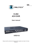
1
DVR
User Manual
3.7 PTZ control...
ChaF l
ProddDs*
i-l M.dotsvir
(adjustable)
* Backup
hard drive, network
playback
1 or 4-way playback at the same time
* Alarm lnput
4 switch input
* Alam output
1 switch output
* PTZ control
RS485
* hard disk interface
2 SATA interface
* Network interface
RJ45 10M/100M self-adaptive Ethemet port
.USB interface a USB2.0 high-speed interface; a USB I.'l interface
* Power
12V 3A-5A
. Loml
fhe eq.ixrcnt b a security sryeillanceprofidltll€EltEficdty
tor lfe seority field, which adopts embedded F!E.I['
d€+{ed
opq'dhg sF:tems, combined with latest tecfinohli= ir I: lf- E, gdr a
vireo ard audio @mpression / de@mprBssirr, ,lg|}.a]€
H ds&
mding,
TCP / lP network technology,and the codes re so-bd -r tE
FIASH, which makes system run more stable. The equipm€fltdlEsrEtE
the fearture of digital video and audio recorder (DVR) and digfrd vibo ald
audio server (DVS), which can not only independently locally, hrt & m a
powerful network of security monitoring through being connected to nefuDrk it
Gn be used in banks, telecommunications, power, justice, transport, residme,
factories, warehouses, water conseruancy facilities and other rields and the
safety precautions of each departments.
chapter 2 intruction of product appearance struct
2-1 Panel Description
2.
i
DVR 4CH
Panel Description
1.2 Technical parameters
* Model
* Operating System
DVR 4CH/8CH/16CH
Embedded Linux Operating System
* system resources
at the same time 4/8/16-channel CIF real-time
video and network transmission, l or 4-channel CIF playback and
4/8/16-channel CIF / QCIF sub-stream
Graphical operation interface,which supports
" Operation interface
mouse, panel, remote control
* Mdeo Standard
PAL, NTSC
* video compression
H.264
*
Audio Compression
ADPCM
* video modes
Manually, timing, alarm, motion detection
* Video query
timesearch, event search, channel search, log search
* Backup modes
network backup, USB backup, SATA DVD
* video input
4/8/16-channel BNC
1-way BNC, 1-way video output
" VGAoutput
*
Audio lnput
4/8/1G-channel BNC
*Audio Output
1 channel BNC
* Monitor quality
PAL: 720x576 (Dl ); NTSC: 720x480 (D1 )
* Playback quality
PAL:352x288 (ClF); NTSC: 352x24O (CIF)
* lmage Control
6-speed adjustable
* Motion Detection
the detection area of each channel ('16 x 16),
which €n be set multi-level sensitivity
Screen
* Video
display
rate
1,4,8,9,16 screen display
PAL: 25 frames / sec (adjustable) NTSC: 30 frames / sec
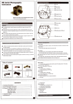
l.Single channel shift button
2.4 video loop previer button
3.Manua1 Recording
button
Direction key
Confirn button
11. The pover indicator
9.
10.
4. filenu
button
12.
5. Auxi I
iary
13. USB
6. PTZ
key
control button
7.
Playback button
B.
Exii button
System running
light
condition indicator
14. Recording condition indicator
15-
Tnfrared receiver
1.The po*er indicator
running liaht
3.Ihe hard disk light
4. Renote control receiver
5. Poser switch button
2, Systen
6.
Direction key
7.
Confirm button
B.
Numeric button
Multiimge preview buftoD
10. PTZ control button
9.
2-
2
DVR 4CH
11.
DVR 8CH
2.22
DVR 16CH
Exit button
12. Menu
13.
Product Interface Description
2.21
button
Recording button
14. playback button
Single frme play button
16. Back button
17. Speeding button
18. Previous video
15.
Product Interface Description
19. The next video
Product lnterface Description
2.3 Remote Control Description
Remote
ontrol mode is the same as
the panel.
DEV button: after pressing DEV key, according to the number keys enter
"OK,, button to save
devie number which is agreement with the host, press
the settings. Then operation of the device takes into force.
recorder which meets requirements, and ensure that middle power outlet of
the hard disk recorder is well grounded. Afler access to power, the device
starts ( POWERI light which is green,and after entering the system, the panel
RUN light normally flashes. Long-press ( POWERI key for 5 seconds to make
the machine soft-off, and the light is red, then again press IPOWERI to
restart.
SHIFT: the current version does not support the key.
3.2 preview
CLEAR: when setting covering and mootion detection region, clear the current
constituency.
Note: when there are more than one device in the same place, remote control
firstly must according to device number select a piece of equipment, so
deflning a unique device number for each device is a must, or remote conlrol
operation may at the same time make effect to more than one device , which
has the same device number.
2.4 Video format
ln the video format switches on the device motherboard, perform video format
settings.
PAL format Status:
After normal equipment boot,immediately enter the preview screen. ln the
preview screen you can see date, time, channel name of the system.Press
number key corresponding to panel or click the left mouse button, you can
preview a single image; then press Panel "Quard" button or click the left
mouse bufton, you can return to a multi-screen preview status.
NTSC format Statu
3.3 Basic operating instructions menu
3.3.1 enter the menu mode
Chapter 3 operating system instructions
I Main Menu / MENU
3.'l on / off
Confirm thai swith-in current and voltage is consistent with the hard
6
)
key to enter the devlce's main menu interface.
IPLAY / PLAYI shortcut keys, enter playback interface
(PTzI
3.3.2
shortcut keys,enter PTZ control interface
menu composition description
Menu component units mainly consist of ihe following categories:
(1) box: provide two kinds of status options,
ineffective,use (conflrm/ENTERI
(Video /
RECI
"i"
means effeclive, "tr" means
keyor (1L
(J) keyorclicktheleft
mouse button to choose.
shortcut keys, enter manually recording interface
For example: in the file search menu page, the "Select Channel" page and the
"video type" check box.
(2) selection box: According to the options contents of the system drop-down
box, selectthetargetcontent. Use (fL IJl keyorclickthe leftmouse button
to select.
For example: in the file search menu page, the "Storage Device" selection box.
(3) list box: query results information display in the list, you
can
select one of
the opeEtion in the provided list to operate accordingly.
For example: in the list of playback query results,pressIconfirm / ENTERI key
or the left mouse button to play the file; you can use the right mouse button to
selecl / €ncel the video file in order to easily backup video files.
(4) edit box: through ihe edit box, enter the target name.
For example: in the System Configuration menu page, the ,'device name,' edit
box, enter numbers, English letters, Chinese and so on.
a) through
the
( FN
I
key or in the
''8",
click the left mouse button to switch
input types, including numbers,case letters, punctuation marks, Chinese input
method.
b) through the panel I
- L ( - I key or the mouse cursor mobilely positioning
location of the edit box, press "ENTER" key or click the Ieft mouse button, then
the enter keyboard appears, through the arrow keys or clicking the left mouse
button to select the target characters which need to be entered .
c) by (SHIFGT
I
key or click the right mouse button to detete the character
before the cursor.
d) After entering,
press IMENUI
key or
(ESCI
Preview mode: in the menu column,you can select the corresponding screen
preview mode,
Shortcut menu: in the menu column, respectively have: video playback,
manual recording, shortcut menu of PTZ control, you can directly emter the
corresponding menu pages.
The main menu bar: after clicking to enter,include: management lools, system
shut down the system of the menu page and so on
key to exit edit status.
(5) button: it's used to perform a specific function or enter tf,e'nexr one sefting
menu, press Imnfirm / ENTERI key and the Ieft mouse button to determine
access.
3.3.3 Exit Menu mode
Press IMENU) , (Exit / ESCI or the right mouse button to exit the menu
mode and switch to a multi-screen preview mode.
Click the right mouse button, return to the previous menu level.
3.4 Main Menu lntroduction
Press MENU key or the right mouse button to pop-up the main menu, main
menu consists of the following three components:
3.5 Video playback
Click "video playback" of the main menu column, enter file search interface
3.5.1 File Search
Select channel: Select the target channel you want to search, click the check
box to choose.
After setting search criteria, click "File Search"
results interface.
then enter
Video Type: Select the video type which needs to search. "i"means to be
checked: "o" means not to be selected.
Time setting: in the edit box enter the beginning and end time to search the
video.
Slorage device: in the selection box select the target backup slorage device.
Search files button: after setting the search criteria, click the button, then the
system begins to search the corresponding video files, and enter the search
results interface.
NOTE: lf video files meeting the search criteria are more than 4000, then the
system only shows the latest 4000 video files. lf you want to find the updated
files, please modify the search criteria.
Playback By time: According to set starting and ending time to start playback of
video material. (No distinction of video types) playback tools control, please
Playback video files: in the search results list box, through the upper and lower
refer to 3.5.3
key or moving lhe mouse to position the target file, click the "ENTER" key or
left mouse button to start playing the file.
By time backup: Backup all video data to the designated storage devices
during the set beginning and ending time.
page curl:Display searched video file by page, you can click "Previous" "Next"
13
button or in the page number box enter the target page
and click the,,Go,,
button to curr page,and you can arso scrofl the mioote oJtton
of mouse to next
interface.
page.
Backup: ln the search results list, through the upper and lower
key moving the
mouse to target file, and then use the FN key or the right
mouse button to
select the file, in the storage equipment selection box,
selJct the target storage
devices, and then click,,Backup', button, then the selected video
file will be
backed up to the target storage device.
Cancel button: return to the previous menu level.
3.5.3 Playback Toot Control
When selecting the file playback or playback by time, it will enter
the video
playback interface.
Pause / Play: Click
playback-
m
button to pause playback, click C! tocontinue to video
Single-frame playback:when it is pause mode, click @ it
playback, and each time click to foMard play oneSlow play: Click @!
to
*itl ue single-frame
slow play, click again to set the slow-play multiples.
Quick play: Clicko to slow play, click again to carry out quick-play multiple
settings.
Previous paragraph / next paragraph: Click 6nor @button, every time click
once of a time or the next section, playback progress will foruard or backward
progress 1 07o.
Close
/ Open Sound: click SIor Elcan open or close the sound of playback
files.
Playback status information: on the right playback tool bar respectively show:
playback speed, play progress, the played time, total time of video file.
Exit Play: Click "ESC" key or button Bto exit playback screen at any time;
afler playing all,automatically quit the playback screen.
3.6 Manual recording
Click the "manual recording" in the main menu column to enter its settings
interface.
[Video / RECI key or in the main menu column, use mouse to click "Manual
recording" to directly enter manually setting recording interface.
Playback toolbar: ln the bottom of playback interface,playback toolbar
wjll
appear, and you can click the right mouse button to hide / show toolbar
When
at the same time Multi-screen is being playback, after hiding tool bar, you
may
by clicking the left mouse button zoon in or out corresponding channel
video.,
Stop Play: Ctick
Q
button, the system will stop ptaying and exit the ptayback
14
3.7 PTZ Control
Click "PTZ control" of in the the main menu column to enter setting interface'
The main operations of PTZ control are: directional control; horizontal sweep;
zoom control; adjust the focal length; adjust aperture; PTZ speed'
After switching page, you can call the preset points; start
/
stop automatic
cruise; wiper control; lighting control; auxiliary equipment control'
Manual Video lnterface Description
Description: The called preset points must be set up, and for the cruising path
setying method see 3.8.2.8 PTZ settings,in which when the set cruise path
number is less than 2 digits, you need to add O to make up enough numbers
before the value of the set corresponding cruise path number'
l\4anual recording interface consists of the following components:
3.8 Menu
Channel number: it corresponds to the video channel of the device.
Channel status: it indicates video status of the corresponding channel, and
status lights are green ,and " ," indicales that no open video; red "*"means to
open the video.
Click "menu" in the main menu column to enter the main menu page, and
one-level menu includs: management tools, system settings, log Query, shut
Video status: when the state lights are surrounded by a coil of " $",and"(t"
means the corresponding channel open lhe network video transmission.
When the system is in recording state (regardless of video type), in the lower
left corner of the channel preview screen will show "6" which means the
system is recording.
Full enable / disable the button: Click the button to stop or open the video
settings of all channels.
Back button: Click the back button, then exit manual recording interface, return
the main menu bar.
10
Nole: Manually start the video, only through the manually stopping, otheMise
the video would continue.
3.8.1 ManagementTools
It includs hard disk management, user management, restore to the default,
clear the alarm, software uPgrades lime settings, version information.
t7
I
Note:
before the hard disk formatting, stop all recording.
I
t
3.8.'1.1 Hard disk management
Create and add users, delele users and modify user information. (the users
except Admin have no rights to set up additional user rights)
Create a new user
Enter the "User Management" interface, click the "Add" button to enter adding
user interface.
SATA: lt displays hard disk information of the curent system, ,,o', means the
success of the hard disk test; "X" indicates means not to detect the hard disk.
Hard Format: ln the hard disk select box, select the target disk, and you can
view the information corresponding to the hard disk, click,,Format', button to
turn up a confirmation page, click "OK,,button to begin formatting the hard disk;
after the hard disk format is completed, the hard disk can be used normally.
button or panel "ENTER" key to select the target user, and then click "Modify"
button, enter the "Modify Usea' page to modify user informationNotes: admin adminislrator can modify permissions of other users.
Delete User
Enter the "User l\4anagement" interface, in the user list, Glick the right mouse
button or panel 'ENTER' key to select the target user, click the "delete" button,
and after confirmation delete the user.
3.8.'l -3 Restore Default
1
, enter the new user name
ln the User Name edit box, enter a new user name (such as the user).
Note: for input methods, see 3.3.2 (4) edit box
2, set the new user's password
ln the "Add User" interface, select "Set Password" button,enter the password
setting page, and directly enter the new password, which is less than six
figures.
3, setting up new user's permissions
ln ihe "Add User" interface, set the new operating authority for the user , within
Restore the system configuration parameters as the factory configuration,and
after restore, the system restarts automatically.
3.1.8.4 ClearAlarm
Manually remove all of the alarm infomation. After the successful removal ol
alarm, the system will give prompt information of "has successfully cleared
warning".
the box of the corresponding function to choose,and "r/" means that the user
can use the permission, "tr" means that the user can not use the permission.
4, save the new user's settings
Click "Conflrm" button to set the new user information to save, and "Cancel"
means not to save.
Modify user
Enter the "User Management" interface, in the user list, click the right mouse
20
After confirmation ,return to managemenl tools the page
21
3.8.1.5 Software upgrade
ln the management tools interface, select ,,software upgrade" to enter its
operation interface.
Enter date and time page, in the "Date", "time" edit box respectively enter the
exact date and time, confirm the save,and cancel to exit.
3.8.'1.7 Version
ln the upgrade option box, select objectives which need to upgrade; in the
upgrade option box, select lhe upgrade mode: FTq or USB_
USB Upgrade: copy the upgrade fites to the root directory of U
disk, and then click OK to upgrade the system.
disk,
plug U
FTP Upgrade: put the upgrade file into the root directory of FTp server,s, and
set the server lP address as the specified address, and finally click OK to
upgrade the system.
After upgrade, the system will automatically restart.
NOTE: Motherboard upgrade file name must be: mainboard.bin; panel
upgrade flle name must be: panel. Bin
When system is being upgraded, don,t disconnect the power supply, so as to
avoid equipment failure.
3.8.1.6 Time Settings
You can see the device name, model, related information ofversion number.
3.8.2 System Settings
ln the main menu page, select "System Settings" to enter its sub-menu
interface.
Equipment name: device name is generally defined as the regional name of
control points, and when remote access, you can intuitively find the monitoring
point what you want to access. The default device name is,,NetDVR',. For
editing method, see 3.3.2 (4) edit box.
Equipment expiration: When selecting "coverage',,and when the hard disk
inside the device are all fully recorded, the system covers the first video data,
to achieve the purpose of circulating the video.
I
I
Keyboard lock timei the system has no operatopm during the set keyboard
lock time, then the system will automatically log off the current user, and il
needs to re-sign-on system to operate.
Switch jng time: switching time is cycle time period of
single-channel preview
display.
Video format: The device supports PAL and NTSC video output formats. The
default output format is "PAL". For setting method please rcfer to 2.4.
3.8.2. 1 System Confl guration
ln the System Settings interface, select "System Configuration,, to enter the
setting interface.
VGA resolutioni the user can adjusi the VGA display resolution according to
VGA monitors
Menu Transparency: After entering the user operation interface,you can by
adjusting the levei of menu transparency to achieve the transparency between
lhe preview screen and menu.
Language: According lo the needs of users, you can set the menu language
type, select Simplified Chinese, English.
Status d;splayr in the preview screen, set whether to display video mode,
status, and open the information icon of motion detection, which is marked as
"i" to show state; it's marked "D" as non-display status.
i
lcon status description in the lower left corner of vhannel preview screen:
"
Device number: When using the remote control to remote and control operate
equipment,which must be through the device number communicating with the
remote control,lhe remote control must correspond to the device number to
achieve remote operation.For the settings of remote control device number,
see the 2.3 instructions.
s
" lndicates that the system is recording video (regardless of video type).
"\:./" lndicates tiTing recording status.
,*.
"-l'
means (he manual recording status.
25
means the system encodes images according to bit rate and video frame rate
' i "...n"
"
* " .."n"
Motion Detection Status
Motion Detection recording
After the page setting is completed, click "OK" button, the settings are saved
and exit; click "Cancel" button, the setting information is not saved and exit.
3.8.2.2 Video Settings
ln the System Settings interface, select "Video Settings,'to enter the settings
interface.
which the user sets; "variable bit-rate" means the system encodes images
according to image quality and video frame rate which the user sets,but the bit
rate is that the system automatically adjust according to the video scene.
Bit rate: the bit rate which users select to encode according to need. The
higher the bit rate, the better the image, but the occupied disk space is largef,
Video frame rate: the video frame rate which users select to encode according
to need. The higher the frame rate,the better the image smooth, but the
occupied disk space is larger.
Copy to: ln the select box on the right of Copy To button, select the target
channel, click the "copy to" button, and the system will apply the current
channel sefting information to other target video channel.
When the page setup is completed, click,,OK" button,then the settings are
saved and exit;,click "Cancel" button, then the setting information is not saved
and exit.
3.8.2.3 lmage Settings
ln the System Settings interface, select "lmage Settings,,to enter the settings
interface.
Select channel: Select the target channel you want to set, click the select box
to select
Stream: Select the code stream which needs to set, which are respectively
"main stream" and "sub-stream."
Stream type: Select the needed video stream type, and "video streaming"
means only to encode the video when the system is recording video;
"composite flow" means to encode audlo and video at the same time when
system is recording
.
Bit rate type: Users can set "fixed rate" and "variable bit-rate", and',fixed rate"
Select channel: Select the channel you want to set, click the select box to
select.
I
channel sefting information to other target video channel. Note: Channel
Channel Name: ln the edit box, the user own can edit the channel names. For
the edit method, see 3.3.2 (4) edit box.
Display Name: "r/" means display, "o" means not to disptay. Click "Location"
button to enter the setting interface,you can via panel keys or the mouse
dragging the red channel name to set, and after set-up, press "ENTER" key or
right mouse button to save and exit, press "ESC" key not to save and exit.
names can not be copied.
After the page setup is completed, click "OK" bufton, the settings are saved
and exit: click "Cancel" button, the information is not saved and exit.
3.8.2.4 Alarm lnput
ln the System Settings interface, select "Alarm lnput" to enter its settings
lmage parameters: Respectively configure the brightness, contrast, hue and
saturation of channel imag,use the panel ( f L ( J ) keys or the mouse to drag
scroll to adjust.
interface.
Use the default values: By clicking the button, you can restore the setting
image parameters to the system default value (only limited to restore the
image parameters).
Cover: in the "cover" option tag set "i", thereby active button of the cover
"regional" to confirm to enter cover region setting interface.
Set cover region: ln the setting interface of cover region,a small yellow box
appears in the regional center, that is the cover setting box. The creation of the
region: through the panel arrow keys moving the yellow box to the beginning
position of the established region, press ( FN I key to (yellow box switches to
the red box each other) turn it into a red box (red box is the cover region box
which takes into force); and then press the arrow keys to adjust the size of the
region, and the minimum can be setto a small square,and the maxium can be
set up to four cover areas. Click the left mouse button or long-press left button
to move the mouse to select area,and after selection,you can press "ENTER"
key or click the middle bufton of mouse to exit and save, "ESC" key not to save
and exit.
Partial elimination: mave the yellow box to the start region which need to be
eliminated(upper left), press(FN I key to enter a small black box (to eliminate
the regional boxes) and the localized area is eliminated. After elimination,
press (confi rm / ENTERI key to save and exit, and if you press (exit / ESCI
key, the elimination operation is invalid. ln the red box, click the left mouse
button or long-press left key to move mouse to eliminate area, click the middle
bulton of mouse to exit and save.
Clear All:
Press
( MENU
I
to clear all covered areas of the channel.
Copy to: ln select box on the right of the Copy To button, select the target
channel, click the "Copy to" button, and the system will apply the current
lnput Channel: Select the channel you want to set, click select box to choose.
Alarm type: you can set high, low voltage, please select the appropriate level
for the alarm corresponding to alarm input channel connection.
Detection: you can set whether to test alarm input signal. Select "Yes" then the
following setting functions take into force; "No" means not to do any treatment.
PTZ linkage: Click the "Settings" button to enter PTZ l,nkage settings interface.
Select a channel number, and perform the relevant settings of PTZ linkage:
preset point, cruise, trajectoryFor PTZ setting methods, see 3.8.2.8
Delay: When alarm input ends, the setting needs the extension of time of
various treatment.
Buzer: Whether to trigger the alarm buzzer
"i"
means enable, "o, means
invalid.
Mdeo Channel: When setting alarm input,you need to trigger the specified
vid@ channel number.
Alarm Output:When sefting alarm input,you need to trigger the specified alarm
output channel number
Time period: "{" enable valid time settings of alarm output, and only during the
effective setting period, alarm signal can be exported.
After the page setup is completed, cljck "OK" button,the setting information is
saved and exit; click "Cancel" bufton, he setting information is not saved and
exit.
3.8.2.6 video deployment
Copy to: ln the select box on the right of Copy To button, select the target
channel, click the "Copy to" button, and the system will apply the current
channel setting information to other target video channel.
ln the System Seftings interface, select',Video deployment" to enter
its
settings interface.
After the page setup is completed, click "OK,,button,the setting information is
saved and exit; click "Cancel" button, he setting information is not saved and
exit.
3.8.2.5 Alarm Output
ln the System Settings interface, select "Alarm output,'to enter its settings
interface.
Select channel: Select the channel you want to set goals, click the select box
to select.
Weeks: Select which day you want to set, and you can sel it separately; ,,All"
means all dates.
Video types and time periods; during the four time periods,you can set different
Output Channel: Select the target channet you want to set, click select box to
choose.
Alarm type: "Normal close-type" and "always open-type,,select corresponding
type.
video types during each period, timing video (red), motion detection recording
(green), alarm recording (yellow). "r/" means enable; ,,tr" means invalid. There
is time period status displaying below and the overall schedule from O to 24
hours.
Copy to: ln the select box on the right of Copy To button, select the target
channel, click the "Copy to" bufton, and the system will apply the current
channel setting information to other target video channel_
After the page setup is completed, click "OK" button,the setting information is
saved and exit; click "Cancel" button, he setting information is not saved and
exit.
3.8.2.7 Video Detection
ln the System Settings interface, select "Video Detection" to enter its settings
i
nterface.
setting cover region.
Sensitivity: Select to trigger motion detection sensitivity. "No detection" means
the above set parameters are invalid.
Copy to: ln the select box on the right of Copy To button, select the larget
channel, click the "Copy to" button, and the system will apply the current
channel setting information to other target video channel.
After the page setup is completed, click "OK" button,the setting information is
saved and exit: click "Cancel" button, he setting information is not saved and
exit.
3.8.2.8 PTZ Settings
ln the System Settings inierface, select "PTZ Settings" to enter the settings
interface.
Select channel: Select the target channel you want to set, click the select box
to select.
Type:you can select motion detection, video loss.
Video Channel: Select the specified alarm oulput channel number which
needs to trigger after detection occurred.
Alarm Output: Select the specified video channel number which needs to
trigger after detection occurred.
Buzzer: Whether to trigger the alarm buzzer. "tr" means enable, "tr" means
Select channel: Select the target channel you want to set, click the select box
to select.
invalid.
Rate: Select the rate which matches the connected PTZ.
Delay: When alarm input ends, the setting needs the extension of time of
various treatment.
Data Bits: Select the data bits which match the connected PTZ.
Regiona: Set motion detection area, and the setting methods , see 3.8.2.3
Stop Bits: Select the stop bit which matches the connected PTZ
Checksum: Select the check value which matches the connected PTZ.
configuration.
Flow Control: The selected item must be consistent with the matched pTZ flow
ontrol seftings.
Protocol Type: The selected item must be consistent with the matched pTZ
Protocol.
Decoder Address: Enter the address of the specified decodef,
Preset point setting: preset point is to preset and memory position, focal length,
aperture and zoom of camera , while using a number to mark these settings.
Add a preset point: ln the pre-edit box enter a preset point,the range of which
is 1-128, and then through the arrow keys to adjust the distance from the
camera to the target location, and after adjustment, press setting, and the
preset point is "saved."
Ethernet @nfiguration:
ln the network conflguration interface, select the "Ethernet Configuration,'to
enter its settings interface.
Delete preset point: ln the edit box enter a preset point which you want to
delete, selecl "Delete."
The cruise path sefting number: cruise path is a path on which the camer runs
at a certain speed, bypassing more than a cruise points which have.serial
numbers,and each cruise point includes preset stop points and stop time, so
the cruise path settings includes the settings of cruise point, preset point, stop
time. cruising speed and other parameters, and in the "settings" interface you
can set he appropriate information. At present, a piece of equipment supports
I 6 cruise path number settings.
Track settings: track is a irregular movement line which camer pre-defines,and
enter "seftings" you mn set the tmjectory.
Copy to:ln the select box on the right of Copy To button, select the target
channel, click the "Copy to" button, and the system will apply the current
channel setting information to other target video channel.
Physical Address: lt displays the physical address number of the device.
After the page setup is completed, click "OK" button,the setting information is
saved and exit; click "Cancel" button, he setting information is not saved and
Port number: The port number must be greater or equal to 2OOO.
exit.
lP Address: The lP address musl be unique and can not conflict with any other
host or workstation on the same network .
3.8.2.9 Network Seftings
Subnet Mask: lt's used to divide the network segment.
ln the System Settings interface, select "Network Settings" to enter the settings
interface, which respectively includes
34
the "Ethernet, PPPOE, DDNS"
Default Gateway: lt's used to achieve communimtion among the different
network segments, Mhich needs to set the gateway address.
saved and exit; click "Cancel" button,the setting information is not saved and
DNS Address: The device uses PPPoE protocol to access network, and it will
get a dynamic IP address.
exit.
DDNS configuration:
ln the network configuration interface, select the "DDNS Configuration" to
enter its settings interface.
Enable Multicast: Select whether to enable multicast.
DHCP: Select whether to enable DHCP to automatically obtain lP.
http port: The port number which lE is browsering to visit, and the default port
number is 80.
is completed, click "OK" button, and the setting
information is saved and exit;click "Cancel" button, the setting information is
not saved and exit.
When the page setup
PPPOE configuration:
ln the network configuration interface, select the "PPPOE Configuration" to
enter its settings interface.
Enable: "r/" means to enable DDNS Dynamic Domain Name Seruice, "tr"
means not to enable the feature.
Select the corresponding seruice providers, and in the edit box enter the user
name, password and domain name. For editing method, see 3.3.2 (4) edit box.
When the page setup is completed, click "OK" button, the setting information is
saved and exit; click "Cancel" button,the setting information is not saved and
exit.
3.9 log information
Enable: "r/" means to enable PPPoE to dial-up,
feature.
"-" means
not to enable the
The user name and password: ln the edit box enter lhe user name and
password which the ISP provides.For editing method, see 3.3.2 (4) edit box.
When the page setup is completed, click "OK" button, the setting information is
ln the main menu page, select "Log query" to enter its interface.
I
Restart: Restart the device,and after confirmation the device will restart.
Close system: Close the device,and after confirmation the device will be
closedCIient lnstructions
When the PC is using the client, you should do the following settings:
1
,
the lE settings: if the first time you use it, and the control does not be loaded,
you need do settings for lE as follows: lnternet Options
-
,,safe-internet_>
Custom Options -> Activex controls and plug-ins are all chosen to enable and
finally Click OK. The following figure:
Main types: in the selection box select query log types.
Time setting: ln the edit box enter the view time period. Click the ,'Search Logs,,
ri
lrl
l,l
tl
bulton,and the corresponding log information will appear at the bottom of the
log list.You can through in the Page box entering the target page, click,,OK,,
button to curl, or scroll the middle mouse button to curl.
rl
rl
3.10
il
shutdown the system
ln the main menu interface, select "shutdown system" to enter its interface.
rii
Login: Open lE and in the address bar, enter the lp address which is set in the
host network settings(the factory lP address is nfip/l1g2.16g.1.Z3), enter the
login page, such as the following picture. Enter the user name and login
password, the user name and password are the same as that of the host side,
and enter the correct user information, then you can successfully login.
In the selection box, select corresponding operation content.
Cancel the user: lt's user to exit the current usel After cancelling, if you want to
continue to use lhe equipment, you need to re-logjn the system.
38
open or close video image of the preview window of
iSri@ilmeans
to open;
-t rk{
the
corresponding to
;
;:.means close status.
,.,",."**
,-
Preview mode: ln the preview mode switching box, you can through mouse
i
----.---,-.
a
*.*" '-' t
|
I
lr
I
r--..-
-.
...
iS&m&or double-click the preview window to switch to a singte
picture or multiple pictures preview mode.
cticting
l
1
| !i ,l :-tl*a!I
.2 bit stream selection
t
.,
-l
The device supports duaFstream, and in the bit stream select box select a
video preview stream type.
r,rL[i. i. r01aiii3]-ar a,ni! -t.ai!.!r.rr.lr'{r.iatrrarrarF..d
i.rEr l'rai.ati,
1.3 PTZ Control
1
i, ,-..{}.
.1 Video Surueillance Main Page
After login, monitoring main page consists of preview window, PTZ control,
preview mode, stream selection, channel open, opening the intercom,
ov^*-
A,
.' -'
,' '
- at'..i. : ,:.:PTZ direction controt button, you can press up and down,
left and right to control the direction of PTZ operation.
B,
&*$ql:
aperture button, you can increase and reduce the control
PTZ aperture.
C, g;pC!&,
focal length button, you can adjust nearer or farther to control
PTZ focus.
D, . glnid S":location button, you can
putl nearer or farther to control the
location of PTZ.
1.4 Advanced Settings box
When preview window closes the video preview, the feature is activated. ln
the corresponding channel preview window, click the right mouse button to
open the Advanced Settings box:
Open
Open preview: ln the preview window, click the left mouse button to select the
target channel (channel which displays as a red box means to be selected),
and in the open box, use mouse to double click the channel number,which can
40
/
Close sound: Through the button open
or close the audio
of
previewing the channel.
Capture: Capture the current video screen and save it as image formats. For
41
saving the directory settings, see 1.5.5 Video Capture save directory
Mdo: Tum on remote recording of the channel video and save it. For saving
the directory settings, see '1.5.5 Video Capture save directory.
PTZ settings: lt's used to set PTZ preset point, the cruise path, tEjectory
settings. For setting method, see 3.8.2.8 PTZ host side settings.
OSD Setting: Set the channel, time, real location of OSD layer, use mouse to
drag location to confirm and saveMotion Detection: Set motion detection area: firstly',r/', means motion detection
area, select "Add area", hold down the left mouse button to drag on the
screen,then grid-like white line appears ,which is detection area; select,'clear
the area ", in the region of the grjdJike white lines , hold down the left mouse
bulton to drag on the screen ,then the region of the gridiike white lines
disappears, and the motion deteclion area is cancelled. ln the sensitivity and
output delay box, select the corresponding parameters.
Screen adjustment: Set the image brightness, contrast, hue, saturation, and
click the left mouse bufton or drag to adjust, when exiting it is automatically
saved.
* - !::,,__,-:_:.hlnr tt1- t1 1 ,
@q. .t*1 rd- r
ffi . flffitue
la-
.
1
.:.
rco-T
@sl"- l'r=
bhloeTtu& l----
qdl
r--1
l6l
ln the setting interface, respectively set the related parameters settings to the
host-side. ln Figure 1-5-'1. The sefting parameters is the same as that of the
host.For the setting methods and considerations, please refer to system
configuration,system information, network operating instructions of the host.
1.5.2 Channel Parameters Configuration
'1.4 lntercom Control
Click to open the Voice to initiately perform voice intercom_
This version doesn't temporarily support voice intercom
1.5 Configuration
1.5. 1 Server Parameter Confi guration
ln the setting interface, respectively set the related parameters settings to the
host-side. ln Figure 1-5-2. The setting parameters is the same as that of the
host.For the setting methods and considerations, please refer to image
settings, video settings, PTZ setup instructions of the host.
42
Set the user information of the device, and the setting parameteB are the
1.5.3
Alam Configuration Parameters
same as that of the host. For the setting methods and considerations, please
refer to user management instructions of the host.
1.5.5 Others
1.5.4 User mnfi guration information
ln the setting interface, respectively set the related parameters settings to the
host-side. ln Figure 1-5-5. The setting parametere is the same as that of the
host.For the setting methods and considerations, please refer to manual
recording, date, time, hard disk management, clear the alarm, log query
software upgrade, restoring the default, tuming off the system sel-up
instructions of the hosl.
Record and capture image to save the directory: preseruing path of setting
path and capturing video.
1.6 Remote Playback
Warranty Gard
Dear Customers:
Thanks for choosing our dvr products. First, please read the instructions below
ofthis card,so
seruies we provide you.
and then fill out the relevant mntent,at the same time please take care
that you can timely and convenient
amss
to quality
Statement:
According to the user instructions and product labeling requirements,any problem
occurred under nomal use and within waranty period, you can hold the warranty
Select video playback channel number,the recording iype and time conditions,
click the Search button, then the left border will show the search result list. you
can scroll the page from top lo bottom or enter the page number to jump to
view the video file (a file display 20 pieces of information, and up to 4OOO).
card for repairs.
File playback: in the search list box, select the target file, double-click the file or
click the "File Playback" button,then the right ptayback window starts to play
the target file,and the playback control is the same as that of the host.
Timing playback: Click "Time Playback" button,then the ptayback window wiil
start playing the video file of the start time which have been set.
lf the following omure,the mmpany d@s not undertake wananty obligations:
Beyond the
lrnprgp€:J
3.
Cotrmitmcntlo the maintenance of non-wananly damage eused by disrontled:
4.
5.
Arbikai\tdsmottionrf the productlabel:
:.-..:
The productname and model number on
ffinty
file.
gry,misrse, uia*horized repat.or modification
_
..
.
cards
En nol mincide with the
product itself
Due to accident, ilresistible
User
User
Download: ln the search list box, select the target file, click,'File Download',
button, and after sefting the preseruing path,it starts to download the target
file. The lower progress bar shows the progress and status of downloading the
waracty peribd:i- .
1.
2.
dafliatd
cog!@y;
Addres
lnfomation
ietffitl
naturdlfactots:
Tel
E-mail
Product Name
Purchase Date
Product model NO.
Wananty Period
Vendor Name
Tel
Address
E-mail:
Product
lnfomation
Vendor
Remarks: The Company reseryes the right to modify the obligations and the needs of
final interpretation.