1
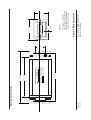
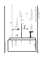
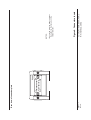
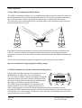
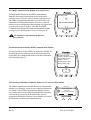
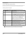
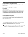
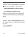
ü
TL-5024
USER`S MANUAL
TL
TL elektronic
Airport, Building 125, Hradec Kralove
503 41, Czech Republic
© Copyright 2004, TL elektronic
Non TSO approved
© Copyright 2004-2006
TL elektronic
All Rights Reserved
Except as expressly provided below, no part of this manual may be downloaded, transmitted, copied,
reproduced, disseminated or stored in any storage medium, for any purpose without the express prior
written consent of the TL elektronic company. Address your questions about the technical information
to TL elektronic. Other information about sale, distribution should be directed to our exclusive
distributors (see World Distributor list on our website).
Producer‘s address:
TL elektronic Inc.
Airport, Building 125,
503 41 Hradec Kralove, Czech Republic
Fax: +420 49 548 23 94 E-mail: [email protected]
Website Address: www.tl-elektronic.com
Please, send your e-mail address to [email protected]
to receive the latest information about the software upgrade.
Send your ideas to [email protected].
We will evaluate your suggestion and provide an update.
Record of revision
Revision
Revision
date
Description
A
1/4/04
Initial Release
B
1/7/04
Language correction
ECO#
Insertion
date
By
--0001
Window is registered trademark of Microsoft Corporation.
All trademarks and registered trademarks are acknowledged.
SchecK® is registered trademark of TL elektronic.
iFamily® is registered trademark of TL elektronic.
sModern® is registered trademark of TL elektronic.
All information in this User‘s manual is subject to change without prior notice.
Page i
Rev. B
TL-5024 USER`S MANUAL
P/N 50-5024-2004
TABLE OF CONTENTS
1. GENERAL DESCRIPTION
1.1. Introduction................................................................................................
1.2. Equipment Description................................................................................
1.3. Technical Specifications..............................................................................
1.4. Limited Conditions......................................................................................
1.5. Limited Warranty.........................................................................................
1.6. Limited Operation........................................................................................
1-1
1-1
1-2
1-3
1-3
1-3
2. INSTALLATION
2.1. Introduction...............................................................................................
2.2. Installation into Panel.................................................................................
2.3. Connection to Aircraft Power.....................................................................
2.4. Antenna Installation....................................................................................
2.5. Alarm Loop Connection .............................................................................
2.6. Instrument Dimensions................................................................................
2-1
2-1
2-1
2-1
2-2
2-3
3. SYSTEM INTERCONNECT
3.1. Pin Function List......................................................................................... 3-1
3.2. TL-5024 Interconnects................................................................................ 3-2
3.3. TL-5024 Connector Location....................................................................... 3-3
4. DESCRIPTION
4.1. How GRPS Communication Module Works.................................................
4.2. GRPS Communication Module as Data-Downloading Device........................
4.3. GRPS Communication Module as Security Device........................................
4.4. Information Provided by GRPS Communication Module................................
4.5. Detecting Availability of Updated Firmware of Connected Instruments...........
4-1
4-1
4-2
4-2
4-2
5. CONFIGURATION
5.1. How to Configure GPRS Communication Module.........................................
5.2. Main Set-up Functions‘ Description..............................................................
5.3. How to Set Parameters in GPRS Communication Module..............................
5.4. How to Edit Detailed Information about User................................................
5.5. How to Set Interval of GPRS Communication Module‘s Connection...............
5.6. How to Set Parameters of Instruments.........................................................
5.7. How to Ask for Downloading Latest Version of Firmware to Instrument.........
5.8. How to Set Detailed Information about Aircraft............................................
5-1
5-1
5-2
5-2
5-2
5-3
5-3
5-3
Page ii
Rev. B
TL-5024 USER`S MANUAL
P/N 50-5024-2004
1. GENERAL DESCRIPTION
1.1. INTRODUCTION
This manual describes the physical, mechanical and electrical features and functions of the TL-5024 GPRS
Communication Module.
1.2. EQUIPMENT DESCRIPTION
The TL-5024 GPRS Communication Module is very sophisticated equipment and complete management
for the wireless transfer of any information or measured values from the instruments of the TL-xx24 series
(or other producers' licensed instruments) in the aircraft at any time and anywhere in the world into your
PC, mobile phone etc.
The GPRS Communication Module includes the new generation of a precise Three-band
GPRS transceiver that provides communication with all GPS / GPRS networks in the world.
The GPRS Communication Module provides security of your aircraft or its parts, such as engine,
storage compartment etc. In this way, it becomes also security equipment, like e.g. in a car.
The GPRS Communication Module can give you information about the voltage of your accumulator,
the temperature and the position of your aircraft, directly to your mobile phone by an SMS message,
or this information may be displayed by an internet browser on your PC.
The GPRS Communication Module provides continuous monitoring of the latest firmware versions
in the instruments of the TL-xx24 series (or other producers' licensed instruments), setting parameters
in the instruments in the aircraft via PC with internet browser etc.
The GPRS Communication Module includes the 16MB memory for storing the measured values from
the instruments, storing the latest firmware of the instruments and other values required by the customer.
1.3. TECHNICAL SPECIFICATIONS
The producer guarantees all stated technical parameters only when the equipment is installed by an
authorized service or an aircraft manufacturer.
1.3.1 Physical characteristics
Width
Height
Depth
TL-5024 Weight
TL-5024 Harness
Page 1-1
Rev. B
57mm (2.244 inches)
38mm (1.496 inches)
170mm (6.692 inches) including connectors with cover
0.20 kg (0.44 lbs)
0.05 kg (0.11 lbs)
TL-5024 USER`S MANUAL
P/N 50-5024-2004
1.3.2 General Specifications
Operating Temperature Range
Humidity
Altitude Range
Power Range
Max. Signalization
Power Consumption
Vibration
-20°C to +70°C
95% non-condensing
4600 meters max.
10.0 to 32.0 Volts
30 Volts, 1 Ampere
0.005 Ampere @ 14 VDC - Stand by mode
0.010 Ampere @ 14 VDC - iFamily® searching
1.58 Ampere @ 14 VDC - Transmition mode
5 to 500 Hz
1.3.3 Long-term Memory
Memory Capacity
Stored Values
Data Saved Endurance
Memory life-time
32MB
All measured values from the TL elektronic
instruments of the series TL-xx24 or higher
10 years
100 000 storings
1.3.4 GSM/GPRS Transceiver
Frequency
GSM Power Class 1
GSM Power Class 4
Data Communication
EMC
Page 1-2
Rev. B
Three-band 900/1800/1900MHz (World wide use)
1W conducted power maximum (30dBm +/- 2 dB),
measured at the antenna port
2W conducted power maximum (33 dBm +/- 2 dB),
measured at the antenna port
TCP / IP protocol, TL elektronic encrypted protocol
FCC Parts 15 & 24, Class B, GSM 11.10, Section 12.2
EN 55022 Class B, FCC Part 22 for GSM 850
TL-5024 USER`S MANUAL
P/N 50-5024-2004
1.4. LIMITED CONDITIONS
1.5. LIMITED WARRANTY
The TL elektronic company warrants this product to be free from defects in materials and manufacture for
three years from the date of purchase. TL elektronic will, at its sole option, repair or replace any
components that fail in normal use. Such repairs or replacement will be made at no charge to the customer
for parts or labour. The customer is, however, responsible for any transportation costs. This warranty does
not cover failures due to abuse, misuse, accident or unauthorized alteration or repairs.
THE WARRANTIES AND REMEDIES CONTAINED HEREIN ARE EXCLUSIVE AND IN LIEU
OF ALL OTHER WARRANTIES EXPRESS OR IMPLIED OR STATUTORY, INCLUDING ANY
LIABILITY ARISING UNDER ANY WARRANTY OF ENCHANT ABILITY OR FITNESS FOR A
PARTICULAR PURPOSE, STATUTORY OR OTHERWISE. THIS WARRANTY GIVES YOU
SPECIFIC LEGAL RIGHTS, WHICH MAY VARY FROM STATE TO STATE.
IN NO EVENT SHALL TL ELEKTRONIC BE LIABLE FOR ANY INCIDENTAL, SPECIAL,
INDIRECT OR CONSEQUENTIAL DAMAGES, WHETHER RESULTING FROM THE USE,
MISUSE, OR INABILITY TO USE THIS PRODUCT OR FROM DEFECTS IN THE PRODUCT.
SOME STATES DO NOT ALLOW THE EXCLUSION OF INCIDENTAL OR CONSEQUENTIAL
DAMAGES, SO THE ABOVE LIMITATIONS MAY NOT APPLY TO YOU.
To obtain warranty service, call the TL elektronic Customer Service (+420 49 548 23 92) for a returned
merchandise tracking number. The unit should be securely packaged with the tracking number clearly
marked on the outside of the package and sent freight prepaid and insured to a TL elektronic warranty
service station. A copy of the original sales receipt is required as the proof of purchase for warranty
repairs. TL elektronic retains the exclusive right to repair or replace the unit or software or offer a full
refund of the purchase price at its sole discretion.
SUCH REMEDY SHALL BE YOUR SOLE AND EXCLUSIVE REMEDY FOR ANY BREACH
OF WARRANTY.
1.6. LIMITED OPERATION
This product is not TSO approved as flight equipment, therefore, the manufacturer
will not be held responsible for any damage caused by its use.
The usage of this product is entirely up to the user's decision.
TL elektronic is not responsible for any possible consequences connected with the operation
of this equipment in the aircraft, particularly if the equipment affected some other
sensitive instruments in the aircraft, or if operation of the equipment infringed laws,
regulations or generally accepted standards in some countries.
Page 1-3
Rev. B
TL-5024 USER`S MANUAL
P/N 50-5024-2004
2. INSTALLATION
2.1 INTRODUCTION
Careful planning and consideration of the suggestions in this section are required to achieve the
desired performance and reliability of the TL-5024.
2.2 INSTALLATION INTO PANEL
It is possible to install the GPRS Communication Module in a random place in the aircraft supposing the
operation specifications are followed.
Before the very installation of the GPRS Communication Module, choose a proper place for installation
of the antenna.
The GPRS antenna should be far enough from the VHF transceiver antenna, so that the undesirable
interference is avoided.
During the installation of the GPRS Communication Module, keep in mind that the antenna cable should
not be longer than necessary, in order to prevent high decrement that reduces the sensitivity of the GPRS
Communication Module.
The antenna cable should be put separate from other cables, in order to prevent possible interference.
If it is necessary to cut the antenna cable short, contact a professional service.
Never fold or curl up the odd antenna cable on a coil. Cutting the antenna cable
should be always given over to a professional service.
A place away from heating vents or other sources of heat generation is optimal.
2.3 CONNECTION TO AIRCRAFT POWER
For the sake of proper working of the GPRS Communication Module, it must be permanently connected
with the battery. Connect the cable of the GPRS Communication Module either directly with the battery, or
with the terminal box, nearest to the battery. In laminated aircrafts, also the GND cable must be put as
close as possible to the battery.
As the GPRS Communication Module is continuously being charged from the battery,
it is necessary to install a wire fuse with the parameters specified on pp. 3-2.
Page 2-1
Rev. B
TL-5024 USER`S MANUAL
P/N 50-5024-2004
2.4 ANTENNA INSTALLATION
If it is possible, install the antenna on the bottom side of the aircraft and keep the distance of at least 80cm
from the ground. If there is a transponder anntena placed on the bottom side of the aircraft, install the
GPRS antenna in the distance of at least 50cm.
2.5 ALARM LOOP CONNECTION
Connect the outlet from the connector P1, pin no. 4 in the way that it creates a grounded loop. For that
purpose, it is necessary to use switching contacts or loops through the connector in the way that in case
of disconnecting the connector or opening the door, the loop is disconnected.
The GPRS Communication Module is delivered with the lock (key) switch that must be necessarily
connected directly to the pin no. 4, and its other terminal must be connected to the skeleton.
This switch bridges the loop and, in this way, prevents the alarm activation and the subsequent sending
information, including calling the phone number set by the user.
According to the diagram, it is also possible to connect a blinking control lamp, which signalizes whether
the alarm is active or not.
Page 2-2
Rev. B
TL-5024 USER`S MANUAL
P/N 50-5024-2004
Page 2-3
Rev. A
Mounting Rack Dimension
Bar.
Type.
Volts.
Amps.
Ser. No.
MADE IN CZECH
-20° to 70°C
Temp. Range.
200 grams
Weight.
Frequency. 900/1800/1900MHz
®
Software version. sModern
GPRS MODULE
133 (5.236)
TL-5024
10.0-32.0
1.5@14 Volts
50ANXXXXX
TL ELEKTRONIC
115 (4.527)
146 (5.748)
TL-5024 USER'S MANUAL
P/N 50-5024-2004
Figure 2. Rack Dimension
1. Dimension: mm (INCH)
2. Unit weight: 0.2 kg (0.44 lbs)
3. Mounting Rack & Hardware
weight: 0.05 kg (0.11 lbs)
NOTES:
6 (0.236)
57 (2.244)
38 (1.496)
25 (0.984)
3.1 PIN FUNCTION LIST
Pin
1
2
3
4
5
6
7
8
9
10
11
12
13
14
15
Page 3-1
Rev. B
Pin Name
Do not connect!
Do not connect!
Do not connect!
Do not connect!
iFamily® communication ISCL
Alarm input
Aircraft ground
Aircraft power
Do not connect!
Do not connect!
Do not connect!
Do not connect!
iFamily® communication ISDA
Aircraft ground
Aircraft power
I/O
----I/O
In
-In
----I/O
-In
TL-5024 USER`S MANUAL
P/N 50-5024-2004
Page 3-2
Rev. A
5
13
IFAMILY® ISCL
IFAMILY® ISDA
TL-5024
GPRS COMM MODULE
6
7
14
AIRCRAFT GROUND
AIRCRAFT GROUND
ALARM INPUT
8
15
P5001
10-32V AIRCRAFT POWER
10-32V AIRCRAFT POWER
Accessories Interconnect
(note. 1)
ISDA
ISCL
Connect other
TL elektronic instruments
via the iFamily® Bus
LEFT
door
Circuit in any connector
to the engine
AIRCRAFT POWER
TL-5024 USER'S MANUAL
P/N 50-5024-2004
Figure 3. Accessories interconnect
1. Alarm is activated when the grounded
alarm input No.6 is disconnected
NOTES:
RIGHT
door
ALARM activate indication
(Red Light Emission Diode - Flashing)
560 ohm
3A
FUSE
Page 3-3
Rev. A
1
9
Rear view of connector plate
15
8
P5001
TL-5024 USER'S MANUAL
P/N 50-5024-2004
Figure 4. Connectors locate
1. Secure the incoming leads to prevent
their effect on the connector in the
vertical direction.
NOTES:
4. DESCRIPTION
4.1 How GRPS Communication Module Works
The GPRS Communication Module is a very sophisticated unit that provides the measured values from
the instruments in the aircraft, information about the position of the aircraft, the condition of the battery,
the aircraft temperature, danger of stealing the aircraft or its parts, and much other information.
The information can be transferred directly to your mobile phone, or this information can be displayed
by an internet browser on your PC.
Inf
orm
ati
o
by n tra
vo ns
ice fe
or r to
SM yo
S m ur m
es obi
sa le
ge ph
s
on
e
GSM tower
s
lue
va ver
d
re ser
su
ea ronic
m
t
f
r o lek
sfe TL e
n
Tra the
to
j
Your aircraft
GPRS tower
If the GPRS Communication Module is connected by the iFamily® Bus with other instruments of the
series TL-xx24 or any other licensed instruments from other producers, always after turning these
instruments on, the measured values will be recorded from the instruments to the GPRS Communication
Module.
The list of licensed instruments/equipment (companies) can be found on the website address:
http://www.tl-elektronic.com/goto.php?goto=ifamily_en.php
4.2 GRPS Communication Module as Data-Downloading Device
If the aircraft is provided with some of our instruments, such as
elektronic
............... INST. ON-LINE ...............
the RPM Meter TL-2824_SAS or the Accelerometer
CONTINUE
GPRS
MODULE
TL-3424_SAS, the GPRS Communication Module will use the
ACCELEROMETER
information from the speed sensor and after finishing the flight,
CONTINUE
BROWSE
the measured values will be recorded from the instruments into
ALTITUDE encoder
the memory of the GPRS Communication Module.
The GPRS Communication Module is (in regular intervals)
connected with the server of the company TL elektronic, in
order to find out whether you asked for downloading the data from the instruments to your PC.
If you did, the GPRS Communication Module would forward this information by the protected protocol
TCP/IP to the server of the company TL elektronic, which, after that, would send the measured values
in a zip file directly to your e-mail box.
Page 4-1
Rev. B
TL-5024 USER`S MANUAL
P/N 50-5024-2004
4.3 GRPS Communication Module as Security Device
An indispensable function of the GPRS Communication
Module is the security function that can secure the whole
aircraft or some of its parts, such as storage compartment etc.
The GPRS Communication Module is provided with a voice
output that will call the phone number you have set and will
inform you in several languages that somebody is trying to steal
your aircraft or some of its parts. After that, the GPRS
Communication Module will send this information in an SMS
message to your mobile phone or in an e-mail to your PC.
Provider
Incoming call:
'
My aircraft OK-CZE
This function is controlled by the pin no. 6
(see point 2.5)
1
2
3
4.4 Information Provided by GRPS Communication Module
It is also possible to use the GPRS Communication Module for
detecting the position of the aircraft, the information about its
temperature, the condition of the battery and other information
described in the point 5.7
Provider
Aircraft: OK-CZE
Position: Airport, Prague
Temperature: 26°C
Battery: 12.6V
Signal quality: 65%
Alarm status: OK
1
2
3
4.5 Detecting Availability of Updated Firmware of Connected Instruments
The GPRS Communication Module also detects automatically
whether a new firmware version of some connected instrument
is available. If the GPRS Communication Module detects a
new version, this firmware will be downloaded into its memory
and, as soon as you turn on the instrument the version is
assigned for, the display will show a query whether you want to
download this version to your instrument or not.
Page 4-2
Rev. B
elektronic
?
NEW FIRMWARE
AVAILABLE.
DO YOU WANT UPDATE?
YES
EXIT
ALTITUDE
encoder
TL-5024 USER`S MANUAL
P/N 50-5024-2004
5. CONFIGURATION
5.1. How to Configure GPRS Communication Module
All settings are done with help of the website or the program TL-control.exe. However, if you want to use
the latter, there must be at least one instrument of the series TL-xx24 on the board of the aircraft.
5.2 Main Set-up Functions‘ Description
The table of the equipment configuration steps is shown below (Initial - firmware version 1.0).
0
1
2
3
4
5
6
7
PASSWORD
Enter your password.
CONNECTION PERIODE Set the interval for connecting the TL-5024 to the server of the
TL elektronic company.
ALARM FUNCTION
Select ENABLE = in case of the disconnected loop, the
TL-5024 will send an SMS message and call the set mobile
phone number to inform on possible stealing of your aircraft.
Or, select DISABLE = the loop will not be checked.
STATUS MESAGE
Select ENABLE = always before connecting the TL-5024 to
the server of the TL elektronic company, the information on
the position, battery condition etc. will be sent to the set
mobile phone number. Or, select DISABLE = status message
will not be sent. The interval for sending the STATUS
MESSAGE is according to the „CONNECTION
PERIODE“ set by you.. The information from the STATUS
MESSAGE are available on the server of the TL elektronic
company anytime the TL-5024 is connected.
YOUR MOBILE NUMBER Enter your mobile phone number.
NO. OF SMS CENTER
Enter the number of the SMS center of your operator
(get this information from the provider).
YOUR EMAIL
Enter the e-mail address to which the TL elektronic company
can send you the data downloaded from your instruments.
VOICE WARNING
Enable or disable the voice warning about operation and
errors of the TL-5024 into your headphones
(Only with use of our Intercom TL-2424 or Voice Module).
All information on this page is subject to change without prior notice. Download the latest
version of the manual from www.tl-elektronic.com and compare with you version of firmware.
Page 5-1
Rev. A
TL-5024 USER`S MANUAL
P/N 50-5024-2004
5.3. How to Set Parameters in GPRS Communication Module
First of all, it is necessary to register the GPRS Communication Module in the GPRS server of the
company TL elektronic.
Fill in the form on the website address:
http://www.tl-elektronic.com/goto.php?goto=gprs_en_login.php
Login: gprs
Password: member
and follow the next instructions.
If you have purchased more GPRS Communication Modules that are to be owned by one user only,
it will be more appropriate if the information about all modules is shown simultaneously. To ensure this,
in the registration form enter the assigned registration number of any GPRS Communication Module
and register the other GPRS Communication Modules in the section "Registration of other GPRS
Communication Modules", which is to be found in the detailed information about the user.
5.4. How to Edit Detailed Information about User
After registering, click on the icon next to the name of the aircraft's user. After that, a window shows
where you have to fill in the e-mail address, to which the GPRS Communication Module will send
the error messages and other information. Here you can also add or delete the GPRS Communication
Modules or edit some other information.
5.5. How to Set Interval of GPRS Communication Module‘s Connection
The interval for sending these messages can be set from 1 minute up to 1 month. It is also possible to
set the interval for the frequency of connecting the GPRS Communication Module with the server
of the company TL elektronic. This interval can be set from 5 minutes up to 5 hours.
Remember that if you set a longer interval, the response to your request for downloading
the data will depend on this interval. This interval does not affect, however, the immediate
response in the case that somebody wants to steal your aircraft or some of its parts.
You should also remember that a short interval may cause faster discharge of your battery.
Page 5-2
Rev. B
TL-5024 USER`S MANUAL
P/N 50-5024-2004
5.6. How to Set Parameters of Instruments
After registering in the „Download“, click on the icon next to the instrument. After that, a window shows,
where you can set some parameters of the instrument, delete maximum values etc.
Remember that the performed changes will be accomplished after registering
the GPRS Communication Module in the server of the company TL elektronic.
As soon as the GPRS Communication Module loads the requests for changing the
parameters in the instrument, the changes or the settings will be accomplished in the
instrument. If the instrument is off, the changes will be accomplished after the turn-on.
5.7. How to Ask for Downloading Latest Version of Firmware to Instrument
The GPRS Communication Module detects automatically whether a new version of firmware is available.
So the user receives the information about the possibility of downloading the updated software directly
on the display of the instrument the firmware is assigned for. The user can either confirm or reject
downloading the firmware by pressing the particular button on the instrument. If the user does not want
the latest firmware of the instruments to be downloaded to the GPRS Communication Module, the box
"Not download firmware to instrument" (in the section of detailed information about the aircraft)
should be ticked.
5.8 How to Set Detailed Information about Aircraft
After registering in the „Download“, click on the icon next to the identification mark of the aircraft. After
that, a window shows where you have to fill in the e-mail address, to which the GPRS Communication
Module will send the information and the data from the instruments. It is also necessary to enter the phone
number, which the GPRS Communication Module will call and send SMS messages to - the information
about temperature, voltage of the battery etc., or in case that somebody wants to steal your aircraft
or some of its parts.
The SMS message you will get is in the following form:
Aircraft: OK-CZE, Position: Airport, Prague,
Temperature: 26°C, Battery: 12.6 Volts,
Signal quality: 65%, Alarm status: OK
Page 5-3
Rev. B
TL-5024 USER`S MANUAL
P/N 50-5024-2004
This page intentionally left blank
Page 6-1
Rev. B
TL-5024 USER`S MANUAL
P/N 50-5024-2004