
1
Express Video Servers
User’s Manual
w w w.stardot.com
Table of Contents
Chapter 1 Configuration..........................................................................5
1.1
1.2
1.3
1.4
1.5
1.6
1.7
Before You Start........................................................................5
What’s Included and What’s Required......................................5
Parts of the Express 2 Video Server.........................................6
Parts of the Express 4 Video Server.........................................7
Parts of the Express 8 Video Server.........................................7
Connecting to a Network...........................................................8
An Overview of Network Connectivity.......................................8
Chapter 2 Installation.............................................................................11
2.1
2.2
2.3
Ethernet Connection............................................................... 11
Wireless Ethernet Connection................................................ 11
Analog or Wireless Modem Connection.................................. 11
Chapter 3 Accessing Express...............................................................12
3.1
3.2
3.3
3.4
3.5
3.6
3.7
3.8
3.9
3.10
3.11
3.12
3.13
3.14
3.15
3.16
Viewing the Video...................................................................12
Accessing the Configuration Menus.......................................12
Image Properties.....................................................................12
Overlay Properties..................................................................15
FTP Properties........................................................................18
Date/Time Properties..............................................................22
Network Properties.................................................................24
Dial-Out Properties.................................................................27
Security Properties..................................................................29
Advanced Menus....................................................................30
Miscellaneous.........................................................................30
Manual Config.........................................................................30
Pan/Tilt/Zoom Functions.........................................................30
Dynamic DNS.........................................................................32
Trigger Properties...................................................................33
Trigger Sensor Connection.....................................................36
Technical Support....................................................................................38
Specifications...........................................................................................40
Express Video Servers
Page 3
Page 4
Express Video Servers
Chapter 1
Configuration
Congratulations on your purchase of a StarDot Express Video Server.
The server provides high quality streaming video from any analog video
source. With proper usage, your video server will provide many years
of quality video. We recommend that you read this manual carefully to
completely understand the video server's capabilities.
1.1 Before You Start
This manual guides you through the basic setup procedure for the
Express video server and provides a detailed resource for the server’s
advanced options and capabilities.
Setting up the video server consists of three steps. The first step is
to configure the network settings. The second step is to configure the
Express server to upload images to a web server (this step is optional).
The third step is the actual physical installation of the video server and
the camera(s) at their final location.
1.2 What’s Included and What’s Required
The package includes the Express Video Server, a power supply,
a network cable (CAT5), a null modem serial cable (for optional
configuration via the Setup Wizard) and the StarDot Tools software.
•
Power source
•
A computer for viewing the Express server video and configuring the
Express server
Note: A computer is not necessary for the video server’s operation. It is only
required to configure the video server and view the live video.
•
Network connectivity (LAN, cable modem, DSL, Dial-Up Internet
Account, etc.)
•
A video source, usually a video camera
Express Video Servers
Page 5
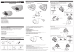
1.3 Parts of the Express 2 Video Server
SW1: Switch In: S-Video, BNC2 Video Loop Output
Switch Out: BNC2 Video Input
SW2: Video Termination, On = Terminate Signal (default)
Looping Output or BNC
Video Input 2
S-Video Input
BNC Video Input 1
SW1
SW2
V1
VIDEO 2
VIDEO 1
(LOOP)
V2
Video Activity LEDs
S-VIDEO
POWER
NET
(RESET)
Power & Network
Activity LEDs
Reset
Front View
TRIGGER I/O
2 x Input
1 x Output Relay
RS-485
Future Expansion
Ethernet Port
TRIGGER I/O
+ - RR
NET
Page 6
DC IN
S1
S0
S0
Serial Port 0, used for Auxiliary
Device Control
Power (DC Power Jack)
12VDC, 1A
RS485
Back View
S1
Serial Port 1, Configuration via PC
serial port
Express Video Servers
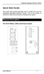
1.4 Parts of the Express 4 Video Server
Power (DC Power Jack)
12VDC, 1A
S0
Serial Port 0, used for
Auxiliary Device Control
4 Video Inputs with
Looping Output
VIDEO INPUTS
RELAY
TRIGGER
RS485
S0
12VDC
VIDEO OUTPUTS
PWR
A
NETWORK
Ethernet Port
B
1
2
3
A
B GND
S1
S1
Serial Port 1,
Configuration via PC serial port
TRIGGER I/O
3 x Input
1 x Output Relay
Back View
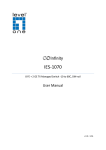
1.5 Parts of the Express 8 Video Server
Power (DC Power Jack)
12VDC, 1A
S0
Serial Port 0, used for
Auxiliary Device Control
8 Video Inputs
VIDEO INPUTS
RELAY
TRIGGER
RS485
S0
12VDC
VIDEO OUTPUTS
PWR
A
NETWORK
Ethernet Port
TRIGGER I/O
3 x Input
1 x Output Relay
B
1
2
3
A
B GND
S1
S1
Serial Port 1,
Configuration via PC serial port
Back View
Express Video Servers
Page 7
1.6 Connecting to a Network
A LAN or network connection is the simplest configuration for the
Express server. The Express server simply needs an IP address (and other
networking parameters) to make the live images and configuration menus
accessible from any web browser on the network. There are two ways the
Express server can be assigned an IP address: automatically or manually.
Install the StarDot Tools software by inserting the included CDROM and running setup.exe.
The StarDot Tools software is the easiest way to configure the
Express server. If your network automatically assigns IP addresses, you
will see the server's IP address listed in StarDot Tools. Simply doubleclick the IP address to browse to the Express server.
If for some reason you don't see the IP address or your network does
not automatically assign IP addresses, you can manually configure the
Express server using the StarDot Tools software:
Connect one end of the null serial cable to the S1 port of the Express
server and the other end into an available serial port on your PC. If
your computer does not have a 9-pin male serial port, you can use a
USB to RS-232 adapter.
Connect the Express server into a network hub, router or switch with
a standard CAT 5 network cable (included).
Run the StarDot Tools software and click on the Setup Wizard
button.
Follow the steps in the Setup Wizard. If you’re unsure of some of the
answers or you’d like more information on connecting the
Express server to the Internet or your private network, read “An
Overview of Network Connectivity”.
1.7 An Overview of Network Connectivity
A LAN or network connection is the simplest configuration for
the Express server. The Express server needs an IP address (and other
networking parameters) to make the live images and configuration menus
accessible from any web browser on the network. There are two ways the
Express server can be assigned an IP address: automatically or manually.
Automatic IP Assignment (DHCP)
The Express server is shipped in an automatic IP assignment
mode called DHCP (Dynamic Host Configuration Protocol). If your
network has a DHCP server (most routers act as DHCP servers), it will
automatically assign the necessary network parameters to the Express
server. Before you can access the server, you will need to know which
Page 8
Express Video Servers
IP address it was assigned. Use the StarDot Tools software to find the IP
addresses of all StarDot servers on your local network.
Automatic IP Assignment (Zeroconf)
If your network does not have a router that automatically assigns
IP addresses (DHCP), the Express server will auto-assign its own IP
address. This is accomplished through Zero Configuration Networking
or Zeroconf. The Express server will give itself an IP address like
169.254.X.Y, where X and Y can be any number between 0 and 255.The
first two numbers will always be 169.254. If your computer or laptop is
not set up with a manual IP address (i.e. it's in DHCP mode), it will also
assign itself its own 169.254.X.Y address. You'll know this is the case if
you see the Express server's IP listed in the StarDot Tools software with a
169.254.X.Y IP address.
If your computer has a manual IP address assigned, you can add a
secondary IP or temporarily change your address to 169.254.100.100 and
set the subnet mask to 255.255.0.0. Once you do this, you should be able
to see the Express server's IP address in StarDot Tools. Double click the
IP address and you can then use a browser to assign it a permanent IP
address (see Chapter 3.3).
Manual IP Assignment
If you want to assign the Express server a permanent IP address, you
will need the following information:
•
•
•
•
IP Address (example: 192.168.1.5)
Subnet Mask (example: 255.255.255.0)
Gateway (example: 192.168.1.1)
DNS Servers (example: 24.1.179.1, 24.1.179.2)
If you are installing the Express server on a company network,
you will probably want to get this information from your system
administrator.
The easiest way to manually configure the Express server is to
connect it to a serial port on your computer. Plug one end of the null
modem serial cable into the S1 port on the back of the Express server
and the other end into an available 9-pin serial port on the back of your
computer (if your PC or laptop does not have a 9-pin serial port, you can
purchase a USB-to-RS232 converter). Press the Setup Wizard button in
the included StarDot Tools software to configure the video server.
Express Video Servers
Page 9
If you don’t have a serial port or using the Windows OS, there are a
few options.
If the video server is connected to a network with a DHCP server
and your computer is not running Windows, you can log into your router
(or whatever is acting as your DHCP server) and view the DHCP clients
table. The Express server will have a MAC address starting with 00:30:F4.
Take note of the IP address and enter it in your web browser. Click on the
configuration link, visit the network tab and assign the camera a manual IP
address (preferrably outside of the router’s DHCP range).
If the video server is connected to a network without a DHCP server
(IP addresses are not automatically assigned) and your computer is not
running Windows, you’ll have to manually assign the camera an IP address.
This requires terminal emulation software and the included null serial cable.
On a Macintosh or on a Windows computer without a serial port, you’ll
need a USB RS-232 adapter.
Before having to go down the path of manually assigning the IP address
via terminal software and a serial port, you may want review the earlier
section on Zeroconf.
To talk directly to the video server via the included null serial cable, set
your terminal software to a bitrate of 38,400 (8/N/1). Log in with username
admin, password admin and use the following commands to assign the
camera a temporary IP address. Once the IP has been assigned, browse to
the video server with a web browser and configure the Express server so it
has a permanent static IP address (see Chapter 3.8).
In the following example, the Express server is being assigned a
temporary IP address of 192.168.0.2 via a terminal program connected to
the S1 port on the back of the video server:
ifconfig eth0 192.168.0.2
route add -net 192.168.0.0 netmask 255.255.255.0 eth0
Once you can reach the video server via its temporary IP address, you’ll
want to immediately assign it a permanent static IP address in the network
configuration menu.
Page 10
Express Video Servers
Chapter 2
Installation
Before installing the Express server in its final location, it is
important to configure and test it first (see Chapter 1).
2.1 Ethernet Connection
If the Express server will be connected directly to an Ethernet
network, measure the distance between it and the nearest Ethernet hub or
switch. This distance should not exceed 330 feet. If you wish to extend
the distance further than 330 feet, you can add an Ethernet hub or switch
between the server and the original switch.
Running Separate Ethernet and Power
Run standard CAT 5 or better Ethernet cable from the hub/switch to
the NET jack on the back of the Express server. Plug the included power
supply into the back of the Express server.
Running Combined Ethernet and Power
To save the hassle of running both power and network cables (or
having to have a 110V or 220V power supply at the the video server
location), StarDot offers combo Ethernet/power cables in lengths of 50,
100, 200 and 300 ft. Contact StarDot for more information
(www.stardot.com)
2.2 Wireless Ethernet Connection
It is possible to turn the Express server into a WiFi device on a
wireless network using external hardware (wireless Ethernet bridge,
wireless Ethernet Access Point configured as a client, etc.). StarDot does
not provide wireless Ethernet equipment.
2.3 Analog or Wireless Modem Connection
Because of the limited bandwidth of analog modem connections,
StarDot does not recommend using the Express server with an analog
modem.
Some wireless modems provide higher speeds than traditional analog
modem connections. It is possible to use the Express with a cellular
connection. Contact StarDot Technologies for more information.
Express Video Servers
Page 11
Chapter 3
Accessing Express
3.1 Viewing the Video
Any Javascript or Java-enabled browser can be used to view the
live video. Type the Express IP address in your browser’s address bar
(example: http://192.168.1.5) or use StarDot Tools to find the
camera’s IP address.
3.2 Accessing the Configuration Menus
Virtually any web browser can be used to access the Express server's
configuration menus. To access these menus, type the IP address in your
browser’s address bar (example: http://192.168.1.5). This will
bring up the live image page. Click on the Configuration link to access
the configuration menus. You will be prompted for a User Name and
Password. Use admin for both.
Tip:
We highly recommend that you change the default password. To do so, see
Chapter 3.10.
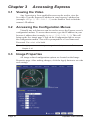
3.3 Image Properties
All image-related configuration options are located on the Image
Properties page. After making changes, click the Apply button to save the
new settings.
Page 12
Express Video Servers
PROCESSING
Resolution
Resolution is the dimensional size of the image, measured in pixels.
The higher the resolution, the larger the picture appears in your browser,
and the longer it takes to download.
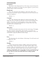
Brightness
This value determines the brightness of the image. Most video
cameras have automatic exposure compensation so you'll rarely need to
adjust the brightness.
Default: 100
Contrast
This value determines the amount of contrast in the image. The
higher the value, the larger the difference between dark and light areas
will be. Conversely, low contrast produces a hazy image with little
difference between the dark and light areas. In most cases, this value
should be left at its default value.
Default: 64
Saturation
Saturation determines the amount of color in the image. The higher
the value, the more saturated the colors become. Conversely, low
saturation produces an image with little color information. A value of 0
will produce a grayscale (black & white) image.
Default: 64
Hue
Hue determines the color balance of the image. You will rarely need
to change this value.
Default: 0
Quality
Quality represents the amount of JPEG compression performed
on the image. A high value produces the highest quality image at the
expense of file size (and transfer speed). A low value produces a small
file size (and hence, quicker transfer speed) at the expense of image
quality. A compromised value in the range of 50-80 is recommended. A
value higher than 80 is not recommended, as it greatly increases the
file size with very little noticeable difference in image quality.
Default: 80
Express Video Servers
Page 13
Size
You can limit the JPEG frame size as a means of throttling
bandwidth. The value is in kilobytes (KB). 0 means no maximum.
Frame Skip
To lower the frame rate (and bandwidth), increase this value. A value
of 0 means full frame rate, a value of 1 means skip every other frame, a
value of 2 means skip every two frames
Default: 0
LED
The video input activity LEDs can be configured in a number of
different ways:
Page 14
•
Off - LED is always off.
•
Always Green - LED is always on and green.
•
Green-Yellow Active - LED remains green until image activity
occurs (viewing, recording, FTP, etc.), in which case it momentarily
blinks yellow.
Express Video Servers
3.4 Overlay Properties
The Overlay Properties allow you to edit the text displayed on the
video frames.
TIME/DATE/TEXT STAMP
Text
Any text entered into this field will be stamped onto the live image.
Camera location and copyright information are two examples. In addition to
static text, the current date and time, as well as internal camera parameters,
can all become part of the text on the live image. This is handled through
markup characters. For instance, %d inserts the current day of the month
on the live image. There is a complete list of markup characters below and
a mini reference on the Overlay page itself.
Default: Express XL %a %b %d %H:%M:%S %Y
Camera $I Frame $n
Scale
The size of the font can be scaled from 1x (smallest size) to 4x (largest
size). The larger fonts sizes are useful for high resolution images that are
being resized smaller on a web page.
Express Video Servers
Page 15
Markup Character Reference
All of the following markup characters can be used in the text overlay.
Additionally, any date/time markups (preceded by the % character) can be
used to compose the filenames in the FTP Properties Page, which is very
useful for archiving images with unique filenames (based on the current
date and time, for instance).
Date Markups
%Y
Year, Four-Digit [2000-2199]
%y
Year, Two-Digit [00-99]
%m
Month, Numerical [01-12]
%B
Month, Full [January-December]
%b
Month, Abbreviated [Jan-Dec]
%U
Week of Year (Starting with Sunday) [00-53]
%W
Week of Year (Starting with Monday) [00-53]
%d
Day of Month [01-31]
%w
Day of Week, Numerical (Sunday=0) [0-6]
%u
Day of Week, Numerical (Monday=1) [1-7]
%A
Day of Week, Full [Sunday-Saturday]
%a
Day of Week, Abbreviated [Sun-Sat]
%j
Day of Year (Julian Day) [001-366]
%p
AM/PM, Uppercase
${Z}
Time zone
Time Markups
%H
Hour, Military [00-23]
%I
Hour, Standard [00-12]
%M
Minute [00-59]
%S
Second [00-59]
$[
Milliseconds [000-999]
Date & Time Shortcut Markups
Page 16
%D
Date String [mm/dd/yy]
%r
Time String [HH:MM:SS AM/PM]
%T
Time String, Military [HH:MM:SS]
Express Video Servers
Symbol Markups
\260
Degree Sign, º
\251
Copyright Sign, ©
\256
Registered Sign, ®
\261
Plus-Minus Sign, ±
%%
Percentage Character, %
Camera Markups
${IF}
Internal Server Temperature, in Fahrenheit
${IC}
Internal Server Temperature, in Celsius
${F}
Weather Station Temperature, in Fahrenheit
${C}
Weather Station Temperature, in Celsius
${HUM} Weather Station Relative Humidity
${MB} Weather Station Pressure in Millibars (hPa)
${HGIN} Weather Station Pressure in Inches of Mercury
${HGMM} Weather Station Pressure in Millimeters of Mercury
$n
Frame Number
$u
Camera Uptime
The Express server supports much of the ISO 8859-1 character set,
which is very useful for adding foreign language text to the overlay. In most
cases, you can also copy and paste characters from other applications.
Express Video Servers
Page 17
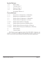
3.5 FTP Properties
The FTP Properties instruct the Express to upload images to a
remote server. After making changes, click the Apply button to save the
settings in the video server.
FTP Upload
FTP stands for File Transfer Protocol, one of the most popular methods
for transferring files over the Internet. In addition to camera serving images
from its internal web server, it can also upload images to an external web
server. This is useful if you plan on having a large number of visitors viewing
the live images or if you’d like to archive every image the camera takes.
To enable image uploads, check FTP Upload on and fill out the options
below.
Required Fields
Hostname
The hostname is the name of the server where you’d like the camera to
upload images to. It can be a machine name or IP address. Do not include
the http:// or ftp:// header or a path.
Example: example.com or ftp.example.com
Page 18
Express Video Servers
Username
This is the username or login name assigned to you by your hosting
company.
Password
This is the password assigned to you by your hosting company.
Path/File
This field combines two elements, the image filename, preceded by an
optional path or directory. Ask your web host if you need to use a directory
path for the image filename. Otherwise, you can just use the filename of
the JPEG image.
Example Without Path: camera.jpg
Example With Path: /html/images/camera.jpg
Advanced Fields
Rotating Archive
If enabled, the Express will use a renaming scheme to store the last
10 images on your server. A hyphen, followed by the archive number
(0-9) is automatically appended to the end of the filenames.
Default: Off
Passive Mode
If the Express is behind a proxy server, enable passive mode. If you are
unsure if you need passive mode, it is usually safe to enable it anyway.
Default: On
Timeout
If the FTP transfer is unsuccessful, The Express server will abort and
re-initiate the process after the specified amount of seconds.
Default: 120
Delete Before Rename
The Express Server employs a file renaming scheme, which greatly
reduces the possibility of file collisions between the camera uploading an
image and viewers downloading the image. The image is uploaded with a
.tmp extension. Once uploaded the tmp file is renamed without the .tmp
extension. Certain FTP/Web servers do not allow a file to be renamed to
a filename that already exists. To get around this problem, enable Delete
Before Rename.
Default: Off
Express Video Servers
Page 19
IIS 4.0
Some FTP servers lock a file when a file with the same filename is
constantly uploaded and renamed. If you have problems seeing your image
update on your web site, try enabling the IIS 4.0 option. This option is only
valid if Delete Before Rename (above) is also enabled.
Default: Off
Secondary Path/File
The Express server can optionally upload the image with a separate path
and/or filename from the Path/File above. This provides a very convenient
way to archive images on your server while still maintaining a statically
named live image. One way to do this is to include date/time markup
characters as part of the filename. The current upload time of the image
will become the filename.
For example, the filename %Y-%m-%d-%H%M%S.jpg automatically
translates to 2009-06-01-153015.jpg if the date and time of the
upload is June 1, 2009 at 3:30:15 PM.
Tip:
For a complete list of Date/Time markup characters, click the Help button on
the Overlay page.
Example Without Path:
netcam-%Y-%m%d-%H%M%S.jpg
Example With Path:
public_html/netcam-%Y-%m%d-%H%M%S.jpg
Only the characters beginning with the percentage symbol (%) are valid.
It not advisable to use date/time characters that insert / \ : or space
characters, as this can confuse the FTP/Web server.
Current IP Link Path/File
If the Express server is using an external modem to dial out to an ISP,
it will most likely be assigned a different IP address every time it connects.
This makes it next to impossible to access the Express server directly from
a browser since its IP address is not known. To eliminate this problem, the
Express can upload a small web page every time an image is uploaded. The
web page contains the current IP address of the Express server so you can
configure the server remotely. Clear this field if you don’t want this file to
be uploaded.
Default: ip.html
Page 20
Express Video Servers
Schedule
Scheduling tells the Express when and how often to FTP images to
your server.
Delay
This tells the Express to delay a specified number of seconds
between FTP image uploads. The speed at which the Express can upload
varies on the image resolution, amount of JPEG compression, Internet
connection and network congestion.
Keep in mind that the overhead of FTP and the Internet doesn't
allow for the same update rates that you see when accessing the Express
server directly with a browser. It is safe to say that FTP restricts 352x240
uploads to once every 3-6 seconds, even on a DSL or cable connection.
704x480 images will probably not upload faster than once every 10-15
seconds.
Default: 30
Upload Window
The Express can upload images 24 hours a day, seven days a week,
or you can set whatever time window and days of the week you like. Use
military time for the beginning and ending window times.
Example: You can configure the Express to only upload Between
07:30 and 18:30 only on Mon, Tue, Wed, Thu and Fri.
Express Video Servers
Page 21
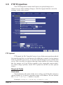
3.6 Date/Time Properties
The Date/Time Properties allow you to set the date and time in the
Express server. After making changes, click the Apply button to save the
settings in the video server.
Setting the Date and Time
Automatic vs. Manual - For the most accurate date & time, having
the camera automatically synchronize with a network time server is
recommended.
Automatic Time Set
When Automatic time synchronization is enabled, the camera will
query a network time server and synchronize the camera’s date and time,
usually accurate to within seconds or less. This will happen every time the
camera is powered on or rebooted, provided it is connected to the Internet
or a network with a time server.
•
Time Server - The name (or IP address) of a time server is entered
here. Some popular ones include:
pool.ntp.org
tock.usno.navy.mil
time-b.nist.gov
Note: While these time servers have proved reliable over the years,
there is no guarantee that they will always be available to the public.
Page 22
Express Video Servers
Manual Time Set
If you don’t have access to a time server, you can manually set the
video server’s clock. You can do this in one of two ways. Using the Sync
button, you can synchronize the Express server's clock to your PC’s clock.
You may also manually modify the time and date in the Date/Time box. In
either case, be sure to hit the Apply button after you’ve set the time.
TIME ZONE
The Express server integrates your current time zone into the time/
date string and can even automatically adjust for daylight savings time.
Type in the time zone code from the list on this page. If your time zone
is not listed, enter your abbreviated time zone followed by the number of
hours you are behind GMT (if you’re ahead of GMT, add the “-” character
before the value).
HST10
Hawaiian Standard Time
YST9YDT
Yukon Standard/Daylight Time (Alaska, parts)
MST7MDT
Mountain Standard/Daylight Time
CST6CDT
Central Standard/Daylight Time
AST4ADT
Atlantic Standard/Daylight Time
WET0WETDST
Western European Standard/Daylight Time
MEZ-1MESZ
Mitteleuropaeische Zeit/Sommerzeit
SAST-2SADT
South African Standard/Daylight Time
WST-8:00
Australian Western Standard Time
CST-9:30CDT
Australian Central Standard/Daylight Time
EST-10EDT
Australian Eastern Standard/Daylight Time
AT10ADT
Aleutian Standard/Daylight Time (Alaska, parts)
PST8PDT
Pacific Standard/Daylight Time
MST7
Mountain Standard Time (Arizona)
EST5EDT
Eastern Standard/Daylight Time
NST3:30NDT
Newfoundland Standard/Daylight Time
PWT0PST
Portuguese Winter/Summer Time
MET-2METDST
Middle European Standard/Daylight Time
JST-9
Japan Standard Time
CST-9:30
Australian Central Standard Time
EST-10
Australian Eastern Standard Time
NZST-12NZDT
New Zealand Standard/Daylight Time
Express Video Servers
Page 23
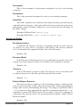
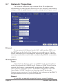
3.7 Network Properties
The Network Properties page contains all the IP configuration
information for setting up the Express server on a network. After making
changes, click the Apply button to save the settings in the Express server.
Ethernet
If your network is Ethernet-based (LAN, cable modem, DSL), use
the NET port on the back of the Express to access the server. The first
step to network access is assigning the Express an IP address. There are
two ways in which this can be done: automatically (DHCP) or manually
(static).
IP Assignment
DHCP
By default, the Express comes up in DHCP mode, meaning that it
probes the network for a DHCP server. If there is a DHCP server on the
network, the Express is automatically assigned an IP address, subnet
mask, gateway, and name servers. No manual configuration is needed.
One negative of DHCP mode is not knowing what IP address the
Express server was given. Use the StarDot Tools software to find DHCPassigned StarDot servers on your local network.
Manual
If you'd like to manually assign the Express a static IP address,
Page 24
Express Video Servers
set the Express to Manual IP Assignment and provide the following
information:
•
•
•
IP Address - The IP address you'd like to assign to the Express.
Consult your network administrator to determine what IP address
is OK to use. If you are setting up the Express behind a residential
gateway or cable/DSL router, your IP address will be something
similar to 192.168.1.5.
Subnet Mask - Find out your netmask from your network
administrator. If you're on a private network, your netmask will
usually be 255.255.255.0.
MAC Address - This is the factory-set Ethernet address of the
Express server. It also serves as the Server Serial ID. It cannot be
changed from the web menu.
Network
Hostname
Alphanumeric name of the Express that can get linked to the Express
video server's IP address. This is disabled if DHCP is enabled.
Default: expressxl
Gateway
In most cases, this is a machine name or IP address that serves as
a gateway to the Internet. If the Express is on a private network behind
a router/gateway, you would enter the IP address of the router/gateway.
This is disabled if DHCP is enabled.
Name Servers
DNS
This is the domain name server’s IP address. This is critical if your
FTP server and/or time server is entered as a domain name and not an IP
address. Check with your ISP to determine your name servers (you can
list up to three). This is disabled if DHCP is enabled.
Web Server
The Express server has a built-in web server which is used to serve
both the live image and configuration pages.
Web Server Port
In most situations you will want to leave the web server port at
its default value of 80. The only situation that calls for changing the
port number is if you're hosting one or more Express servers behind a
residential router/gateway that supports port forwarding.
Express Video Servers
Page 25
This allows you to access multiple Express Servers behind a single
public IP address (most DSL and Cable Modem accounts provide only
one public IP address).
Many routers can be configured to forward unique port numbers to
individual IP addresses on the private network side of the gateway.
Example: Assign the Express server a web server port of 8085. In your router, under the port forwarding section, route port 8085 to the Express server’s
IP address.
Use caution when changing the web server port number. If it's anything but 80, you will not be able to access it normally through a browser.
You will always need to add <:port number> to the end of the IP
address (Example: http://192.168.1.5:8085 from the local
network or http://208.146.196.41:8085 on the Internet).
Default: 80
Video Streaming Support
One way the browser or NVR software can pull the motion JPEG
stream from the camera is using each camera's unique streaming port. If
you want to disable this non-password port for security reasons, set the
port to 0. Most NVRs can read the motion JPEG stream without using
this open port.
Page 26
Express Video Servers
3.8 Dial-Out Properties
The Dial-Out Properties page contains all the ISP dial-up
configuration information for setting up the Express connected to an
analog modem. After making changes, click the Apply button to save the
settings in the Express server.
INTERNET DIAL-OUT CONNECTION (PPP)
If the Express server's primary connection to the Internet will be
a dial-up modem connection to the Internet, enter your ISP (Internet
Service Provider) account information here.
Check this option on if you'd like the Express to use an external
analog modem to dial the Internet.
Baud Rate
This represents the speed or baud rate at which the Express will
communicate with the external analog modem. For most dial-up
accounts, a baud rate of 38400 or 19200 works best.
Initialization String
This is a string that configures the analog modem before dialing the
Internet. The default string works fine in most cases.
Default: AT&F
Express Video Servers
Page 27
Phone Number
The phone number of the ISP (Internet Service Provider). You can
embed special characters in the phone number.
, = pause one second
# = same as # button on phone
* = same as * button on phone
Timeout
The Express will attempt to dial up the ISP for the specified number
of seconds. If the Express is unable to connect during this time period, it
will stop and start over again.
Default: 180
Username
The username or login assigned to you by your ISP.
Password
The password assigned to you by your ISP.
Default Connection
Enabling this option makes the ISP dial-out connection the
Express 1's default connection to the Internet.
Default: On
Always Up
If enabled, the Express will attempt to stay continuously connected
to the Internet. If disconnected, it will automatically attempt to reconnect.
If the Express is configured to upload images to a server via FTP, it is not
necessary to enable this option; the Express will automatically attempt to
dial into the Internet when an image is scheduled to upload if dial-out is
enabled.
Default: Off
Send CR After Login
This advanced ISP option tells the Express to send a CR (Carriage
Return) after logging in. Most ISP's don't require this, but some do.
Default: Off
Shell Login
This advanced ISP option tells the Express to perform a shell login.
Most ISP's don't require this, but some do.
Default: Off
Page 28
Express Video Servers
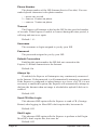
3.9 Security Properties
The Security properties page contains user/password
information for securing the Express server from unwanted visitors.
Express Users
The Express server has its own multi-user capable, password
protected operating system. By default, the live images can be viewed
by anyone and only the configuration pages are password protected.
However, these options can be changed.
admin - The admin user has configuration and viewing rights. It is
strongly recommended that you change the default password
(initially “admin”) to something else. This will prevent anonymous
users from logging into the camera and making changes. It is
important to choose your password carefully. Pick something that
cannot easily be guessed. The password can be a combination of
alpha and numeric characters, upper and lowercase (maximum 8
characters).
Tip: Do not use the same password you use on another system or anything
that can be easily guessed. At the same time, do not forget or lose your
password or you will not be able to access the Express configurationmenus without resetting the unit to its default settings.
viewer - The viewer user only has viewing rights (this user cannot
access the configuration menus). By default, the viewer user has no
password. This allows anyone to view the images on the camera
without being prompted for a password. If you want to block public
access to the live image, you will need to change the password for
the viewer user.
Express Video Servers
Page 29
To modify the password of an existing user, click on the user name
and then type in a new password in the password field (retype it in
the verify password field). Then click the Add/Modify button.
Adding a New User
To add a user to the Users list, type in the desired username in the
Name field. Type and retype a password in the Password fields. Click the
Add/Modify button. New users will only have viewing rights; only the
admin user can make configuration changes in the Express server.
Deleting a User
To remove a user from the Users list, click on the desired username
and click on the Remove button. Note: The default users, admin and
viewer, cannot be removed.
3.10 Advanced Menus
The advanced menu allows you to configure some advanced features
inside the video server such as triggers and dynamic DNS support.
3.11 Miscellaneous
Reboot Camera
Click this to reboot the video server.
Upgrade Firmware
Allows you to select a new firmware and upgrade the video server.
You can also use the StarDot Tools software to upgrade the firmware. It is
recommended that you clear the configuration settings before upgrading
(see the manual config section).
3.12 Manual Config
Configuration Files
This advanced menu provides access to all of the internal
configuration files. We recommend that you do not edit these files unless
you are well versed in Linux and the Express server settings.
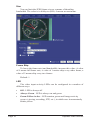
3.13 Pan/Tilt/Zoom Functions
To use a pan/tilt/zoom camera with the Express server, you must
select a compatible model from the PTZ configuration menu. You may
need an RS-232 to RS-485 converter to control certain PTZ cameras.
This PTZ menu seen here will appear on the main viewing page of
the Express server.
Page 30
Express Video Servers
Tilt/Pan
Controls the Pan/Tilt movements of the camera.
Focus
Allows user to manually focus the camera. For a single increase or
decrease of focus, you must click the arrows at each end of the focus
control panel. If a greater amount of increase or decrease is desired, you
will need to click on the varying bars located in the center of the focus
control panel.
Iris
Allows user to manually control the open and close functions of the
iris. For a single increase or decrease of iris, you must click the arrows
at each end of the iris control panel. If a greater amount of increase or
decrease is desired, you will need to click on the varying bars located in
the center of the iris control panel.
Zoom
Allows user to manually zoom in and out. For a single increase or
decrease in zoom, you must click the arrows at each end of the zoom
control panel. If a greater amount of increase or decrease is desired, you
will need to click on the varying bars located in the center of the zoom
control panel.
Presets
This option allows the user to preset a focal point into the
Express server's memory. The number of available preset focal points
depends on the model of the PTZ camera.
To set a preset focal point use the pan/tilt controls and zoom controls
until you have your desired focus point. Then using the drop down list
select the desired number for that preset, and click the "Set" button. This
will save your focal point into memory.
Express Video Servers
Page 31
3.14 Dynamic DNS
If the Express server is behind a DSL or cable modem connection
and the public IP address changes, you can use tzo.com as a dynamic
DNS service. This maps your dynamic (temporary) IP address to a static
(permanent) hostname of your choice (i.e. yourcompany.stardotcams.com
or yourname.remotecam.com).
Why is knowing your public IP address valuable? If your router is
configured to “port forward” port 80 to the camera’s local IP address, you
can browse to the camera directly from anywhere on the Internet. This is
useful for viewing the camera live and making configuration changes from a
remote location. For information on configuring port forwarding on a router,
visit http://www.portforward.com, click on routers, select your model and
click on “Default guide”.
To set up a TZO account, visit http://stardot.tzo.com. After you’ve
signed up, enter the appropriate information in either NetCam SC or your
router (if it supports DDNS).
Page 32
Express Video Servers
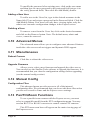
3.15 Trigger Properties
The trigger menu allows you set up the video server to capture and
upload a series of images based on a triggered event using the input ports
on the back of the video server.
Trigger Overview
By connecting an alarm system, motion detector or other type of
sensor to the back of the Express server, it is possible to gather a series of
images when the sensor “triggers” the video server. Wiring examples can
be found at the end of this chapter.
EXTERNAL TRIGGER
I/O Port
Select with I/O port your trigger source is connected to.
Express Video Servers
Page 33
I/O Level
Select the state of your trigger source’s output.
SCHEDULE
The server can wait in trigger-capture/upload mode 24 hours a day,
seven days a week, or you can set whatever time window and days of the
week you like. Use military time for the beginning and ending window
times.
Example: You can configure the server to only upload Between
07:30 and 18:30 only on Mon, Tue, Wed, Thu and Fri.
PRE-BUFFER
Pre-buffered images are images that are stored before the event
trigger occurs. For example, if you connect a door sensor to the server
with 10 image pre-buffering enabled, 10 frames of video that occurred
before the door was opened will be captured/uploaded.
If pre-buffering is enabled, the server will continuously buffer
images in a rotating loop. This will affect the video frame rate if you’d
like to view live streams at the same time. Most applications don’t
require pre-buffering. Only enable this option if you require video frames
before the actual trigger takes place.
Delay
The number of milliseconds to delay between image captures. For
the fastest possible frame rate, set this to 0. Viewing other video sources
during the triggered capture will affect the recording speed. Assuming no
other video sources are being viewed/uploaded, here are some example
frames rates for a single triggered video source:
0 ms = Max Speed (10 frames per second)
250 ms = 4 FPS
1000 ms = 1 FPS
Count
The number of pre-buffer images to store. There is a finite amount
of memory in which to store images. Keep the total number of pre and
post-buffer medium resolution images to below 100, even less for full
size images.
POST-BUFFER
Post-buffered images are images that are recorded after a triggered
event occurs. For example, if you connect a door sensor to the server
with 20 image post-buffering enabled, 20 images will be captured/
uploaded after the door opened.
Page 34
Express Video Servers
Delay
The number of milliseconds to delay between image captures. For
the fastest possible frame rate, set this to 0. Viewing other video sources
during the triggered capture will affect the recording speed. Assuming no
other video sources are being viewed/uploaded, here are some example
frames rates for a single triggered video source:
0 ms = Max Speed
250 ms = 4 FPS (frames per second)
1000 ms = 1 FPS
Count
The number of post-buffer images to store. There is a finite amount
of memory in which to store images. Keep the total number of pre and
post-buffer medium resolution images to below 100, even less for full
size images.
UPLOAD VIA FTP
If you’d like the event-triggered image captures to be uploaded to
an FTP server, select this option. The “Upload via FTP” parameters are
independent of the regular image FTP parameters (see Chapter 3.5).
Hostname
The hostname is the name of the server where you'd like the
video server to upload images. It can be a machine name or an IP
address. Do not include the http:// or ftp:// header or a path.
Example: example.com or ftp.example.com
Username
This is the username or login name assigned to you by your hosting
provider.
Password
This is the password assigned to you by your hosting provider
Path
Specify the path on your FTP server where you’d like the images
stored. There is no need to specify a filename. The video server
automatically creates sequential filenames (image0-000.jpg, image0-001.
jpg, image0-002.jpg, where image0 means images from the first video
input).
Express Video Servers
Page 35
Passive Mode
If the Express is behind a proxy server, enable passive mode. If
you are unsure if you need passive mode, it is usually safe to enable it
anyway.
Default: On
Timeout
If the FTP process hasn’t completed within the time specified here,
the Express will attempt to restart the process.
Default: 120
UPLOAD VIA SMTP (EMAIL)
If you prefer the event-triggered image captures to be e-mailed,
select this option. If you’ve enabled a large number of images, this can
add up to a large e-mail attachment.
Mail To
Email address where images are to be sent.
Mail From
Specify a “from” e-mail address. This can be made up.
3.16 Trigger Sensor Connection
Express 2
1
Opto-Isolated Trigger Input 1-A
2
Opto-Isolated Trigger Input 1-B
3
Relay 1-A
4
Relay 1-B
The Express 2 I/O connector contains one opto-isolated trigger input
and one relay connection.
Pins 1 and 2 are the opto-isolated input, providing 2500VRMS
isolation. To trigger, apply positive voltage to pin 1 and apply negative
or ground to pin 2. The trigger voltage should be 3.5VDC to 12VDC,
1.4mA minimum. You may connect directly to a 12VDC alarm system,
current-providing door sensor, etc. but the polarity must be correct or
you risk the possibility of false triggers. Sensors such as simple open/
closed switches cannot be used without a pull-up voltage to provide the
[email protected] minimum.
Pins 3 and 4 are the relay, which can handle 2A @ 28VDC. It is
Page 36
Express Video Servers
good for 100,000 cycles at maximum load, 100 million when unloaded.
The relay is rated for 0.5A @ 125VAC; however it should never be
used to directly control AC voltages from the wall outlet. It will wear
out rapidly and may result in sparking with risk of fire. Switching
mechanisms designed for controlling wall outlet power, which can be
triggered from a low DC voltage, are available.
Express 4/8
1
Relay 1-A
2
Relay 1-B
3
Trigger Input 1 (+5V pull-up)
4
Trigger Input 2 (+5V pull-up)
5
Trigger Input 3 (+/- 64V OK)
6, 7
Future Use
8
Ground (“Common” for Trigger Inputs)
The Express 4 and 8 I/O connector contains three non-isolated
trigger inputs and one relay connection.
Pins 3 and 4 are trigger inputs 1 and 2, both of which have a 5v
pull-up. Trigger input 1 and 2’s pull- ups can be shorted to the ground
pin (also present on the connector) to provide a second state. A normal
operation might be a magnetic switch on a window or door which is
normally closed, and which is broken when the door is opened, giving
the trigger signal.
Pin 5 is a diode-clamped trigger which can accept +-64V as its input,
with negative voltages generating an internal “0” condition, and anything
over +3V generating a “1” condition.
Pins 1 and 2 are the relay, which can handle 2A @ 28VDC. It is
good for 100,000 cycles at maximum load, 100 million when unloaded.
The relay is rated for 0.5A @ 125VAC; however it should never be
used to directly control AC voltages from the wall outlet. It will wear
out rapidly and may result in sparking with risk of fire. Switching
mechanisms designed for controlling wall outlet power, which can be
triggered from a low DC voltage, are available.
Express Video Servers
Page 37
Troubleshooting Guide
The StarDot Tools software doesn't list the Express server on my local network and/or is not accessible via its IP address.
1. Double check all cable connections and make sure the Express server's
network cable is plugged into an active Ethernet hub, switch or router.
Make sure the Express server's power LED is on.
2. Connect the Express server to a PC's serial port with the included null
modem cable to verify network settings with the StarDot Tools software.
The Express is slow to respond on a web browser.
1. Set the JPEG quality to 70 or below. The higher the JPEG quality, the
bigger the image file size, with very little improvement in image quality.
Images are not uploading to FTP server.
1. Double check all settings including hostname, username, password and
path by using third party FTP client software (the command prompt FTP
in Windows is a good test).
2. Try using an IP address in the hostname, or double check your DNS settings. For a dial-up Express, do not use an IP address for the hostname.
3. Try turning on the advanced FTP options “Delete Before Rename” and
“IIS 4.0”
4. Telnet into the Express server type ftpscript ftp0.scr and press
Enter. Watch the results for errors. (Note: To telnet from windows, click
on Start, Run and type telnet <express_IP_address> and click OK.
Technical Support
Technical support for StarDot customers is available directly from
StarDot Technologies. Answers to most questions can be found at our
web site at http://www.stardot.com.
Technical Support and Software/Firmware Downloads
http://www.stardot.com/kb
Technical Support via E-mail
[email protected]
Technical Support via Phone
(714) 908-2380, 6AM - 5PM PST, Monday-Friday
Page 38
Express Video Servers
Express Video Servers
Page 39
Specifications
TECHNICAL SPECS: Express 2, 4 and 8
Image Compression
Frame Rate
Resolution
Video Input
Video Decoder
Network Connection
Network Protocols
I/O Connectors
Internal Operating
System
Security
Operating Temperature
Physical
EMI Approval
Power Requirements
Page 40
Industry Standard JPEG, M-JPEG
Express 2: 1 x 30 FPS D1 or 2 x 5 FPS D1
Express 4: 4 x 30 FPS D1
Express 8: 8 x 7.5 FPS
NTSC: 704x480, 352x240, 176x120
PAL: 704x576, 352x288, 172x144
Express 2: 2 x BNC (dual input or looping output)
or 1 x S-Video
Express 4: 4 x BNC inputs and 4 x BNC looping outputs
Express 8: 8 x BNC inputs
All BNC inputs are composite video signal w/75 ohm
termination.
Adaptive 2/4-line comb filter for two dimensional chrominance/
luminance separation resulting in increased luminance and
chrominance bandwidth for all PAL and NTSC standards as
well as reduced cross color and cross luminance artifacts
1 x 100-baseT Ethernet (10/100 compatible)
TCP/IP, HTTP, FTP, DHCP, ARP, PING, TELNET, DAYTIME,
NTP, SMB, NFS, SMTP, PPP
Express 2:
1 x Fully Isolated Digital Alarm Inputs
1 x Fully Isolated Relay, 28VDC 2A / 125VDC 0.5A
Express 4/8:
3 x Digital Alarm Input
1 x Fully Isolated Relay, 28VDC 2A / 125VDC 0.5A
uClinux
Separate password-protected user accounts for configuring the
server and viewing the images, additional user account can be
added.
-40°F to +120°F (-40°C to +49°C)
Express 2:
Size: 3.6” W (92 mm) x 1.7” H (44 mm) x 6.0” D (152 mm),
Weight: 13 oz (369 grams)
Express 4/8:
Size: 9.3” W (235 mm) x 1.8” H (45 mm) x 5.8” D (147 mm),
Weight: 13 oz (369 grams)
FCC Class A, CE (EN55024/1998, EN5022/1998)
12VDC 1A
Express Video Servers
FCC STATEMENT OF COMPLIANCE
This equipment has been tested and found to comply with the limits for a Class A
digital device, pursuant to Part 15 of the FCC Rules. These limits are designed to
provide reasonable protection against harmful interference when the equipment is
operated in a commercial environment. This equipment generates, uses, and can
radiate radio frequency energy and, if not installed and used in accordance with the
instruction manual, may cause harmful interference to radio communications. Operation of this equipment in a residential area is likely to cause harmful interference in
which case the user will be required to correct the interference at his own expense.
Express Video Servers
Page 41
Notes
Page 42
Express Video Servers
Express Video Servers
Page 43
6820-H Orangethorpe Ave
Buena Park, CA 90620 U.S.A.
714-908-2380 • Fax: 714-844-4336
E-mail: [email protected]
http://www.stardot.com
© Copyright StarDot Technologies
express video servers manual 05-25-10.indd


![Front End Risk Adjustment System [ FERAS ] User](http://vs1.manualzilla.com/store/data/005730281_1-6f4c2bdb0bfee36132bd7754fa830eb4-150x150.png)