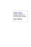
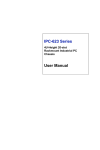
1
ACP-5260
Fault Resilient Chassis
User’s Manual
Copyright
Advantech Co., Ltd copyrights this documentation and the software included with this
product in 2003. All rights are reserved. Advantech Co., Ltd. reserves the right to make
improvements in the products described in this manual at any time without notice.
No part of this manual may be reproduced, copied, translated or transmitted in any form or
by any means without the prior written permission of Advantech Co., Ltd. Information
provided in this manual is intended to be accurate and reliable. However, Advantech Co.,
Ltd. assumes no responsibility for its use, or for any infringements of the rights of third
parties, which may result from its use.
Acknowledgments
IBM and PC are trademarks of International Business Machines Corporation. MS-DOS,
Windows are trademarks of Microsoft Corporation. Intel and Pentium are trademarks of
Intel Corporation.
On-line Technical Support
For technical support and service, please visit our support website at:
http://www.advantech.com/support
Note:
DDDDDDDDDDDDDDDDDDDDDDDDDDDDDDDDDDDDDDDD
DDDDDDDDDDDDDDDDDDDDDDDDDDDDDDDDDDDDDDDD
DDDDDDDDDDDDDDDDDDDDDDDDDDDDDDDDDDDDDDDD
DDDDDDDDDDDDDDDDDDDDDDDDDDDDDDDDDDDDDDDD
DDDD
Part No. 2 0 0 2 5 2 6 0 0 0 1st Edition
Printed in Taiwan
Apr 2003
ii
ACP-5260 User’s Manual
iii
Contents
CHAPTER 1 GENERAL INFORMATION ..............................................8
1.1
1.2
1.3
1.4
1.5
1.6
1.7
INTRODUCTION........................................................................ 8
SPECIFICATION ........................................................................ 8
Table 1.1: Specification..............................................8
PASSIVE BACKPLANE OPTIONS............................................. 9
Table 1.2: Passive Backplane Options.....................9
POWER SUPPLY OPTIONS....................................................... 9
Table 1.3: Power Supply Options.............................9
SYSTEM REGULATION.......................................................... 10
Table 1.4: System Regulation..................................10
DIMENSION DIAGRAM.......................................................... 10
Figure 1-1: Dimention Diagram.............................10
EXPLODED DIAGRAM........................................................... 11
Figure 1-2: Dimension Diagram............................11
CHAPTER 2 SYSTEM SET UP ..................................................................13
2.1 SYSTEM INSTALLATION ....................................................... 13
2.1.1 A TTACHING THE HANDLES .................................................. 13
2.1.2 REMOVING THE TOP COVER................................................. 13
2.1.3 CHASSIS FRONT AND REAR SECTIONS............................... 13
Figure 2-1 Front Panel Section...............................13
2.1.4 SYSTEM RESET ...................................................................... 13
2.1.5 A LARM RESET SWITCH........................................................ 14
2.1.6 M OMENTARY SWITCH.......................................................... 14
2.1.7 USB CONNECTOR ................................................................. 14
2.1.8 PS/2 CONNECTOR.................................................................. 14
2.1.9 REAR BEZEL SECTION.......................................................... 14
Figure 2-2 Rear Bezel Section.................................14
2.1.10 DRIVE BAY & SCSI STORAGE INSTALLATION .............. 15
Figure 2-3: Driver Bay and SCSI storage.............15
2.1.11 CPU CARD AND A DD-ON CARDS INSTALL..................... 15
2.1.12 ACP-5260BP-46R ............................................................. 16
2.1.13 ACP-5260MB-46R............................................................ 16
iv
ACP-5260 User’s Manual
2.2
SYSTEM LED INDICATORS.................................................. 17
Table 2.1: System Status LED..................................17
2.2.1 SYSTEM POWER LED ........................................................... 17
Table: 2.2: System Power LED ...............................17
2.3 SCSI STORAGE...................................................................... 18
2.3.1 RAID SYSTEM INSTALLATION ........................................... 18
Table 2.3: HDD PWR LED and Status LED.........19
2.3.2 CABLING OF SCSI STORAGE ............................................... 19
Figure 2-4: Cabling of SCSI Storage.....................19
2.4 COOLING FAN & FILTER...................................................... 19
CHAPTER 3 ALARM BOARD ...............................................................22
3.1
ALARM BOARD LAYOUT....................................................... 22
Figure 3-1: Alarm Board Layout............................22
3.2 ALARM BOARD SPECIFICATION........................................... 22
3.2.1 INPUT SIGNALS...................................................................... 22
3.2.2 OUTPUT SIGNALS.................................................................. 23
3.2.3 OTHER INTERFACES.............................................................. 23
3.2.4 PIN DEFINITION OF A LARM BOARD ................................... 23
Table 3-1: CN1: Ext Pwr, mini 4 Pin conn............23
Table 3-2: CN2 10/100M LAN Connector.............23
Table 3-3: CN4 : I2C Sensor (LM75) Conn..........24
Table 3-4: CN8 : RS-232 Connector......................24
Table 3-5: CN10 : LCM Display Board Conn......24
Table 3-6: CN11:SNMP-1K Dhtr Bd Conn (L) ....24
Table 3-7: CN12:SNMP-1K Dhtr Bd Conn (R)....25
Table 3-8: CN13 : Voltage Detect Input Conn......26
Table 3-9: CN16 : 4 bit Power Good Input...........26
Table 3-10: CN17 : Alarm Reset.............................26
Table 3-11: CN18 : LED Board Connector...........26
Table 3-12: CN19:Conn bank from CPU card .....27
Table 3-13: CN20 : Connector bank to Chassis...27
Table 3-14: J1 : External Speaker..........................27
3.3 SWITCH 1 & FAN NUMBER SETTINGS................................ 27
Table 3.15: Switch 1 for Fan Number Settings.....27
3.4 THERMAL SENSOR, LED, USB AND K/B ......................... 27
3.2.5 PIN DEFINITION OF THERMAL SENSOR ............................... 27
Table 3.16: CN1/2: I2C Sensor (LM75) Conn......27
Figure 3-2: Thermal Sensor Layout.......................28
v
3.2.6 PIN DEFINITION OF LED INDICATOR ................................. 28
Table 3.17: CN1: LED Board Connector..............28
Figure 3-3: LED Layout...........................................28
3.2.7 PIN DEF OF USB, PS/2 KB INTERFACE BOARD ................ 29
Table 3.18: CN1 ~ CN4 Pin Definition..................29
Figure 3-4: USB, PS/2 KB Layout..........................29
CHAPTER 4 SCSI STORAGE................................................................32
4.1
6- SLOT SCA-2 80-PIN BP LAYOUT.................................... 32
Figure 4-1: SCA Backplane Layout........................32
4.1.1 PIN DEFINITION OF SCA BACKPLAN .................................. 32
Table 4.1: J1: Terminator Enable/Disable............32
Table 4.2: J2: SAF-TE Chip ID Selection .............32
Table 4.3: J3/J4: SAF-TE Enable/Disable............32
Table 4.4: JP1: HDD Spin up Option ....................33
Table 4.5: JP2~ JP4..................................................33
Table 4.6: JP5 ............................................................33
Table 4.7: SW1, SW2, CON 7, CON 8 ...................33
4.2 SAF-TE.................................................................................. 33
4.3 RAID...................................................................................... 34
APPENDIX A SAFETY INSTRUCTIONS ..........................................36
A1
SAFETY INSTRUCTIONS ........................................................ 36
vi
ACP-5260 User’s Manual
CHAPTER
1
General Information
Chapter 1 General Information
1.1 Introduction
ACP-5260 is a high performance, high capacity-computing platform
which meets a variety of needs including filing, printing, applications,
e-mails and Web serving. This powerful computing server includes a
full Disk Array storage of high availability features for minimizing
the system downtime especially in mission-critical computer
telephony application, industrial automation and factory management.
A wide range of standard computing peripherals can be integrated
with the chassis to meet different application development under
mission-critical environment 24 hours a day, 7 days a week.
1.2 Specification
Table 1.1: Specification
Drive Bay
RAID
Cooling
3.5”
5.25”
Slim CD-ROM
Level
Auto Rebuilding
Fan
Miscellaneous Rear panel
Environment
Temperature
Humidity
Vibration (5-500 Hz)
Shock
Acoustic Noise
Front-accessible
Internal
6(hot-swap), 1
1
1
1
By RAID card
Yes
Dual (46 CFM/each) for SCSI storage
Three (114 CFM/each) on middle
Two high pressure browser
(25.4 CFM/each) on rear
Two D-SUB 9-pin brackets
Dual AC Inlet
Operating
Non-Operating
0 ~ 40 ºC (32 ~ 104 ºF)
-40 ~ 60 ºC (-40 ~
140 ºF)
10 ~ 95%@40ºC,
10 ~ 95 %@40ºC,
non-condensing
non-condensing
1 Grms
2G
10 G(With 11 msec duration,
30G
1/2 sine wave)
Less than 52dB sound pressure at
5~28ºC (41~82ºF)
8
ACP-5260 User’s Manual
Physical
Compliance
Altitude
Dimensions (W x H x D)
Weight
Safety
0 to 3048 m (0 ~ 10,000 ft)
482 x 222 x 660 mm (19” x 8.75” x 26”)
30 kg (66 lb)
CE compliant, UL/cUL approved
1.3 Passive Backplane Options
Table 1.2: Passive Backplane Options
B/P Model Name
Slot per Segment(ISA/PCI/CPU)
Segment
PCA-6120-0B1
20 ISA
1
PCA-6120P4-0B1
15 ISA/4 PCI/1 CPU
1
PCA-6119P7-0B1
11 ISA/7 PCI/1 CPU
1
PCA-6120P12-0A1
8 ISA/12 PCI/ 1 CPU
1
PCA-6119P17-0B1
1 ISA/17 PCI/ 1 CPU
1
PCA-6120P18-0A1
1 ISA/18 PCI/1 CPU
1
1.4 Power Supply Options
Table 1.3: Power Supply Options
Model Name
Watt
1757946005
460W
(for BP version) ATX,
PFC
1757946006
460W
(for MB version) ATX,
PFC
Input
Safety &
MTBF
Output
Mini-load
100 ~ 240 Vac +5V@ 40A
(Full-range)
+3.3V@30A
+12V@27A
-12V@1A
[email protected]
+5Vsb@2A
100 ~ 240 Vac +5V@ 40A
(Full-range)
+3.3V@30A
+12V@27A
-12V@1A
[email protected]
+5Vsb@2A
+5 V @ 5 A
+3.3 V @ 1A
+12 V @ 2.5 A
[email protected]
UL/CSA/TUV
/CCC
148,000
hours@25
(Full load)
+5 V @ 5 A
+3.3 V @ 1A
+12 V @ 2.5 A
[email protected]
UL/CSA/TUV
/CCC
148,000
hours@25
(Full load)
9
1.5 System Regulation
Table 1.4: System Regulation
Model Name
With Power Supply
With Backplane
Regulation
ACP-5260BP-40RZ
1757946005
W/O
UL,cUL,CE
ACP-5260MB-40RZ
1757946006
W/O
UL,cUL,CE
1.6 Dimension Diagram
Figure 1-1: Dimention Diagram
10
ACP-5260 User’s Manual
1.7 Exploded Diagram
Figure 1-2: Dimension Diagram
11
CHAPTER
2
System Setup
12
ACP-5260 User’s Manual
Chapter 2 System Setup
2.1 System Installation
2.1.1 Attaching the handles
The handles for the front panel are in the accessory box. To install the
handles, simply secure them to the front panel with the provided screws.
2.1.2 Removing the top cover
First, remove the chassis cover. There are two parts of top cover, one is
located on front, and another is located on rear. The front top cover is
fixed to the chassis by two screws on both sides. The rear top cover is
fixed to the chassis by three screws on both sides.
2.1.3 Chassis Front and Rear Sections
The front panel switches and I/O behind the door are used for system
power, system reset, alarm reset, USB and PS/2 keyboard. A
multi-function key lock locks the door cover; user could lock the door
cover by key or without key.
Figure 2-1 Front Panel Section
2.1.4 System Reset
Press this switch to reinitialize the system. This is the same as the
hardware reset button.
13
2.1.5 Alarm Reset Switch
Press this switch to suppress or stop an audible alarm. Whenever a fault
in the system occurs (e.g. fan failure, rising chassis temperature,
backplane voltage problem), an audible alarm is activated. Pressing this
switch will cause the alarm to stop.
2.1.6 Momentary Switch
Use this switch and by way of ATX (PS_ON) function to turn on system
ATX power.
Please use system shutdown to turn off system power automatic or press
momentary switch for a while to turn off system power
2.1.7 USB connector
If you want to connect any USB interface device to the system, you could
use this connector.
2.1.8 PS/2 connector
If you are using PS/2 type keyboard, you could use this connector to
connect with your keyboard
2.1.9 Rear Bezel Section
The rear section of B/P version includes B/P rear window, 20-slot I/O
brackets and dual AC inlets for connecting with power cord.
The rear section of M/B version includes M/B rear window, 7-slot I/O
brackets, ATX M/B I/O cover, others are same as B/P version.
Figure 2-2 Rear Bezel Section
14
ACP-5260 User’s Manual
2.1.10 Drive Bay & SCSI Storage Installation
The standard drive bay of the ACP-5260 can hold one slim type
CD-ROM, one 5.25” and one 3.5” device disk driver. The location of
slim type CD-ROM and one 5.25” is on the top of SCIS storage.
a. Remove the front top cover
b. Release two screws of FDD holder first; release four screws of
storage cushion and them move storage until you have enough space
to take the storage enclosure out from ACP-5260 chassis.
c. Lift off the two power cable which are from system power
d. Insert the drives into their proper locations in the drive bay and secure
them with the screws provided.
e. Connect the disk drive power and signal cables.
Figure 2-3: Driver Bay and SCSI storage
The SCSI storage holds six 3.5” mobile drawer which is for 1” height
SCSI SCA-2 80-pin 3.5” HDD, and with 6-slot SCA backplane. User
could install 1” height SCSI SCA-2 80-pin 3.5” HDD into this SCSI
storage and use RAID card to complete a RAID system for ACP-5260.
2.1.11 CPU Card and Add-on Cards Install
a.
Open the rear top cover and move aside the cardholder, dual
browsers by four screws
b.
Find out the location of PICMG slot, take out I/O bracket first,
and install SBC(CPU card)
c.
Connect the 5Vsb and PS_ON cable of power supply to SBC.
Find the location of PCI or ISA slot, take out the I/O bracket first, and
15
install add-on card.
After the CPU card and all add-on cards to be installed, fix them tightly
with backplane holder by screw and fix them well by cardholder.
2.1.12 ACP-5260BP-46R
ACP-5260BP-46R has a momentary switch on the front panel. It is
20-slot backplane version but without backplane and with a front
hot-swappable 460W redundant power supply inside.
2.1.13 ACP-5260MB -46R
ACP-5260MB-46R has a momentary switch on the front panel and is for
ATX M/B form factor. It is without motherboard and with a front
hot-swappable power supply inside.
Note:
There is several type of SCSI 3.5” HDD, when in doubt, consult with an
experienced technician before SCSI SCA-2 80-pin HDD installation.
a. Open the front door by turning the key lock.
b. Find the latch of 3.5” HDD mobile drawer and push it to the
up location.
c. Press down the handle of 3.5” HDD mobile drawer down
until the end, then hold the handle and draw it out.
d. Install 1” height SCSI SCA-2 80-pin 3.5” HDD by four
screws.
e. Return and push the mobile drawer within HDD toward to
the SCSI storage until the handle of mobile drawer is
moving up.
f. Push the handle of mobile drawer until the end, and then
press the latch to the down location.
Before starting the installation process, be sure to shut down all power
from the chassis. Do this by turning off the power switch, and
unplugging the power cord from the power outlet. When in doubt,
consult with an experienced technician.
16
ACP-5260 User’s Manual
2.2 System LED Indicators
Table 2.1: System Status LED
LED
Description
Red
PWR
HDD
TEMP
System Redundant Power
Hard Drive activity
Chassis Temperature
FAN
System Cooling Fans
Abnormal (RPS failure)
N/A
Abnormal (chassis
temperature is over default
50°C)
Abnormal (system cooling
fan failure)
Green or
Orange
Normal
Data access
Normal
Normal
When the PWR LED turns red, it indicates the redundant power supply is
failure. To stop the alarm buzzer, press the Alarm Reset button. Please
check out the redundant power supply right away and replace failure
power supply module, then PWR LED will turns green after replacement
with good one.
When the FAN LED turns red, it indicates the system cooling fan got
failure. An audible alarm is also activated. To stop the alarm buzzer,
press the Alarm Reset button then replace the fan immediately. FAN LED
will turns green if all of system cooling fans are working fine.
If the TEMP LED is red, the system detects rising temperature inside the
chassis. An audible alarm is activated. To stop the alarm buzzer, press
the Alarm Reset button. Inspect the system environment and fan filter
immediately. Make sure airflow inside the chassis is smooth and not
blocked by dust or other particles. If problem persists, consult an
experienced technician.
2.2.1 System Power LED
The Power Status LED indicates the status of the system power voltage
signals.
Table: 2.2: System Power LED
LED
+3.3V
+5V
Description
+3.3Voltage output
+ 5Voltage output
Light
Normal
Normal
17
No light
No output
No output
+12V
-5V
-12V
+12Voltage output
- 5Voltage output
-12Voltage out put
Normal
Normal
Normal
No output
No output
No output
When a LED fails to light, it indicates a problem with one of the voltage
output. An audible alarm is sounded. Check to make sure that the
power supply is working fine for each voltage output. If problem persists,
consult an experienced technician.
2.3 SCSI Storage
Note:
The SCSI storage is within the system data; please have to be very
carefully to avoid damage the system data if you have to take the SCSI
storage out from chassis. When in doubt, consult with an experienced
technician.
2.3.1 RAID System Installation
a.
b.
c.
d.
Open the front top cover and to find out the location of storage
enclosure. Please prepare a 68-pin U-160 SCSI cable before RAID
system installation.
This 68-pin U-160 SCSI cable, one end is connected with SCSI
storage of ACP-5260, the other end is connected with your SCSI
RAID card or SCSI RAID controller
If you are going to install SCSI RAID card, please install up to six
SCSI SCA-2 80pin HDD into SCSI storage of ACP-5260 and
follow up the RAID card instruction to implement your RAID
system. If you are going to install SCSI RAID controller please
install up to six SCSI SCA-2 80-pin HDD into SCSI storage of
ACP-5260 and follow up the SCSI RAID controller to implement
your RAID system.
Maybe you need an extra SCSI cable to connect between “external
SCSI connector of RAID card” and “other host”.
18
ACP-5260 User’s Manual
Table 2.3: HDD PWR LED and Status LED
LED
PWR
Description
Power of
HDD
Status
Hard Drive
activity
Green
Off for no HDD or
No System Power
On for with HDD
N/A
Blue
N/A
Red
N/A
Blue & Red
N/A
Data
access
HDD
failure
Data rebuild or
construction
2.3.2 Cabling of SCSI Storage
There are three power cables of power supply, one SCSI cable from
RAID card and two power cables of fan connected between this SCSI
storage and ACP-5260 system. Please do remember to plug out those
cable when you have to take out SCSI storage from ACP-5260 and to
plug in those cable well before you install SCSI storage into ACP-5260.
Figure 2-4: Cabling of SCSI Storage
2.4 Cooling Fan & Filter
There are seven system-cooling fans located inside ACP-5260. Two
cooling fan are for SCSI storage which we mentioned on chapter 2.3
already. Three are located on the middle of the chassis. Two are located
on the rear of chassis. Those cooling fans are very easy to maintain since
all of these five cooling fan are swappable.
When any one of cooling fan breaks down, the system sounds a
continuous alarm. To disable the alarm, press the Alarm Reset Switch on
the front panel and replace the failure fan immediately.
Behind the front door is with the filter. If the filter is blocked with dust or
other particles, please clean it or replace with a new filter.
19
CHAPTER
Alarm Board
3
Chapter 3 Alarm Board
The alarm board is located on the side of chassis. It gives an audible
alarm when:
a. Any power supply module of redundant power supply got failure.
b. Any one of the SCSI storage cooling fans and system cooling fans is
defective.
c. Temperature inside the chassis rises over 50°C(default setting).
d. A problem occurs in one of the power voltage output.
The detailed layout and specification of the alarm board are as follows:
3.1 Alarm board layout
Figure 3-1: Alarm Board Layout
3.2 Alarm board Specification
3.2.1 Input Signals
Ø
Ø
Ø
Ø
Ø
Input power +5V, +12V from CN1
7 FAN connectors (FAN1~FAN7, Pin 1: GND, Pin 2: +12V, Pin 3: FAN Signal)
One thermal board connector (CN4, it can connect up to 8 thermal boards in a roll)
One power good input (CN16)
One alarm reset input (CN17)
22
ACP-5260 User’s Manual
Ø
Ø
Ø
Ø
One voltage signal connector (CN13, connect from PSU or backplane, includes
±12V, ±5V, 3.3V)
One ATX power connector (CN19 connects from CPU card, CN20 connects to
chassis)
One system reset connector (CN 19 connect from CPU card, CN20 connects to
chassis)
One Hard Disk LED connector (CN19 connects from CPU card)
3.2.2 Output Signals
Ø
Ø
Ø
Ø
Ø
Ø
One LED board connector (CN18)
One LCM board connector (CN10)
SNMP daughter board connector (CN11 & CN12 connect to SNMP -1000 main
board)
One Buzzer output(J1)
ATX power switch connector (CN19 connects from CPU card, CN20 connects to
chassis)
System reset connector (CN 19 connect from CPU card, CN20 connects to chassis)
3.2.3 Other Interfaces
Ø
Ø
Ø
Ø
Ø
One pair of Watch dog input/output signals(CN20)
One pair of I2 C Bus signals (DATA and CLK, CN19)
One LAN connector (CN2)
One COM connector (CN8)
One Battery pack connector(BT1)
3.2.4 Pin Definition of Alarm Board
Table 3-1: CN1: Ext Pwr, mini 4 Pin conn
Pin 1
Pin 2
Pin 3
Pin 4
+12V, 2A maximum
GND
GND
+5V, 2A maximum
Pin 1
Pin 2
Pin 3
Pin 4
Pin 5
Pin 6
Pin 7
Pin 8
Pin 9
Pin 10
Pin 11
Pin 12
SPLED
TERMPLANE
RX+
RXGND
LVCC
TX+
TXLILED
TERMPLANE
N/A
NC
Table 3-2: CN2 10/100M LAN Connector
23
Table 3-3: CN4 : I2C Sensor (LM75) Conn
Pin 1
Pin 2
Pin 3
Pin 4
+5V
Sensor I2C bus clock
Sensor I2C bus data
GND
Pin 1
Pin 2
Pin 3
Pin 4
Pin 5
Pin 6
Pin 7
Pin 8
Pin 9
Pin 10
Pin 11
Pin 12
DCD
RX
TX
DTR
GND
DSR
RTS
CTS
RI
NC
NC
N/A
Pin 1
Pin 2
Pin 3
Pin 4
Pin 5
Pin 6
Pin 7
Pin 8
LCM I2C bus data
LCM I2C bus clock
+12V
GND
+5V
+5V
Diagnostic LED
GND
Pin 1
Pin 2
Pin 3
Pin 4
Pin 5
Pin 6
Pin 7
Pin 8
Pin 9
Pin 10
Pin 11
Pin 12
SIN
SOUT
CT S#
DCD#
RTS#
DTR#
DSR#
ID 0
ATX ON
DO 4
GND
DO 3
Table 3-4: CN8 : RS-232 Connector
Table 3-5: CN10 : LCM Display Board Conn
Table 3-6: CN11:SNMP-1K Dhtr Bd Conn (L)
24
ACP-5260 User’s Manual
Pin 13
Pin 14
Pin 15
Pin 16
Pin 17
Pin 18
Pin 19
Pin 20
Pin 21
Pin 22
Pin 23
Pin 24
Pin 25
Pin 26
Pin 27
Pin 28
Pin 29
Pin 30
Pin 31
Pin 32
Watchdog IN
DO 2
Watchdog OUT
DO 1
SPLED
NC
LILED
NC
GND
NC
TX+
NC
TXNC
RX+
NC
RXNC
TERMPLANE
NC
Pin 1
Pin 2
Pin 3
Pin 4
Pin 5
Pin 6
Pin 7
Pin 8
Pin 9
Pin 10
Pin 11
Pin 12
Pin 13
Pin 14
Pin 15
Pin 16
Pin 17
Pin 18
Pin 19
Pin 20
Pin 21
Pin 22
Pin 23
NC
NC
Power Good A
NC
NC
NC
Diagnostic LED
FAN 1
GND
FAN 2
GND
FAN 3
VCC
FAN 4
VCC
FAN 5
VCC
FAN 6
BEEP
FAN 7
5VSB
NC
-5V
Table 3-7: CN12:SNMP-1K Dhtr Bd Conn (R)
25
Pin 24
Pin 25
Pin 26
Pin 27
Pin 28
Pin 29
Pin 30
Pin 31
Pin 32
NC
+5V
B_SCLK
+3.3V
B_SDAT
-12V
T_SCLK
+12V
T_SDAT
Pin 1
Pin 2
Pin 3
Pin 4
Pin 5
Pin 6
Pin 7
Pin 8
5VSB
GND
GND
-5V
+5V
+3.3V
-12V
+12V
Pin 1
Pin 2
Power GOOD A
GND
Pin 1
Pin 2
Reset
GND
Pin 1
Pin 2
Pin 3
Pin 4
Pin 5
Pin 6
Pin 7
Pin 8
Pin 9
Pin 10
Pin 11
Pin 12
Pin 13
Pin 14
Pin 15
GND
+5V Signal
+12V Signal
-5V Signal
-12V Signal
HDD Signal
Power Good Signal
Power Fail Signal
Temp. Good Signal
Temperature Fail Signal
Fan Good Signal
FAN Fail Signal
NC
+3.3V Signal
5VSB Signal
Table 3-8: CN13 : Voltage Detect Input Conn
Table 3-9: CN16 : 4 bit Power Good Input
Table 3-10: CN17 : Alarm Reset
Table 3-11: CN18 : LED Board Connector
26
ACP-5260 User’s Manual
Table 3-12: CN19:Conn bank from CPU card
Pin 1
Pin 2
Pin 3
Pin 4
Pin 5
Pin 6
HDD LED Signal
ATX soft power switch
I2C Clock
ATX soft power switch(-)
I2C Data
System Reset Signal
Pin 1
Pin 2
Pin 3
Pin 4
Pin 5
Pin 6
ATX Momentary switch
ATX Momentary switch(-)
GND
System Reset Signal
Watch Dog IN
Watch Dog OUT
Pin 1
Pin 2
Buzzer
+5V
Table 3-13: CN20 : Connector bank to Chassis
Table 3-14: J1 : External Speaker
3.3 Switch 1 & Fan Number Settings
Table 3.15: Switch 1 for Fan Number Settings
FAN NUMBER
0
1
2
3
4
5
6
7
SW1- 1
OFF
ON
OFF
ON
OFF
ON
OFF
ON
SW1 - 2
OFF
OFF
ON
ON
OFF
OFF
ON
ON
SW1 - 3
OFF
OFF
OFF
OFF
ON
ON
ON
ON
SW1 - 4
ON
ON
ON
ON
ON
ON
ON
ON
3.4 Thermal Sensor, LED, USB and K/B
3.2.5 Pin Definition of thermal sensor
Table 3.16: CN1/2: I2C Sensor (LM75) Conn
Pin 1
Pin 2
+5V
Sensor board I2C bus clock
27
Pin 3
Pin 4
Sensor I2C bus data
GND
Figure 3-2: Thermal Sensor Layout
3.2.6 Pin Definition of LED indicator
There is a system LED indicator on the front door. See Table 3.17 for the
connection and pin definition as follows:
Table 3.17: CN1: LED Board Connector
Pin 1
Pin 2
Pin 3
Pin 4
Pin 5:
Pin 6
Pin 7
Pin 8
GND
+5V Signal
+12V Signal
-5V Signal
-12V Signal
HDD 1
Power Good Signal
Power Fail Signal
Pin 9
Pin 10
Pin 11
Pin 12
Pin 13
Pin 14
Pin 15
Temperature Good Signal
Temperature Fail Signal
Fan Good Signal
FAN Fail Signal
HDD 2
+3.3V Signal
Option
Figure 3-3: LED Layout
28
ACP-5260 User’s Manual
3.2.7 Pin def of USB, PS/2 KB interface board
The USB and PS/2 keyboard are behind the door.
Table 3.18: CN1 ~ CN4 Pin Definition
CN1
Pin 1
Pin 2
Pin 3
Pin 4
Pin 5
CN2
Pin 1
Pin 2
Pin 3
Pin 4
Pin 5
Pin 6
Pin 7
Pin 8
Pin 9
CN3
CN4
Internal Keyboard Connector
KBCK
KBDT
N/C
GND
KBVCC
Internal USB Connector
USBV0
USBD0USBD0+
USBG0
GND
USBV1
USBD1
USBD1+
USBG1
PS/2 Keyboard Connector
USB Connector
Figure 3-4: USB, PS/2 KB Layout
29
CHAPTER
SCSI Storage
4
Chapter 4
SCSI Storage
4.1 6-slot SCA-2 80-pin BP Layout
Figure 4-1: SCA Backplane Layout
4.1.1 Pin definition of SCA Backplan
Table 4.1: J1: Terminator Enable/Disable
Enable
Disable
Pin 2-3 short
Pin 1-2 short
ID 6
ID 8
Pin 2-3 short
Pin 1-2 short
Enable
Disable
Pin 2-3 short
Pin 1-2 short
Table 4.2: J2: SAF-TE Chip ID Selection
Table 4.3: J3/J4: SAF-TE Enable/Disable
32
ACP-5260 User’s Manual
Table 4.4: JP1: HDD Spin up Option
Spin up when power Pin 1-2 open
is applied
Spin up after delay Pin 1-2 short
Spin up start com- Pin 1-2 open
mand reserved
Pin.3-4 open
Pin 3-4 open
Pin 3-4 short
Table 4.5: JP2~ JP4
JP2, JP3, JP4
+5V, GND, GND, +12V
Pin 1
Pin 2
Pin 3
Pin 4
Pin 5
Pin 6
Pin 7
Pin 8
Pin 9
Pin 10
Pin 11
Pin 12
Pin 13
Pin 14
HDD FAIL 0
ALED 0
HDD FAIL 1
ALED 1
HDD FAIL 2
ALED 2
HDD FAIL 3
ALED 3
HDD FAIL 4
ALED 4
HDD FAIL 5
ALED 5
GND
GND
SW1 ~ SW2
CON 7
CON 8
ID selection from ID0 ~ ID15
68-pin Ultra 160 SCSI Connector (default using)
68-pin Ultra 160 SCSI Connector (for extension)
Table 4.6: JP5
Table 4.7: SW1, SW2, CON 7, CON 8
4.2 SAF-TE
SAF-TE stands for SCSI Accessed Fault-Tolerant Enclosure. The SCA
backplane built-in GEM 318 which support SAF-TE provide a standard,
non-proprietary way for third party disk and RAID controllers to be fully
integrated with peripheral packing that supports status signals (LED’s,
audible alarm, LCD, etc), hot-swapping of hard drivers, and monitoring of
enclosure components , such as disks, power supplies, temperature, fans, etc.).
For ACP-5260, the GEM 318 checks the disks status only, for others as fans,
temperature, power supply and voltage are monitored by alarm board.
33
4.3 RAID
RAID stands for Redundant Array of Independent/Inexpensive Disks.
ACP-5260 could be integrated with SCSI RAID card, such as AMI(LSI),
Adaptec, Intel and Mylex RAID card to perform Disk Array operations. The
SCSI RAID controller is also a suitable selection to integrate into ACP-5260
but please be careful the length limitation. The max length of your RAID
controller has to be under “200mm” to install into ACP-5260.
34
ACP-5260 User’s Manual
APPENDIX
Safety Instructions
A
Appendix A Safety Instructions
A1 Safety Instructions
1. Read these safety instructions carefully.
2. Keep this User's Manual for later reference.
3. Disconnect this equipment from any AC outlet before cleaning. Use
a damp cloth. Do not use liquid or spray detergents for cleaning.
4. For plug-in equipment, the power outlet socket must be located near
the equipment and must be easily accessible.
5. Keep this equipment away from humidity.
6. Put this equipment on a reliable surface during installation.
Dropping it or letting it fall may cause damage.
7. The openings on the enclosure are for air convection. Protect the
equipment from overheating. DO NOT COVER THE OPENINGS.
8. Make sure the voltage of the power source is correct before
connecting the equipment to the power outlet.
9. Position the power cord so that people cannot step on it. Do not
place anything over the power cord.
10. All cautions and warnings on the equipment should be noted.
11. If the equipment is not used for a long time, disconnect it from the
power source to avoid damage by transient overvoltage.
12. Never pour any liquid into an opening. This may cause fire or
electrical shock.
13. Never open the equipment. For safety reasons, the equipment
should be opened only by qualified service personnel.
14. If one of the following situations arises, get the equipment
checked by service personnel:
a. The power cord or plug is damaged.
b. Liquid has penetrated into the equipment.
c. The equipment has been exposed to moisture.
36
ACP-5260 User’s Manual
d. The equipment does not work well, or you cannot get it to
work according to the user's manual.
e. The equipment has been dropped and damaged.
f. The equipment has obvious signs of breakage.
15. DO NOT LEAVE THIS EQUIPMENT IN AN ENVIRONMENT
WHERE THE STORAGE TEMPERATURE MAY GO BELOW -20°
C (-4° F) OR ABOVE 60° C (140° F). THIS COULD DAMAGE THE
EQUIPMENT. THE EQUIPMENT SHOULD BE IN A
CONTROLLED ENVIRONMENT.
The sound pressure level at the operator’s position according to IEC
704-1:1982 is no more than 70dB(A).
DISCLAIMER: This set of instructions is given according to IEC
704-1. Advantech disclaims all responsibility for the accuracy of any
statements contained herein.
16. Any insulation on conductors inside EQUIPMENT which connect
ACCESSIBLE METAL PARTS or other PROTECTIVELY
EARTHED parts with a protective functio to the PROTECTIVE
EARTH TERMINAL shall be identified by the colrs green and yellow
at lease at the termination of the conductors.
17. CAUTION: The computer is provided with a Battery-powered
Real-Time Clock Circuit. There is a danger of explosion if battery is
incorrectly replaced. Replace only with same or equivalent typed
recommended by the manufacturer. Discard use batteries according to
the manufacturer’s instructions.
18. The computer is provided with appropriate safety standards
including lec 60826.
19. Install the computer. Before your begin make sure the
Green/Yellow wire reliable connection between metal part of computer
and earthing of final system.
37