1
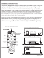
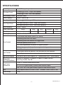
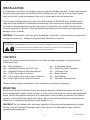
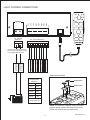
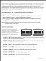
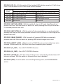
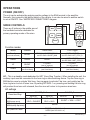
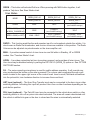
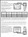
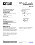
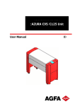
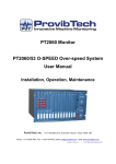
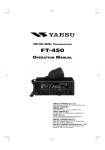
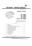
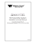
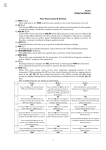
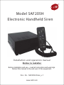
Model SAF205H
Electronic Handheld Siren
Installation and operation manual
Notice to installer
Before installation and use -- read all instructions and warnings.
Deliver this manual to the end user of this equipment.
Doc. No.: SAF205H Siren_v.1
www.cell2.com
Table of Contents
GENERAL DESCRIPTION............................................................................................2
SPECIFICATIONS........................................................................................................3
INSTALLATION............................................................................................................4
CONTENTS.............................................................................................................4
MOUNTING.............................................................................................................4
WIRING...................................................................................................................5
Electrical Connections..........................................................................................5
Light Control Connections...................................................................................7
PROGRAMMING....................................................................................................8
OPTION SWITCHES.............................................................................................10
OPERATION................................................................................................................11
POWER (ON/OFF).................................................................................................11
SIREN CONTROLS................................................................................................11
Hands-Free Button..............................................................................................11
Siren Button.........................................................................................................12
Radio Button........................................................................................................12
Manual Button....................................................................................................12
Horn Button........................................................................................................12
PA.......................................................................................................................12
HRT Input (optional)...........................................................................................12
PKL Input (optional)............................................................................................12
LIGHT CONTROLS.............................................................................................13
LV Buttons..........................................................................................................13
Auxiliary Buttons..................................................................................................13
TROUBLESHOOTING...............................................................................................14
SAF205H Siren_v.1
-1-
GENERAL DESCRIPTION
The SAF205H Handheld Siren Amplifier is a premium 200W unit designed for single or dual 100W
speaker use with full lighting control. A remote handheld controller is connected to the amplifier
with a thin cable. The control head comes with a noise-canceling microphone for PA use and
push-button override in all modes. It contains illuminated buttons that change color to indicate
status. A potentialmeter is also provided on the controller to adjust PA volume. The SAF205H also
includes 3 push buttons for primary lighting system control and 4 auxiliary output push buttons;
each button is capable of 10 amps current. There are 3 primary operation modes: HandsFree,
Siren, and Radio with a Horn button Override and a Manual button Override. The Radio and Siren
volume can be adjusted on the side of the siren amplifier.
A Horn Ring Transfer input is available for the connection to vehicle horn ring or remote switch for
hands-free siren operation. A Park Kill input is available for connection to a door switch, etc. to
stop siren tones when exiting the vehicle. A 16-position DIP switch on the amplifier allows
selection of various options. The handheld controller is backlighted with LED’s for night visibility.
front view Handheld controller
front view (Light control connector)
MIC
SW4 & SW5
LED INDICATOR
HANDSFREE
mode
RADIO
LIGHT CONTROL
AUX SW BUTTONS
SW1
SW2
SW3
SW4
SW5
SIR
VOL
SW5
SW4
SW2
SW3
LV2
SW1
RAD
VOL
POS
POS
SPK+
SPK
SIREN
mode
NEG
SIREN
NEG
HF
VID
HORN
ENA
HORN
PKL
MAN
side view (12-Pin Siren Connector)
RAD
MANUAL
MIC VOL.
ADJUST
LV1
HRT
PA
CONTROLLER
PORT
LIGHT CONTROL
LV BUTTONS
RAD
LV3
LV2
LV3
LV1
POWER IN
+
+
SIREN FUSE
SAF205H
RADIO
mode
side view (DIP switches)
ON
1
DIP
2
3
4
5
6
7
8
ON
1
DIP
2
3
4
5
6
7
8
SAF205H Siren_v.1
-2-
SPECIFICATIONS
Input Voltage
Siren Input Current
10-16VDC (negative ground)
8.5Amps (@13.6VDC - single 100W speaker)
16Amps (@13.6VDC - dual 100W speakers)
Siren Standby Current
Less than 150mA
Audio Frequency
200Hz - 10kHz ± 3db
Siren Output Power
40 watts (@13.6VDC-single 100W speaker)
Siren Output Power
100 Watts RMS MAX. (14VDC - single 100W speaker)
200 Watts RMS MAX. (14VDC - dual 100W speakers)
Siren Frequency
725Hz - 1465Hz
Tones/ Cycle Rates
HORN
WAIL
YELP
PHASER
HILO
Cycle Rates
Composite (Constant)
12CPM
190CPM
650CPM
60CPM
Operating Temp
-25° C to +60° C (-15° F to +140° F)
3 push-button Mode switch (SIREN, HF, RADIO).
Momentary push-button Horn switch.
Momentary push-button Manual/Tone toggle switch.
Siren Controls
ENA input (positive) to turn on unit.
HRT input programmable for positive or negative operation.
PKL input programmable for positive or negative latching operation.
Side DIP switch option selectors.
Light Controls
3 push-button switch with position 3 siren activation and LED indicators.
4 - on/off lighted push-button switches with replaceable legends.
Light Output Ragings
10A fuse on each of the 8 outputs. (LV - 3 push buttons & SW - 4 push buttons)
Siren Connections
(Removable
12-P Terminal Block)
Positive x 2, Negative x 2, Speaker x 2, Radio x 2, Enable, Park Kill,
Horn Ring Transfer, Park Kill.
Power In 2-position screw terminal inputs.
Light Control
Connections
LV1, LV2, LV3 (push buttons) 3-position screw terminal outputs.
SW1, SW2, SW3, SW4 (push buttons) 5-position screw terminal outputs.
Size
Siren Amplifier 20.8cm x 18.8cm x 6.9cm
Boxed Weight
2.5kg
Controller: 5.6cm x 14cm x 3.3cm
SAF205H Siren_v.1
-3-
INSTALLATION
It is essential to install the unit properly to ensure safe and reliable operation. Please read through
all instructions thoroughly and carefully before installing the unit. Failure to follow these instructions could result in serious damage to the unit or vehicle and may void warranties.
The correct mounting and wiring is key to the effectiveness of SAF205H siren. Installers must
read and follow installation instructions and warnings in the manual from original manufacturer.
The vehicle operator should verify the siren system is fastened to the vehicle securely and is
functioning properly. Failure to follow all safety precautions and instructions may cause property
damage, injury, or death.
WARNING: The installer must have good knowledge of electricity, vehicle electrical systems and
emergency equipment. Always seek professional assistance if in doubt.
WARNING
Sound Hazard - Sound level from siren speaker (>120dBA @ 10 feet) may cause hearing damage.
Do not operate siren without adequate hearing protection for you and anyone in immediate vicinity.
(Ref. OSHA 1910.95 for occupational noise exposure guidelines)
CONTENTS
Inspect the product contents carefully to see if there is shipping damage or missing content.
Contents include:
1pc – Siren (Amplifier)
1pc – Handheld Controller with Coil Cord
1pc – Handheld Controller Mounting Bracket
1pc – 12-Pin Siren Input Connector
1pc – 2-Pin Light Control Power Input Connector
1pc – 8-Pin Light Control Output Connector
1pc – 6’ Extension Cable
1pc – Extension Cable Connector
1pc – 15 Button Plate
1pc – Button Decals
1pc – User Manual
1pc – Operation Warning Label
Please contact supplier immediately if any component is missing or damaged.
MOUNTING
Mount the siren unit in a location that is not exposed directly to weather elements such as the
driver compartment firewall, below the seat, or in the trunk; and away from any air bag deployment
areas. Mount the handheld controller in an area where it can be easily accessed by the vehicle
operator, and not affect the vehicle the air bag. Be sure that all wiring harness connections are
made prior to connecting the harness to the amplifier unit.
WARNING: Do not interfere with the proper operation of the vehicle airbag deployment system.
Ensure to install “Operation Warning Label” in the vehicle in an area that is clearly visible to
operators and passengers.
SAF205H Siren_v.1
-4-
WIRING
Use wires that are capable of handling the required current. Route the wires properly to prevent
wear, overheating and interference with air bag deployment. Ensure that all connections are tight
and double check wiring before connecting to the vehicle battery.
ELECTRICAL CONNECTIONS
Electrical connections to the unit are made by using block plugs and screw terminals. Route
all wiring to the siren and secure onto block plug terminals, then plug onto the siren. The
plug can be easily removed without unwiring when the unit requires servicing. The power
supply for the fused amplifier (12-P plug) must be capable of delivering peak currents up to
50A for adequate short circuit protection and proper operation. It is recommended to wire
directly to the vehicle battery.
WARNING: ensure that all wires are firmly secured onto the block plug, and plug is firmly
secured onto the siren.
Wire Size and Termination – The “AMPLIFIER CONNECTIONS” diagram shows the
minimum size of the wires used for each connection, along with recommended lead color.
If the wire is longer than 10 ft., use the next larger size.
ENA Input Connection – This serves as the power switch for the entire unit. Connect to a
positive circuit controlled by the vehicle ignition switch, usually a terminal at the vehicle
fuse panel. It is not recommended to make permanent power connection as this may drain
battery.
HRT Input Connection – The Horn Ring Transfer input allows activation by an external
source of either the Horn or other function. It can be set for positive or negative switching,
see DIP-SW1-1 (HRT_N) under OPTION SWITCHES section.
PKL Input Connection – The Park Kill input may be connected to the vehicle door switch
or other switching device to turn off any siren tone when activated. It can be set for
positive or negative switching, see DIP-SW1-2 (PKL_N) under OPTION SWITCHES
section.
RAD Input Connection – Connect to radio output terminals or its speaker. The Radio
volume can be adjusted by using a small flat blade screwdriver.
Speaker Output Connection – Both connections must be used. Two speakers may be
connected in parallel.
VID Output Connection (Option) – A Video Camera trigger output is activated when ever
the unit is in SIREN or HF mode. (Not available in this model).
SAF205H Siren_v.1
-5-
SIR
VOL
RAD
VOL
POS
POS
NEG
SPK+
NEG
SPK
VID
ENA
PKL
HRT
RAD
RAD
AMPLIFIER CONNECTIONS
SIREN FUSE
SAF205H
12-P Terminal Block Plug
20A Automotive
Type Fuse
Plug installed
this orientation
#14 AWG RED x2
Use second lead
for dual speaker
#14 AWG BLK x2
Use second lead
for dual speaker
dual speaker connect + to +
#18 AWG BRN x2
(#16 AWG dual speaker)
ENA
The leads and
recommended
colors shown
are user-supplied.
#22 AWG ORG
Unit Enable (like an ON/OFF switch)
Connect to positive circuit (fuse panel)
controlled by ignition or other switch
VID
#22 AWG BLU Connect to camera input
ADDED
DOOR SWITCH
PKL
+VDC
DOME
LIGHT
#22 AWG WHITE
PKILL
PKILL
+VDC Switching
example
Recommended
Wire Size
Amps
Size
5-10
#16
10-15
#14
15-25
#12
25-40
#10
40-60
#8
MOMENTARY
FOOT SWITCH
-VDC Switching
example
Must set PKL_N
option switch
HRT
+VDC
+VDC
HRT
#22 AWG YELLOW
-VDC Switching
example
Must set HRT_N
option switch
HRT
HRT
+VDC Switching example
RAD
Use next larger size
if longer than 10ft.
#22 AWG GRAY x2 Connect to output
jack, terminals, or speaker of radio
SAF205H Siren_v.1
-6-
LIGHT CONTROL CONNECTIONS
SW5
SW4
SW2
SW3
SW1
LV3
LV1
2-P Terminal
Block Plug
LV2
POWER IN
+
+
8-P Terminal Block Plug
Load SW5 10 Amps Max.
Load SW4 10 Amps Max.
Load SW3 10 Amps Max.
Load SW2 10 Amps Max.
Load LV3 10 Amps Max.
Load SW1 10 Amps Max.
Load LV2 10 Amps Max.
Load LV1 10 Amps Max.
Circuit Breaker
Limit input up to
40 Amps Max.
Circuit Breaker
Limit input up to
40 Amps Max.
Internal screw pressure terminal
will accept up to #6 AWG for input
current higher than 40 Amps
Hand held controller
1
Recommended
Wire Size
Amps
Size
5-10
#16
10-15
#14
15-25
#12
25-40
#10
40-60
#8
Button Decal
MAN
Button Plate
Use next larger size
if longer than 10ft.
NOTE: The controller is shipped without any button
plates or decals installed. Place decal onto button
plates, then install plates onto each button.
SAF205H Siren_v.1
-7-
LIGHT CONTROL CONNECTIONS
Power – The power input for the light controls (the three LV switches and the four auxiliary
control switches) are separate from the power inputs for siren. This design helps prevent a
fault in one main circuit from affecting another main circuit.
Fuses/Breakers – Each light control output is fused and should be limited to 10 Amps.
Proper rated circuit breakers should be connected between the power source and light
control power inputs. Refer to “FUSE LOCATION” diagram for proper fuse location below.
WARNING: Improper circuit breakers or fuses can result in damage to the unit and/or vehicle.
(open siren top view)
-10-
-10-
-10-
-10-
-10-
-10-
-10-
SW3
SW2
SW1
LV3
LV2
LV1
-10-
SW5
10A FUSE
SW4
-10-
FUSE LOCATION
PROGRAMMING
Once the electrical connections are made and the power is available to the unit, each of the three
LV buttons and four auxiliary control buttons are ready to be programmed. The programming
mode is entered by changing the DIP switch.
Follow these steps to program the unit:
Get into program mode.
1. Turn unit on with enable input.
2. Enter the program mode by turning DIP-SW2-8 (PRG) switch on.
Set Auxiliary Control Buttons Operation (all LV buttons off)
1. With all LV buttons off, each auxiliary switch current operation program status is indicated
on each push button. See the table below for switch status definition.
2. Change button operation by momentarily pushing the auxiliary button.
LED showing
Red Steady
Red Flashing
Red off
AUXILIARY button setting
PUSH on / PUSH off (default)
MOMENTARY
TIMED MOMENTARY (10 seconds)
NOTE: The Timed Momentary operation, typically used as a Gun Lock Timer, must begin
with push button 3. If push button 3 is programmed as timed momentary, only
then push button 2 may be programmed also as a timed momentary and so on.
SAF205H Siren_v.1
-8-
Each LV button (LV1, LV2, LV3) may be programmed to automatically turn on any of the auxiliary
button controls (SW1~SW3) except Timed Momentary. These auxiliary button controls may still
be operated manually even if they were turned on automatically. Each time the LV button
changes position, the combined auxiliary button controls are turned on or off. When the LV button
is turned off, the entire auxiliary button controls tied to a position on the LV button is turned off
while the other auxiliary buttons are unaffected.
Set LV buttons (LV1, LV2, LV3) and Auxiliary buttons Combination
1. Activate desired LV button to program.
2. Press the desired auxiliary button to change LED color to Red. Press the auxiliary button
again to change LED color to Green to remove from combination.
3. Once the LV buttons are programmed as desired, save and exit programming mode by
turning DIP-SW2-8 (PRG) switch off.
NOTE: If the unit is turned off before the DIP-SW2-8 (PRG) switch is turned off, the new
programming will not be saved.
OPTION SWITCHES
Various options can be selected by
turning on or off DIP switches located
on the side of the siren. The DIP
SWITCH functions are described below.
(see Appendix 1 for quick reference)
DIP-SW1
DIP-SW2
ON
1
DIP
2
3
4
5
6
7
8
ON
1
DIP
2
3
4
5
6
7
8
DIP-SW1-1 (HRT_N) HRT Input Polarity – The HRT input is normally activated by a positive
voltage. Set switch on to activate with negative.
DIP-SW1-2 (PKL_N) PKL Input Polarity – The PKL input is normally activated by a positive
voltage. Set switch on to activate with negative.
DIP-SW1-3 (HILO) – HiLo tone replaces Phaser tone by setting this switch on.
DIP-SW1-4 (PHASER_D) – Phaser/HiLo tones are disabled by setting this switch on.
DIP-SW1-5 (HORN_D) – Horn tone is disabled by setting this switch on.hart.
DIP-SW1-6 (SIREN_SW1) – See “Siren Mode settings” chart.
DIP-SW1-7 (SIREN_SW2) – See “Siren Mode settings” chart
SAF205H Siren_v.1
-9-
DIP-SW1-8 (TA_D) – With this switch off, the handheld LED indicator operates in Traffic Arrow
mode. With this switch on, the Traffic Arrow mode is disabled.
Press SW4
button:
Handheld controller LED Indicator
With DIP-SW1-8 off (Traffic Arrow mode)
With DIP-SW1-8 on (Regular mode)
1st Press
LED flashes right to left
Left LED on
2nd Press
LED flashes left to right
Right LED on
3rd Press
4th Press
LED flashes center out
Left and Right LEDs on
all LEDs off
all LEDs off
DIP-SW2-1 (HRT_HF_HORN) – With this switch off, when in HF mode, Horn Ring will not
produce Horn tone. With this switch on, when in HF mode, pressing Horn Ring for more than
0.5 seconds produces Horn tone.
DIP-SW2-2 (HRT_STBY_D) – With this switch off, when in standby (ie. no modes selected),
pressing Horn Ring or RAD button produces Horn tone. With this switch on, Horn Ring will not
produce Horn tone.
DIP-SW2-3 (MAN_CHANGE) – With this switch off, pressing MAN button momentarily
produces next tone. With this switch on, pressing MAN button changes to next tone.
DIP-SW2-4 (SHORT _MAN) – With this switch off, MAN Siren tone slowly winds down when
released. With this switch on, MAN Siren tone stops immediately when released.
DIP-SW2-5 (LV_SW1) – See LIGHT CONTROLS section.
DIP-SW2-6 (LV_SW2) – See LIGHT CONTROLS section.
DIP-SW2-7 (AUTSR_D) – With this switch off, Siren tone is automatically activated when LV3
button is activated. With this switch on, Automatic Siren tone is disabled.
DIP-SW2-8 (PRG) –Turn this switch on to enter Programming mode; see PROGRAMMING
section.
SAF205H Siren_v.1
- 10 -
OPERATIONS
POWER (ON/OFF)
The unit can be activated by applying positive voltage to the ENA terminal in the amplifier.
Normally, this is wired to the ignition switch of the vehicle; it can also be wired to another switch
to act as ON/OFF. See “AMPLIFIER CONNECTIONS” diagram.
SIREN CONTROLS
LV3
LV2
There are 5 buttons in the middle area of
the handheld controller dedicated for
primary operating modes of the siren.
MAN
HF
HORN
LV1
SIREN
MAN
HORN
HF
SIREN
RADIO
RADIO
SW1
SW2
SW3
SW4
SW5
Function modes
Modes
Standard
Standby
+ MAN button
+ HRT trigger
MANUAL / SHORT MANUAL
HORN / SILENT
see DIP-SW2-4 SHORT_MAN
see DIP-SW2-2 HRT_STBY_D
(no mode selected)
SILENT
RADIO
RADIO
RADIO
HF
SILENT
CYCLER
HORN / RADIO
see DIP-SW2-2 HRT_STBY_D
CYCLER
(see HF settings)
(see HF settings)
WAIL
YELP
YELP
(see Siren Mode)
(see Siren Mode)
(see Siren Modes)
SIREN
HF – This is a standby mode dedicated for HRT (Horn Ring Transfer). When installing the unit, the
auxiliary input must be connected to the horn ring or other switching device. Tap the horn ring or
MAN button once to activate Wail tone, then tap again to activate Yelp tone, and quickly tap the
horn ring twice to shut off siren tone. By setting DIP-SW2-1 on, pressing and holding the horn ring
will produce Horn tone until released, then the siren will return to its previous siren tone.
HF settings
PHASER_D off
Press Horn Ring:
HRT tap once
(MAN press once)
HILO on
SILENT-> WAIL->
YELP-> PHASER
SILENT-> WAIL->
YELP-> HILO
HRT quickly tap twice
(MAN quickly tap twice)
HRT press +0.5 secs
PHASER_D on
HILO off
HILO off
HILO on
SILENT -> WAIL -> YELP
SILENT
SILENT (with DIP-SW2-1 off)
HORN (with DIP-SW2-1 on)
SAF205H Siren_v.1
- 11 -
SIREN – This button will activate Wail tone. When pressing with MAN button together, it will
produce Yelp tone. See Siren Modes chart.
Siren Modes
SIREN_SW1 off
SIREN_SW1 off
SIREN_SW1 on
SIREN_SW2 off
SIREN_SW2 on
SIREN_SW2 ---
SIREN
WAIL
YELP
(see PHASER settings)
SIREN + MAN (or HRT)
(w/ MAN_ CHANGE off)
YELP
(see PHASER settings)
SIREN + MAN (or HRT)
WAIL / YELP
YELP / PHASER
PHASER / YELP
(see PHASER settings)
(see PHASER settings)
MODE
PHASER
PHASER
YELP
RADIO – This function amplifies the radio speaker input for re-broadcast outside the vehicle. It is
also known as Radio Re-broadcaster, and no siren tones are available in this position. The Radio
Volume can be adjusted via potentiometer on the siren amplifier unit.
MAN – It provides manual control of siren tone rise and fall while in Standby, HF or SIREN
modes. See “Function Modes” chart.
HORN – It provides a simulated air-horn tone when pressed, and overrides all siren tones. The
Horn tone may be disabled entirely by setting the DIP-SW1-5 (HORN_D) option on. See OPTION
SWITCHES section.
PA – The noise-canceling microphone is used for public address operation. It will override any
siren mode when the button on the side is pressed. The volume can be adjusted through a pot
switch located in the upper right corner of the control head. Insert a small, flat-blade screwdriver
into the pot switch; turn clockwise direction to increase the sound level.
HRT Input (optional) – The Horn Ring Transfer input may be connected to the horn ring or other
switching devices. Activating this input will produce Horn tone or other functions depending on the
push button position.
PKL Input (optional) – The Park Kill input may be connected to the vehicle door switch or other
switching device to turn off any siren tone when activated. The siren will remain deactivated until
the vehicle is shifted into gear or the door is closed and the siren is automatically restarted.
SAF205H Siren_v.1
- 12 -
LIGHT CONTROLS
The 3 LV buttons (LV1, LV2, LV3) in the top
area of the handheld controller are dedicated
for primary lighting functions. There are
additional 4 programmable on/off buttons for
auxiliary lighting or other devices.
LV3
LV2
LV1
LV3
LV2
MAN
HORN
HF
SIREN
LV1
LV buttons – The LV buttons can be set
to operate as a Progressive or Nonprogressive switching. There are four
modes available.
RADIO
SW1
SW2
SW3
SW4
SW5
LV Button Modes
LV Button Modes:
MODE1
LV_SW1 off
LV_SW2 off
MODE2
LV_SW1 off
LV_SW2 on
MODE3
LV_SW1 on
LV_SW2 off
MODE4
LV_SW1 on
LV_SW2 on
LV1
LV1
LV1
LV1、LV3
LV1
LV2
LV2
LV2
LV2、LV3
LV1、LV2
LV3
LV1、LV2、LV3
LV3
LV1、LV2、LV3
LV1、LV2、LV3
Progressive/Non-progressive Switch - There are 4 different combination modes available. This is
configured by setting the DIP-SW 2-5 (LV_SW1) and DIP-SW 2-6 (LV_SW2) option. At each of
the LV switches, it is possible to program the additional AUX on/off buttons to be activated
together.
LV3 Button – When LV3 is switched on, the siren tone is automatically activated. This function
can be disabled by setting the DIP-SW2-7 (AUTSR_D) option; see OPTION SWITCHES section.
VID Output Option – The VID output is activated whenever the unit is in SIREN or HF modes.
(Available in future models).
AUXILIARY Buttons – The 4 lighted on/off
buttons are for controlling other lighting
functions or devices. SW1~SW3 buttons can
be programmed for three operating modes
such as Push On/Off, Momentary, or Timed
momentary; see PROGRAMMING section.
SW4 button is designed to control SW4 and
SW5 outputs, which is mainly used to control
the traffic arrow functions.
SW1
LV3
SW2
LV2
LV1
SW3
SW4
SW5
MAN
HORN
HF
SIREN
RADIO
- 13 -
SW1
SW2
SW3
SW4
SW5
1st Press
Activates output SW4
2nd Press
Activates output SW5
3rd Press
Activates outputs SW4 & SW5
4th Press
Deactivates outputs SW4 & SW5
See DIP-SW1-8 (TA_D) for corresponding Handheld controller LED indicator.
TROUBLESHOOTING
SAF205H Siren has been designed to provide reliable quality service under the worst conditions.
If encounter any difficulties, check its installation or speakers. The following table represents
problems and probable causes.
PROBLEM
POSSIBLE CAUSE
NO SOUND
Loose wires or connectors
Bad speaker or speaker wiring
Siren fuse down
PA volume in the lowest sound level
NO SIREN
High input voltage (greater than 16V)
PKL activated
PA button pressed
Speaker not connected
Defective speaker
TONE-PA WORKS
DISTORTED
SIREN SOUND
Bad speaker
Damaged or loose speaker housing or tip
Low voltage to siren amplifier
Loose wires or connectors at ENA or SPKR
SIREN VOLUME LOW
Speaker connected to wrong tap
Low voltage to siren amplifier
High resistance in speaker wiring
PA volume in low position
WEAK PA
Microphone no held close to mouth
Defective microphone
Microphone loose connection
INTERMITTENT
High input voltage (greater than 16V)
Bad speaker driver
Unused wires touching vehicle ground or supply
SAF205H Siren_v.1
- 14 -
Appendix 1
DIP-SW1 Options
FUNCTIONS
PORT
DIP-SW1
OFF
ON
1-1
HRT_N
HRT activate with positive
HRT activate with negative
1-2
PKL_N
PKL activate with positive
PKL activate with negative
1-3
HILO
PHASER normal operation
PHASER replaced by HILO
1-4
PHASER_D
PHASER and HILO normal operation
PHASER and HILO disabled
1-5
HORN_D
HORN normal operation
HORN disabled
(replaced by PHASER/HILO/YELP)
1-6
SIREN_SW1
1-7
SIREN_SW2
1-8
TA_D
for configuration of Siren tone (see "Siren Modes" chart)
LED Indicator as Traffic Arrow
LED Indicator Constant
DIP-SW2 Options
PORT
DIP-SW2
2-1
HRT_HF_HORN
FUNCTIONS
OFF
ON
During HF, HORN is disabled for HRT
During Standby, HRT and RADIO
produces HORN tone.
During SIREN, press MAN produces
next tone when pressed
MAN Siren tone slowly winds down
when released
During HF, press HRT for more than
0.5 secs produces Horn tone
During Standby and RADIO,
HRT is disabled
During SIREN, press MAN skips to
next tone when pressed
MAN Siren tone stops immediately
when released
2-2
HRT_STBY_D
2-3
MAN_CHANGE
2-4
SHORT_MAN
2-5
LV_SW1
2-6
LV_SW2
2-7
AUTSR_D
Automatic Siren at LV3
Automatic Siren Disabled at LV3
2-8
PRG
Operation Mode
Light Control Program Mode
for configuration of Progressive or Non-Progressive switching
(see "LV Button Modes" chart)
SAF205H Siren_v.1
- 15 -